Sony SAVA-700 Service Manual
Hide thumbs
Also See for SAVA-700:
- Operating instructions manual (20 pages) ,
- Operating instructions manual (20 pages) ,
- Operating instructions manual (20 pages)
Table of Contents
Advertisement
Advertisement
Table of Contents

Related Manuals for Sony SAVA-700


Summary of Contents for Sony SAVA-700
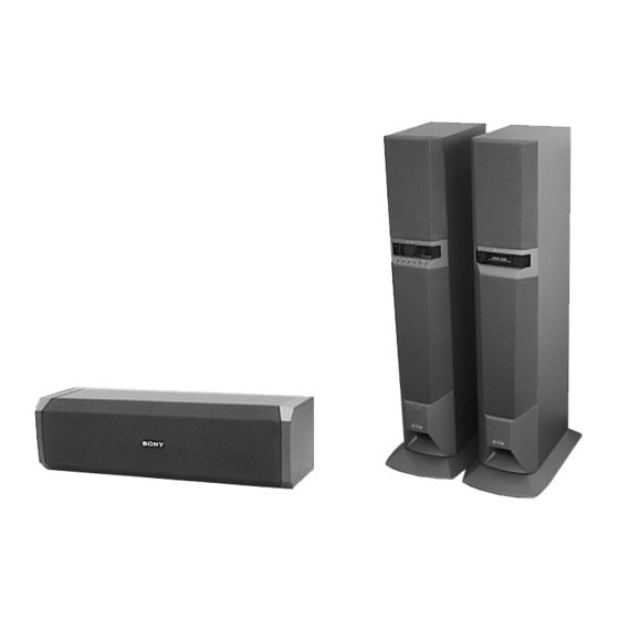
- Page 1 US Model AEP Model UK Model E Model (L-ch) (R-ch) Photo: SS-T100 Photo: Main Unit The SAVA-700 composed of the following table. Front Speaker Main Unit Center/Rear Speaker SS-T100 SPECIFICATIONS – Continued on next page – HOME THEATER ACTIVE SPEAKER SYSTEM...
-
Page 2: Table Of Contents
LINE WITH MARK ! ON THE SCHEMATIC DIAGRAMS AND IN THE PARTS LIST ARE CRITICAL TO SAFE OPERATION. REPLACE THESE COMPONENTS WITH SONY PARTS WHOSE PART NUMBERS APPEAR AS SHOWN IN THIS MANUAL OR IN SUPPLEMENTS PUB- LISHED BY SONY. -
Page 3: Servicing Notes
SECTION 1 SERVICING NOTES MODEL IDENTIFICATION SAFETY CHECK-OUT After correcting the original service problem, perform the follow- – Rear view – ing safety check before releasing the set to the customer: Check the antenna terminals, metal trim, “metallized” knobs, screws, and all other exposed metal parts for AC leakage. Check leakage as described below. -
Page 4: General
SECTION 2 GENERAL • LOCATION OF CONTROLS Main Unit (L-ch) – Front View – INPUT button SURROUND button CENTER MODE button S. WOOFER button MASTER VOL +/– buttons STANDBY, ON, READY indicators U button – Rear View – TV IN jack VIDEO IN jack AUX IN jack 5.1CH INPUT (FRONT, REAR, WOOFER, CENTER) jack... -
Page 5: Disassembly
SECTION 3 DISASSEMBLY Note: Follow the disassembly procedure in the numerical order given. AMPLIFIER SECTION 2 grille frame (A) 5 washer ass’y L-ch speaker section 3 screw (BVTT4 × 25) 4 washer (BF) 7 flat wire (CN503) 8 connector (CN907) 6 screw (BVTT4 ×... - Page 6 SERVICE POSITION 1 Remove the amplifier section. (Refer to page 5) 2 two screws (transistor) 5 heatsink and AMP board 9 cord bushing 7 bracket 3 two screws (BVTP3 × 8) 6 two screws (BVTP3 × 8) !¡ eleven screws (BVTP3 ×...
- Page 7 !¶ Attach the bracket to the heatsink with two screws. bracket heatsink !• Insert two connectors (CN601, 603) into the connectors MAIN board (CN301, 911) on the MAIN board. !ª Connect the fan motor lead wire to MAIN board connector (CN301). chassis !§...
-
Page 8: Test Mode
[S.WOOFER] [MASTER VOL +] 1. While pressing the both buttons, turn the power ON. 2. Fluorescent indicator tube display “SAVA-700”, after the all lights up, and enter the input check mode. [INPUT] 3. Pressing the button varies the display as follows. SAVA-700 ********* S.WOOFER... - Page 9 4-3. AMP CHECK MODE Procedure: [ ] 1. Push back button to turn the power OFF. 2. Connect the lead wire to TP1 and TP2 on the KEY board. [ ] 3. Push button to power ON. 4. Let the lead wire connected TP1 and TP2. 5.
- Page 10 2. The operation with remote commander is disabled. Demonstration mode sequence: @@@@@@@@@ @ H E L L O @ WELCOME TO SAVA SOUND SYSTEM I AM SAVA-700 MY FEATURES ARE 4 INPUTS AND 5 SURROUND MODE LISTEN TO MY SOUND 5.1 INPUT...
-
Page 11: Diagrams
SECTION 5 DIAGRAMS 5-1. NOTE FOR PRINTED WIRING BOARDS AND SCHEMATIC DIAGRAMS • Circuit Boards Location Note on Printed Wiring Board: Note on Schematic Diagram: • X : parts extracted from the component side. • All capacitors are in µF unless otherwise noted. pF: µµF •... -
Page 12: Printed Wiring Board - Main Board
SAVA-700/SS-T100 5-2. PRINTED WIRING BOARD – MAIN Board – • See page 11 for Circuit Boards Location. (Page 20) (Page 18) (Page 18) (Page 16) (Page 16) (Page 16) (Page 16) (Page 16) (Page 16) (Page 18) (Page 16) - Page 13 SAVA-700/SS-T100 5-3. SCHEMATIC DIAGRAM – MAIN Board (1/3) – • See page 22 for Waveform. • See page 22 for IC Block Diagrams. • Semiconductor Location Ref. No. Location D101 D-13 D102 D-13 D312 D353 D401 E-12 D701 D703 D704...
-
Page 14: Schematic Diagram - Main Board (2/3)
SAVA-700/SS-T100 5-4. SCHEMATIC DIAGRAM – MAIN Board (2/3) – • See page 22 for IC Block Diagrams. (Page 21) (Page 17) (Page 13) (Page 17) (Page 19) (Page 15) -
Page 15: Schematic Diagram - Main Board (1/3)
SAVA-700/SS-T100 5-5. SCHEMATIC DIAGRAM – MAIN Board (3/3) – • See page 23 for IC Block Diagrams. (Page 13) (Page 14) (Page 19) (Page 19) (Page 17) (Page 17) (Page 17) The components identified by mark ! or dotted line with mark ! are critical for safety. -
Page 16: Printed Wiring Boards - Filter/Thermo/Reg/T2/T1/Standby/Ac-Sw Board
SAVA-700/SS-T100 5-6. PRINTED WIRING BOARDS – FILTER/THERMO/REG/T2/T1/STANDBY/AC-SW Board – • See page 11 for Circuit Boards Location. • Semiconductor (Page 12) Location – FILTER Board – Ref. No. Location D351 D352 (Page 12) IC301 IC302 (Page 12) IC303 IC304 Q303... -
Page 17: Schematic Diagram - Filter/Thermo/Reg/T2/T1/Standby/Ac-Sw Board
SAVA-700/SS-T100 5-7. SCHEMATIC DIAGRAM – FILTER/THERMO/REG/T2/T1/STANDBY/AC-SW Board – (Page 14) (Page 15) (Page 13) (Page 15) (Page 15) (Page 14) The components identified by mark ! or dotted line with mark ! are critical for safety. Replace only with part number specified. -
Page 18: Printed Wiring Board - Amp Board
SAVA-700/SS-T100 5-8. PRINTED WIRING BOARD – AMP Board – • See page 11 for Circuit Boards Location. (Page 12) (Page 12) (Page 12) • Semiconductor Location Ref. No. Location Ref. No. Location D601 Q601 D602 Q602 D603 Q603 D771 Q604... -
Page 19: Schematic Diagram - Amp Board
SAVA-700/SS-T100 5-9. SCHEMATIC DIAGRAM – AMP Board – • See page 23 for IC Block Diagrams. (Page 15) (Page 15) (Page 14) The components identified by mark ! or dotted line with mark ! are critical for safety. Replace only with part number specified. -
Page 20: Printed Wiring Boards - Display/Led/Key Board
SAVA-700/SS-T100 5-10. PRINTED WIRING BOARDS – DISPLAY/LED/KEY Board – • See page 11 for Circuit Boards Location. (Page 12) • Semiconductor Location –DISPLAY Board – Ref. No. Location D501 D502 D503 D507 IC501 IC502 IC503 Q501 Q502 Q503 Q504 Q505... -
Page 21: Schematic Diagram - Display/Led/Key Board
SAVA-700/SS-T100 5-11. SCHEMATIC DIAGRAM – DISPLAY/LED/KEY Board – • See page 22 for Waveform. (Page 14) - Page 22 • Waveforms • IC Block Diagrams – MAIN Board – – DISPLAY Board – – MAIN Board – IC201 – 203 LC75373ED 1 IC400 #¢ (OSC) 1 IC501 #∞ (X2) – LFIN – 5.5 Vp-p 3.6 Vp-p – – LFOUT –...
- Page 23 IC401 CXA8079S 47 46 45 44 43 42 41 30 29 28 C-TRIM R-B.P.F. L+R-RECT VCS-LOG N-GEN N-BPF BAL-DET L-R-RECT DUAL-TIME CMODE SMUTE BALCONT N-OH R-RECT COMB-NET VCRX8 VLR-LOG L-B.P.F. L-RECT VREF – AMP Board – IC701 µPC1237HA IC606 STK350-230 OVER LOAD DET INPUT MUTE...
-
Page 24: Ic Pin Function Description
5-12. IC PIN FUNCTION DESCRIPTION • DISPLAY BOARD IC501 µPD78043FGF-059-3B9 (SYSTEM CONTROLLER) Pin No. Pin Name Description 1 to 7 7G to 1G Gird drive signal output to the fluorescent indicator tube (FL501) — Power supply terminal (+5V) POWER RY Relay drive signal output for the power on/off control “H”: relay on (power on) Serial chip enable signal output to the dolby surround pro-logic circuit (IC400, 401) SUR CE... - Page 25 Pin No. Pin Name Description 42, 43 — Not used (pull down) Sircs remote control signal input from the remote control receiver (IC503) and CONTROL S TV SIRCS IN (CONTROL S TV IN: used for the US model only) 45, 46 —...
-
Page 26: Exploded Views
SECTION 6 EXPLODED VIEWS NOTE: • -XX and -X mean standardized parts, so they • Items marked “*” are not stocked since they The components identified by mark ! or dotted line with mark may have some difference from the original are seldom required for routine service. - Page 27 (2) AMPLIFIER SECTION supplied with supplied Q603, 604 supplied supplied supplied T900 M371 supplied supplied supplied AEP, E supplied supplied supplied The components identified by mark ! or dotted line with mark ! are critical for safety. Replace only with part number specified. Ref.
- Page 28 (3) R-CH SPEAKER SECTION supplied SP302 SP303 SP301 supplied SP401 supplied supplied Ref. No. Part No. Description Remark Ref. No. Part No. Description Remark 4-217-244-01 PANEL (R), DUCT 4-967-287-01 CUSHION (A) X-4951-172-1 FRAME (B) ASSY, GRILLE 4-218-224-01 PACKING (B) X-4951-171-1 FRAME (A) ASSY, GRILLE 4-218-223-01 PACKING (A) 4-914-430-11 SCREW (4X20), TAPPING 4-874-614-61 SCREW +BVTP 3.5X16...
- Page 29 (4) CENTER AND REAR SPEAKER SECTION (SS-T100) supplied SP502 SP503 SP501 supplied Ref. No. Part No. Description Remark Ref. No. Part No. Description Remark X-4951-263-1 FRAME ASSY, GRILLE * 156 4-963-075-01 CATCHER 4-874-614-61 SCREW +BVTP 3.5X16 SP501 1-504-510-21 SPEAKER (2.5cm) 4-219-076-01 COVER SP502 1-529-304-11 SPEAKER (8cm)
-
Page 30: Electrical Parts List
SECTION 7 AC-SW ELECTRICAL PARTS LIST NOTE: • Due to standardization, replacements in the • Items marked “*” are not stocked since they The components identified by mark ! or dotted line with mark are seldom required for routine service. parts list may be different from the parts speci- ! are critical for safety. - Page 31 DISPLAY Ref. No. Part No. Description Remark Ref. No. Part No. Description Remark IC606 8-749-011-16 IC STK350-230 R646 1-249-417-11 CARBON 1/4W R647 1-249-421-11 CARBON 2.2K 1/4W <IC/TRANSISTOR> ! R648 1-249-393-11 CARBON 1/4W F ! R649 1-249-393-11 CARBON 1/4W F Q601 8-729-119-76 TRANSISTOR 2SA1115TP-EF ! R772 1-249-413-11 CARBON...
- Page 32 DISPLAY FILTER Ref. No. Part No. Description Remark Ref. No. Part No. Description Remark < IC > R556 1-249-429-11 CARBON 1/4W R560 1-249-415-11 CARBON 1/4W IC501 8-759-580-05 IC uPD78043FGF-059-3B9 R561 1-249-415-11 CARBON 1/4W IC502 8-759-165-81 IC PST600D-T R562 1-249-417-11 CARBON 1/4W IC503 8-759-459-86 IC NJL64H400A...
- Page 33 FILTER MAIN Ref. No. Part No. Description Remark Ref. No. Part No. Description Remark < TRANSISTOR > R529 1-249-421-11 CARBON 2.2K 1/4W R557 1-247-843-11 CARBON 3.3K 1/4W Q303 8-729-141-30 TRANSISTOR 2SC3623ATP-LK Q304 8-729-141-30 TRANSISTOR 2SC3623ATP-LK < SWITCH > Q305 8-729-141-30 TRANSISTOR 2SC3623ATP-LK Q306 8-729-119-79 TRANSISTOR 2SC2785TP-FEK S501...
- Page 34 MAIN Ref. No. Part No. Description Remark Ref. No. Part No. Description Remark C211 1-136-161-00 FILM 0.047uF C212 1-136-161-00 FILM 0.047uF C413 1-126-959-11 ELECT 0.47uF C213 1-126-960-11 ELECT C414 1-126-964-11 ELECT 10uF C415 1-137-367-11 FILM 0.0033uF 5% C214 1-137-367-11 FILM 0.0033uF 5% C416 1-136-177-00 FILM...
- Page 35 MAIN Ref. No. Part No. Description Remark Ref. No. Part No. Description Remark C751 1-126-949-11 ELECT 220uF D801 8-719-933-59 DIODE HZS9C1LTD C752 1-126-968-11 ELECT 100uF D802 8-719-991-33 DIODE 1SS133T-77 C753 1-104-665-11 ELECT 100uF D803 8-719-991-33 DIODE 1SS133T-77 C801 1-104-664-11 ELECT 47uF D804 8-719-991-33 DIODE 1SS133T-77...
- Page 36 MAIN Ref. No. Part No. Description Remark Ref. No. Part No. Description Remark Q701 8-729-900-63 TRANSISTOR BN1F4M-TP R304 1-249-417-11 CARBON 1/4W Q747 8-729-119-79 TRANSISTOR 2SC2785TP-FEK R305 1-249-429-11 CARBON 1/4W Q748 8-729-030-19 TRANSISTOR 2SB1640 (TP) R306 1-249-441-11 CARBON 100K 1/4W Q801 8-729-111-29 TRANSISTOR 2SD1616-TP-K R351 1-249-437-11 CARBON...
- Page 37 MAIN STANDBY Ref. No. Part No. Description Remark Ref. No. Part No. Description Remark ! R759 1-249-474-11 CARBON 1/2W F D951 8-719-200-82 DIODE 11ES2-NTA1B ! R760 1-249-389-11 CARBON 1/4W F D952 8-719-200-82 DIODE 11ES2-NTA1B ! R761 1-249-389-11 CARBON 1/4W F D953 8-719-200-82 DIODE 11ES2-NTA1B ! R762...
- Page 38 SAVA-700/SS-T100 THERMO Ref. No. Part No. Description Remark Ref. No. Part No. Description Remark 4-219-989-01 BRACKET, HOOK (for SS-T100) 1-673-495-11 THERMO BOARD 4-874-614-61 SCREW +BVTP 3.5X16 4-974-805-01 CUSHION (for SS-T100) ************** 4-981-643-01 COVER, BATTERY (for RM-J70) < CAPACITOR > C731 1-164-159-21 CERAMIC 0.1uF...