Sony SAVA-500 Service Manual
Hide thumbs
Also See for SAVA-500:
- Operating instructions manual (20 pages) ,
- Operating instructions manual (20 pages) ,
- Operating instructions manual (20 pages)
Table of Contents
Advertisement
www.freeservicemanuals.info
SAVA-500/SS-CN16/SR16
SERVICE MANUAL
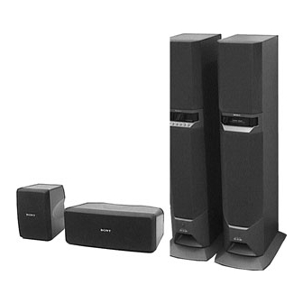
The SAVA-500 composed of the following table.
Front Speaker
Center Speaker
Rear Speaker
MICROFILM
Photo: SS-SR16
Photo: SS-CN16
Main Unit
SS-CN16
SS-SR16
HOME THEATER ACTIVE SPEAKER SYSTEM
05/28/2012
(L-ch)
(R-ch)
Photo: Main Unit
SPECIFICATIONS
World of Free Manuals
US Model
Canadian Model
AEP Model
UK Model
E Model
– Continued on next page –
Advertisement
Table of Contents

Related Manuals for Sony SAVA-500


Summary of Contents for Sony SAVA-500
- Page 1 Canadian Model AEP Model UK Model E Model (L-ch) (R-ch) Photo: SS-SR16 Photo: SS-CN16 Photo: Main Unit The SAVA-500 composed of the following table. Front Speaker Main Unit Center Speaker SS-CN16 Rear Speaker SS-SR16 SPECIFICATIONS – Continued on next page –...
-
Page 2: Table Of Contents
SONY PARTS WHOSE PART NUMBERS APPEAR AS DE FONCTIONNEMENT. NE REMPLACER CES COM- SHOWN IN THIS MANUAL OR IN SUPPLEMENTS PUB- POSANTS QUE PAR DES PIÈCES SONY DONT LES LISHED BY SONY. NUMÉROS SONT DONNÉS DANS CE MANUEL OU DANS LES SUPPLÉMENTS PUBLIÉS PAR SONY. -
Page 3: Servicing Notes
www.freeservicemanuals.info 05/28/2012 World of Free Manuals SECTION 1 SERVICING NOTES MODEL IDENTIFICATION SAFETY CHECK-OUT After correcting the original service problem, perform the follow- – Rear view – ing safety check before releasing the set to the customer: Check the antenna terminals, metal trim, “metallized” knobs, screws, and all other exposed metal parts for AC leakage. -
Page 4: General
www.freeservicemanuals.info 05/28/2012 World of Free Manuals SECTION 2 GENERAL • LOCATION OF CONTROLS Main Unit (L-ch) – Front View – 2 3 4 1 INPUT button 2 SURROUND button 3 CENTER MODE button 4 S. WOOFER button 5 MASTER VOL +/– buttons 6 STANDBY, ON, READY indicators 7 U button –... -
Page 5: Disassembly
www.freeservicemanuals.info 05/28/2012 World of Free Manuals SECTION 3 DISASSEMBLY Note: Follow the disassembly procedure in the numerical order given. AMPLIFIER SECTION 5 washer 2 grille frame (A) ass’y 3 screw (BVTT4 × 25) 4 washer (BF) L-ch speaker section 7 flat wire (CN503) 8 connector (CN907) - Page 6 www.freeservicemanuals.info 05/28/2012 World of Free Manuals SERVICE POSITION 1 Remove the amplifier section. (Refer to page 5) 2 two screws (transistor) 5 heatsink and AMP board 9 cord bushing 3 two screws 7 bracket (BVTP3 × 8) 6 two screws (BVTP3 ×...
- Page 7 www.freeservicemanuals.info 05/28/2012 World of Free Manuals !§ Attach the bracket to the heatsink with two screws. bracket heatsink !¶ Insert two connectors (CN601, 603) into the connectors MAIN board (CN301, 911) on the MAIN board. !• Connect the fan motor lead wire to MAIN board connector (CN371).
-
Page 8: Test Mode
[S.WOOFER] [MASTER VOL +] 1. While pressing the both buttons, turn the power ON. 2. Fluorescent indicator tube display “SAVA-500”, after the all lights up, and enter the input check mode. [INPUT] 3. Pressing the button varies the display as follows. SAVA-500 ********* S.WOOFER... - Page 9 www.freeservicemanuals.info 05/28/2012 World of Free Manuals 4-3. AMP CHECK MODE Procedure: [ ] 1. Push back button to turn the power OFF. 2. Connect the lead wire to TP1 and TP2 on the KEY board. [ ] 3. Push button to power ON. 4.
- Page 10 2. The operation with remote commander is disabled. Demonstration mode sequence: @@@@@@@@@ @ H E L L O @ WELCOME TO SAVA SOUND SYSTEM I AM SAVA-500 MY FEATURES ARE 4 INPUTS AND 5 SURROUND MODE LISTEN TO MY SOUND 5.1 INPUT...
-
Page 11: Diagrams
www.freeservicemanuals.info 05/28/2012 World of Free Manuals SECTION 5 DIAGRAMS 5-1. NOTE FOR PRINTED WIRING BOARDS AND SCHEMATIC DIAGRAMS • Circuit Boards Location FILTER board Note on Printed Wiring Board: Note on Schematic Diagram: • X : parts extracted from the component side. •... -
Page 12: Printed Wiring Board - Main Board
05/28/2012 World of Free Manuals SAVA-500/SS-CN16/SR16 5-2. PRINTED WIRING BOARD – MAIN Board – • See page 11 for Circuit Boards Location. (Page 18) (Page 20) (Page 16) • Semiconductor Location Ref. No. Location D101 D-13 D102 D-13 D353... -
Page 13: Schematic Diagram - Main Board (1/3)
05/28/2012 World of Free Manuals SAVA-500/SS-CN16/SR16 5-3. SCHEMATIC DIAGRAM – MAIN Board (1/3) – • • See page 22 for Waveform. See page 22 for IC Block Diagrams. (Page 14) (Page 17) (Page 15) The components identified by mark ! or dotted Les composants identifiés par une marque ! sont... -
Page 14: Schematic Diagram – Main Board (2/3)
05/28/2012 World of Free Manuals SAVA-500/SS-CN16/SR16 5-4. SCHEMATIC DIAGRAM – MAIN Board (2/3) – • See page 22 for IC Block Diagrams. (Page 21) (Page 17) (Page (Page 17) (Page 19) (Page 15) -
Page 15: Schematic Diagram - Main Board (2/3)
05/28/2012 World of Free Manuals SAVA-500/SS-CN16/SR16 5-5. SCHEMATIC DIAGRAM – MAIN Board (3/3) – • See page 23 for IC Block Diagrams. (Page 14) (Page 13) (Page 19) (Page 19) (Page 17) (Page 17) The components identified by mark ! or dotted Les composants identifiés par une marque ! sont... -
Page 16: Printed Wiring Boards - Filter/Reg/T2/T1/Standby/Ac-Sw Boards
05/28/2012 World of Free Manuals SAVA-500/SS-CN16/SR16 5-6. PRINTED WIRING BOARDS – FILTER/REG/T2/T1/STANDBY/AC-SW Boards – • See page 11 for Circuit Boards Location. (Page 12) • Semiconductor Location (Page 12) – FILTER Board – Ref. No. Location D351 D352 IC301... -
Page 17: Schematic Diagram - Filter/Reg/T2/T1/Standby/Ac-Sw Boards
05/28/2012 World of Free Manuals SAVA-500/SS-CN16/SR16 5-7. SCHEMATIC DIAGRAM – FILTER/REG/T2/T1/STANDBY/AC-SW Boards – (Page 14) (Page 13) (Page 15) (Page 15) (Page 14) The components identified by mark ! or dotted Les composants identifiés par une marque ! sont line with mark ! are critical for safety. -
Page 18: Printed Wiring Board - Amp (Pow-Sr/Pow-Sw/Pow-Cn/Pow-Lr/Connector) Board
05/28/2012 World of Free Manuals SAVA-500/SS-CN16/SR16 5-8. PRINTED WIRING BOARD – AMP (POW-SR/POW-SW/POW-CN/POW-LR/CONNECTOR) Board – • See page 11 for Circuit Boards Location. (Page 12) (Page 12) (Page 12) • Semiconductor Location Ref. No. Location D601 D602 D771 IC601... -
Page 19: Schematic Diagram - Amp (Pow-Sr/Pow-Sw/Pow-Cn/Pow-Lr/Connector) Board
05/28/2012 World of Free Manuals SAVA-500/SS-CN16/SR16 5-9. SCHEMATIC DIAGRAM – AMP (POW-SR/POW-SW/POW-CN/POW-LR/CONNECTOR) Board – (Page 15) (Page 15) (Page 14) The components identified by mark ! or dotted Les composants identifiés par une marque ! sont line with mark ! are critical for safety. -
Page 20: Printed Wiring Boards - Display/Led/Key Boards
05/28/2012 World of Free Manuals SAVA-500/SS-CN16/SR16 5-10. PRINTED WIRING BOARDS – DISPLAY/LED/KEY Boards – • See page 11 for Circuit Boards Location. (Page 12) • Semiconductor Location –DISPLAY Board – Ref. No. Location D501 D502 D503 D507 IC501 IC502... -
Page 21: Schematic Diagram - Display/Led/Key Boards
05/28/2012 World of Free Manuals SAVA-500/SS-CN16/SR16 5-11. SCHEMATIC DIAGRAM – DISPLAY/LED/KEY Boards – • See page 22 for Waveform. (Page 14) - Page 22 www.freeservicemanuals.info 05/28/2012 World of Free Manuals • Waveforms • IC Block Diagrams – MAIN Board – – DISPLAY Board – – MAIN Board – IC201 – 203 LC75373ED 1 IC400 #¢ (OSC) 1 IC501 #∞ (X2) – LFIN – 5.5 Vp-p 3.6 Vp-p –...
- Page 23 www.freeservicemanuals.info 05/28/2012 World of Free Manuals IC401 CXA8079S 44 43 42 41 30 29 28 47 46 45 C-TRIM R-B.P.F. L+R-RECT VCS-LOG N-GEN N-BPF BAL-DET L-R-RECT DUAL-TIME BALCONT CMODE SMUTE N-OH R-RECT COMB-NET VCRX8 VLR-LOG L-B.P.F. L-RECT VREF IC701 µPC1237HA OVER LOAD DET MUTE OFFSET DET...
-
Page 24: Ic Pin Function Description
www.freeservicemanuals.info 05/28/2012 World of Free Manuals 5-12. IC PIN FUNCTION DESCRIPTION • DISPLAY BOARD IC501 µPD78043FGF-059-3B9 (SYSTEM CONTROLLER) Pin No. Pin Name Description 1 to 7 7G to 1G Gird drive signal output to the fluorescent indicator tube (FL501) — Power supply terminal (+5V) POWER RY Relay drive signal output for the power on/off control “H”: relay on (power on) - Page 25 www.freeservicemanuals.info 05/28/2012 World of Free Manuals Pin No. Pin Name Description 42, 43 — Not used (pull down) Sircs remote control signal input from the remote control receiver (IC503) and CONTROL S TV SIRCS IN (CONTROL S TV IN: used for the US, Canadian models) 45, 46 —...
-
Page 26: Exploded Views
www.freeservicemanuals.info 05/28/2012 World of Free Manuals SECTION 6 EXPLODED VIEWS NOTE: • -XX and -X mean standardized parts, so they • Items marked “*” are not stocked since they The components identified by mark ! or dotted line with mark may have some difference from the original are seldom required for routine service. - Page 27 www.freeservicemanuals.info 05/28/2012 World of Free Manuals (2) AMPLIFIER SECTION supplied supplied supplied M371 T900 US, CND supplied supplied AEP, E supplied supplied supplied The components identified by Les composants identifiés par une mark ! or dotted line with marque ! sont critiques pour la mark ! are critical for safety.
- Page 28 www.freeservicemanuals.info 05/28/2012 World of Free Manuals (3) R-CH SPEAKER SECTION supplied SP301 supplied SP401 supplied Ref. No. Part No. Description Remark Ref. No. Part No. Description Remark 4-217-264-01 PANEL (R), DUCT A-4411-493-A CABINET (R) ASSY, SPEAKER X-4951-172-1 FRAME (B) ASSY, GRILLE 4-217-262-01 BASE X-4951-258-1 PANEL (R) ASSY, DISPLAY 4-967-287-01 CUSHION (A)
- Page 29 www.freeservicemanuals.info 05/28/2012 World of Free Manuals (4) CENTER SPEAKER SECTION (SS-CN16) supplied supplied SP701 supplied SP801 Ref. No. Part No. Description Remark Ref. No. Part No. Description Remark X-4951-250-1 PANEL ASSY, FRONT SP701 1-529-222-11 SPEAKER (8cm) X-4951-249-1 CABINET ASSY, SPEAKER SP801 1-529-222-11 SPEAKER (8cm)
- Page 30 www.freeservicemanuals.info 05/28/2012 World of Free Manuals (5) REAR SPEAKER SECTION (SS-SR16) supplied supplied supplied SP901 Ref. No. Part No. Description Remark Ref. No. Part No. Description Remark X-4951-248-1 PANEL ASSY, FRONT 4-929-125-01 SCREW (M4X16), TAPPING X-4951-247-1 CABINET ASSY, SPEAKER SP901 1-529-281-11 SPEAKER (8cm)
-
Page 31: Electrical Parts List
www.freeservicemanuals.info 05/28/2012 World of Free Manuals SECTION 7 AC-SW CONNECTOR/POW-CN/POW-LR/POW-SR/POW-SW ELECTRICAL PARTS LIST NOTE: • Items marked “*” are not stocked since they • Due to standardization, replacements in the The components identified by mark ! or dotted line with mark parts list may be different from the parts speci- are seldom required for routine service. - Page 32 www.freeservicemanuals.info 05/28/2012 World of Free Manuals DISPLAY CONNECTOR/POW-CN/POW-LR/POW-SR/POW-SW Ref. No. Part No. Description Remark Ref. No. Part No. Description Remark C505 1-164-159-21 CERAMIC 0.1uF IC606 8-759-299-53 IC LM3886T C506 1-126-177-11 ELECT 100uF < RESISTOR > C507 1-104-905-11 CAPACITOR 0.22F 5.5V C508 1-164-159-21 CERAMIC 0.1uF...
- Page 33 www.freeservicemanuals.info 05/28/2012 World of Free Manuals DISPLAY FILTER Ref. No. Part No. Description Remark Ref. No. Part No. Description Remark R513 1-249-417-11 CARBON 1/4W C313 1-126-960-11 ELECT R516 1-249-417-11 CARBON 1/4W C314 1-126-934-11 ELECT 220uF R518 1-249-417-11 CARBON 1/4W R519 1-249-417-11 CARBON 1/4W C315...
- Page 34 www.freeservicemanuals.info 05/28/2012 World of Free Manuals FILTER MAIN Ref. No. Part No. Description Remark Ref. No. Part No. Description Remark R325 1-249-431-11 CARBON 1/4W R326 1-247-863-91 CARBON 1/4W < CAPACITOR > R327 1-249-422-11 CARBON 2.7K 1/4W C101 1-162-286-21 CERAMIC 220PF R328 1-249-426-11 CARBON 5.6K...
- Page 35 www.freeservicemanuals.info 05/28/2012 World of Free Manuals MAIN Ref. No. Part No. Description Remark Ref. No. Part No. Description Remark C271 1-137-367-11 FILM 0.0033uF 5% C450 1-126-963-11 ELECT 4.7uF C272 1-136-157-00 FILM 0.022uF C451 1-126-963-11 ELECT 4.7uF C273 1-136-161-00 FILM 0.047uF C274 1-136-161-00 FILM 0.047uF...
- Page 36 www.freeservicemanuals.info 05/28/2012 World of Free Manuals MAIN Ref. No. Part No. Description Remark Ref. No. Part No. Description Remark C926 1-126-960-11 ELECT IC400 8-759-528-36 IC CXA8081S C950 1-137-372-11 FILM 0.022uF IC401 8-759-528-35 IC CXA8079S C951 1-126-942-61 ELECT 1000uF IC701 8-759-111-68 IC uPC1237HA IC901 8-759-604-38 IC M5F78M10L <...
- Page 37 www.freeservicemanuals.info 05/28/2012 World of Free Manuals MAIN Ref. No. Part No. Description Remark Ref. No. Part No. Description Remark R183 1-247-895-91 CARBON 470K 1/4W R472 1-247-895-91 CARBON 470K 1/4W R473 1-249-437-11 CARBON 1/4W R184 1-247-895-91 CARBON 470K 1/4W R474 1-249-437-11 CARBON 1/4W R185 1-249-413-11 CARBON...
- Page 38 www.freeservicemanuals.info 05/28/2012 World of Free Manuals STANDBY Ref. No. Part No. Description Remark Ref. No. Part No. Description Remark 1-673-074-11 STANDBY BOARD ! F902 1-533-420-11 FUSE GLASS CYLINDRICAL (DIA.5) 5A/125V ************** (US, CND) ! F903 1-532-504-31 FUSE T4AL/250V (EXCEPT US, CND) 1-533-217-31 HOLDER, FUSE ! F903 1-533-420-11 FUSE GLASS CYLINDRICAL (DIA.5) 5A/125V...
- Page 39 www.freeservicemanuals.info 05/28/2012 World of Free Manuals Ref. No. Part No. Description Remark Ref. No. Part No. Description Remark 3-866-402-31 MANUAL, INSTRUCTION (GERMAN, SPANISH, DUTCH, SWEDISH, ITALIAN, PORTUGUESE) (AEP) 3-866-402-41 MANUAL, INSTRUCTION (CHINESE) (E) 4-972-322-01 FOOT (Y) (for SS-CN16) 4-981-643-01 COVER, BATTERY (for RM-J70)
- Page 40 05/28/2012 World of Free Manuals SAVA-500/SS-CN16/SR16 Sony Corporation 9-928-929-11 99E0587-1 Home Audio Company Printed in Japan © 1999. 5 Published by Quality Assurance Dept.