Table of Contents
Advertisement
Advertisement
Table of Contents

Related Manuals for HAMPTON BAY Trieste


Summary of Contents for HAMPTON BAY Trieste
-
Page 2: Table Of Contents
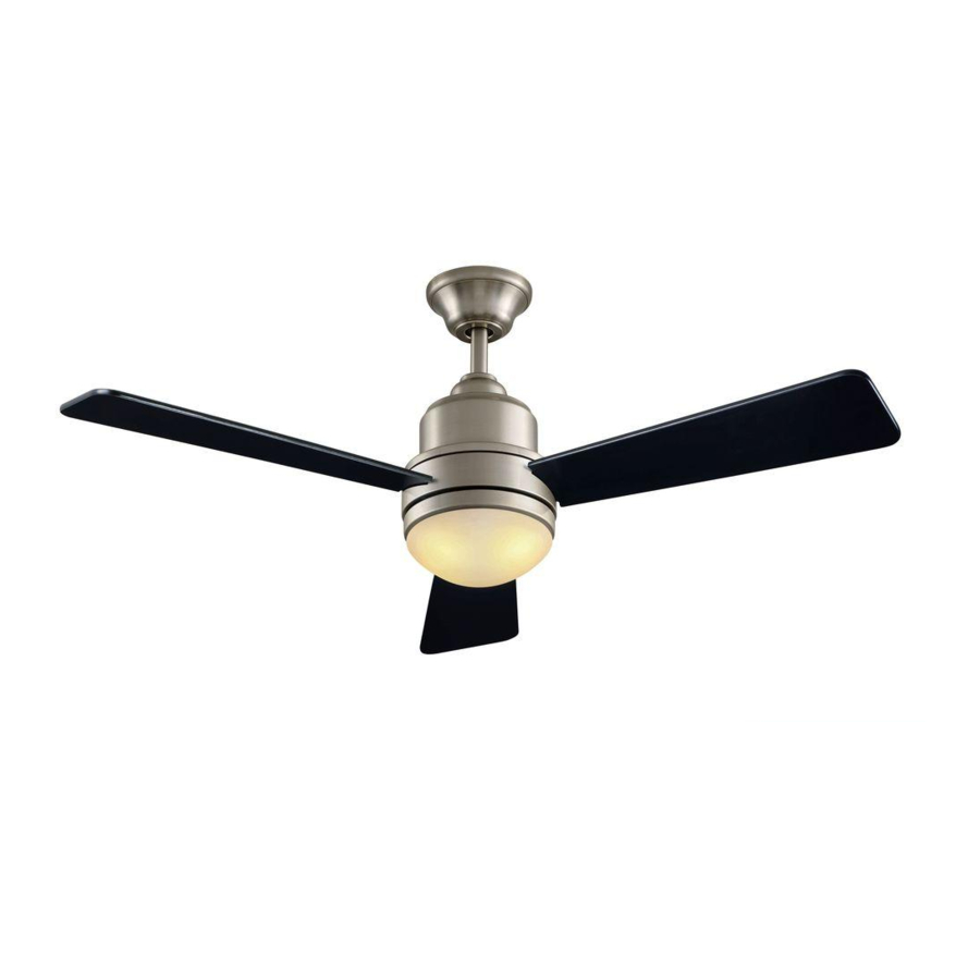
52” Trieste Thank you for purchasing this Hampton Bay ceiling fan. This product has been manufactured with the highest standards of safety and quality. The finish Ceiling Fan by Hampton Bay of this fan is weather resistant, but over time will naturally weather and fade. -
Page 3: Safety Rules 1
READ AND SAVE THESE INSTRUCTIONS Do not operate reversing switch while fan blades are in mo- To reduce the risk of electric shock, insure electricity tion. Fan must be turned off and blades stopped before re- has been turned off at the circuit breaker or fuse box versing blade direction. -
Page 4: Unpacking Your Fan
Unpack your fan and check the contents. You should have the following items: Blade attachment hardware Mounting Plate (inside canopy) Light Kit Assembly (9 Screws) Downrod and Ball Assembly Glass Mounting & Electrical Hardware Canopy Bulbs (2) (1 hanger pin, 1 locking pin, 3 plastic wire Decorative Motor Collar Cover Hand Unit/Receiver connectors) -
Page 5: Tools Required
LIGHTING FIXTURES MAY NOT BE ACCEPT- installation hanger bar as shown in Figure 4 ABLE FOR FAN SUPPORT AND MAY NEED TO (available at your Hampton Bay retailer). BE REPLACED. CONSULT A QUALIFIED ELEC- TRICIAN IF IN DOUBT. Installing Your Fan 3. -
Page 6: Hanging The Fan
Hanging the Fan the wiring inside the downrod. Insert the locking pin through the hole near the REMEMBER end of the bolt until it snaps into its turn pow- locked position, as noted in the circle inset er. Follow the steps below to hang your of Figure 7. -
Page 7: Making The Electrical Connections
Installing Fan to Making the Electrical the Electrical Box Connections REMEMBER to disconnect the power. If you feel you do not have enough electrical WHEN MOUNTING THE FAN ON A SLOPED wiring knowledge or experience, have your fan CEILING, THE STANDARD BALL/DOWNROD MOUNTING METHOD MUST BE USED. - Page 8 Finishing the Fan Connect the receiver white wire to the sup- ply white wire (neutral) wire using a wire Installation nut (Figure 8). After connecting the wires, spread them STANDARD CEILING MOUNTING apart so that the green and white wires are one side of the electrical box and the black WHEN USING THE STANDARD BALL/DOWNROD wire is on the other side.
-
Page 9: Blade Balancing
Attaching the Blade Balancing Fan Blades All blades are grouped by weight. Because nat- ural woods vary in density, the fan may wobble Insert the blade through the slot cut-off in even though the blades are weight matched. the center flywheel, align the three screw The following procedure should correct most holes in the blade with the screw holes in fan wobble. - Page 10 Installing the Light Connect the blue and white wires exiting the light kit adaptor with the black and white Kit/ Glass Bowl wires from the light kit assembly by engag- ing the molded adaptor plugs (blue to black; CAUTION - To reduce the risk of electrical white to white).
-
Page 11: Operating Your Fan 9
Speed settings for warm or cool weather depend on factors such as room size, ceil- ing height, number of fans, and so on. Warm weather - (Forward) A downward The fan shipped from the factory with the air flow creates a cooling effect as shown reversing switch positioned to circulate air in Figure 13. -
Page 12: Operating Your Remote
Operating the Fan: Remote Control Setting the Code Your fan is equipped with a remote control This unit has 16 different code combinations. Hi Key - High Speed To set the code, perform the following steps: to operate the speed and lights of your new Med Key - Medium Speed A. -
Page 13: Care Of Your Fan
Troubleshooting Care of Your Fan Here are some suggestions to help you Problem Solution maintain your fan. Fan will not start Check main and branch circuit fuses or breakers Because of the fan’s natural movement, Check line wire connections to the fan and switch wire connections in some connections may become loose. -
Page 14: Specifications 12
GROSS CUBE FAN SIZE SPEED VOLTS AMPS WATTS WEIGHT WEIGHT FEET 0.29 1584 21.2 52” 0.44 3234 18.7 Lbs 1.76 High 0.52 4575 These are approximate measures. They do not include Amps and Wattage used by the light kit. Distributed by Home Depot U.S.A., Inc. 2455 Paces Ferry Rd. -
Page 15: Warranty Information 13
You must present a copy of the original Hampton Bay also warrants that all other fan parts, excluding any glass or acrylic blades, to be free purchase receipt to obtain warranty service.