Table of Contents
Advertisement
Available languages
Available languages
Advertisement
Chapters
Table of Contents

Related Manuals for HAMPTON BAY 54" Tropics


Summary of Contents for HAMPTON BAY 54" Tropics
- Page 1 454 849 s/o 455 805 Tropics Tropics...
-
Page 2: Table Of Contents
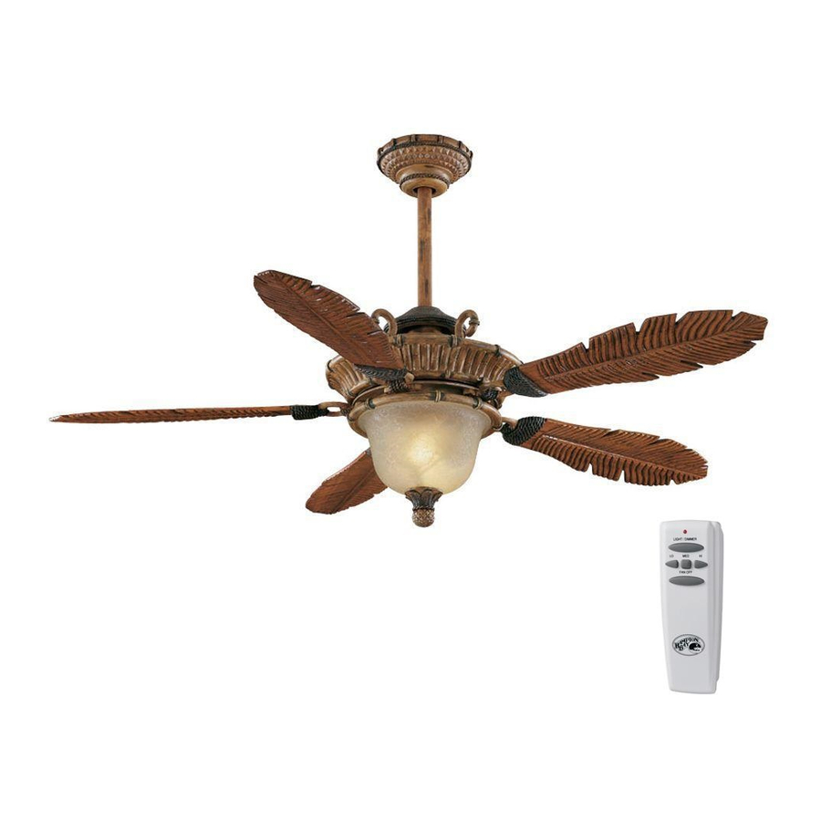
54” Tropics Thank you for purchasing this Hampton Bay ceiling fan. This product has been manufactured with the highest standards of safety and quality. The finish Ceiling Fan by Hampton Bay of this fan is weather resistant, but over time will naturally weather and fade. -
Page 3: Safety Rules 1
READ AND SAVE THESE INSTRUCTIONS To avoid personal injury or damage to the fan and To reduce the risk of electric shock, insure electricity other items, be cautious when working around or has been turned off at the circuit breaker or fuse box cleaning the fan. -
Page 4: Unpacking Your Fan
Unpack your fan and check the contents. You should have the following items: Blade attachment hardware 1. Slide-On Mounting Plate (inside Canopy) 8. Glass Bottom Cover (15 screws and lockwashers) 2. Downrod and Ball Assembly 9. Blade Bracket with Captive Screws (5) Mounting &... -
Page 5: Installing Your Fan 3
Figure 3 If there isn’t an existing outlet box, then read (available at your Hampton Bay retailer). the following instructions. Disconnect the power by removing fuses or turning off circuit breakers. - Page 6 Hanging the Fan Remove UL Listed Outlet Box REMEMBER to turn off the power. Mounting Screws Follow the steps below to hang your (supplied with fan properly. outlet box) NOTE: This fan is recommended for the Hook standard ceiling mounting using the downrod provided with this fan.
- Page 7 Installing Fan to Making the Electrical 7. Connect the blue wire (For Light) from the receiver unit to the blue wire from the fan. the Outlet Box Connections After wires are connected, carefully tuck them into the outlet box. Insert the receiver unit into 1.
- Page 8 Finishing the Fan Screws and Installation Lockwashers Support Plate WHEN USING THE STANDARD BALL/DOWN- ROD MOUNTING, THE TAB IN THE RING AT THE BOTTOM OF THE MOUNTING PLATE MUST Blade REST IN THE GROOVE OF THE HANGER BALL. Blade Bracket FAILURE TO PROPERLY SEAT THE TAB IN THE Figure 7 GROOVE COULD CAUSE DAMAGE TO WIRING.
- Page 9 BLADE BALANCING 4. Rotate the center flywheel until the blade bracket screw holes in the center flywheel All blades are grouped by weight. Because are visible from the cut-out in the light kit plate of the fan motor (Figure 8b). natural woods vary in density, the fan may wobble even though the blades are weight matched.
- Page 10 Attaching the Glass Shade CAUTION - To reduce the risk of electrical shock, disconnect the electrical supply circuit to the fan before installing light kit. Light Kit THE GLASS IS FRAGILE, USE CARE Plate Bulbs WHEN INSTALLING THE LIGHT KIT AND THE GLASS SHADE.
-
Page 11: Operating Your Fan 9
DO NOT WAIT FOR THE FAN TO STOP TO TO REDUCE RISK OF PERSONAL INJURY, PRESS THE REVERSE BUTTON. THE FAN WILL DO NOT BEND THE BLADE HOLDERS WHILE NOT REVERSE IF THE FAN IS NOT MOVING. INSTALLING, BALANCING THE BLADES OR CLEANING THE FAN. -
Page 12: Operating Your Remote Control
Setting the Code Installing Receiver This unit has 16 different code combinations. To A. Wire Connection: set the code, perform the following steps: Fan Green Wire ............... Bare Supply Wire A. Setting the code on the transmitter: a. Remove the battery cover. Press firmly Black Receiver Wire (AC IN L) ........ -
Page 13: Care Of Your Fan
Troubleshooting Care of Your Fan Here are some suggestions to help you Problem Solution maintain your fan. Fan will not start Check main and branch circuit fuses or breakers 1. Because of the fan’s natural movement, Check line wire connections to the fan and switch wire connections in some connections may become loose. -
Page 14: Specifications
GROSS CUBE FAN SIZE SPEED VOLTS AMPS WATTS WEIGHT WEIGHT FEET 0.33 1815 33.4 38.5 54” 0.49 3640 3.18 High 0.66 5985 These are approximate measures. They do not include Amps and Wattage used by the light kit. This equipment has been tested and found to comply with the limits for a Class B digital device, pursuant to Part 15 of the FCC Rules. These limits are designed to provide reasonable protection against harmful interference in a residential installation. -
Page 15: Warranty Information 13
You must present a copy of the original Hampton Bay also warrants that all other fan parts, excluding any glass or acrylic blades, to be free purchase receipt to obtain warranty service. - Page 16 Tropics de 54” Gracias por comprar este ventilador de techo de Hampton Bay. Este producto se ha fabricado con las normas de seguridad y calidad más altas. El acabado Ventilador de techo de Hampton Bay de este ventilador es resistente a la intemperie, pero con el tiempo, exhibirá...
-
Page 17: Normas De Seguridad
LEE LAS INSTRUCCIONES Y GUÁRDALAS Evita colocar objetos en la trayectoria de las aspas. Para disminuir el riesgo de descarga eléctrica, asegúrate de que la electricidad ha sido apagada en el cortacircuitos o la caja de Para evitar lesiones, o daños al ventilador y otros objetos; ten fusibles antes de comenzar la instalación. -
Page 18: Cómo Desempacar El Ventilador 2
Desempaca tu ventilador y revisa el contenido. Deberá tener las siguientes piezas: Herrajes de montaje de aspas 1. Placa de montaje deslizante (dentro de la 8. Cubierta inferior del vidrio (15 tornillos y arandelas de seguridad) cubierta) 9. Soportes de aspa con tornillos fijos (5) Herrajes de montaje y electricidad 2. -
Page 19: Cómo Instalar El Ventilador
Figura 3 (disponible en cortacircuitos. la tienda minorista local de Hampton Bay). Asegura la caja eléctrica directamente a la estructura del edificio. Usa sujetadores y materiales de construcción apropiados. La Figura 1 caja eléctrica y su soporte deben sostener... - Page 20 Cómo colgar el ventilador Quitar Caja eléctrica RECUERDA desconectar corriente. aprobada Tornillos de montaje por UL Sigue estos pasos para colgar correctamente tu (incluidos con ventilador. la caja eléctrica) NOTA: Se recomienda instalar este ventilador Gancho en un techo estándar usando el tubo bajante Deslizar el soporte suministrado con el ventilador.
- Page 21 Cómo hacer las Cómo instalar el ventilador la unidad receptora al cable negro del ensamblado del ventilador. en la caja eléctrica conexiones eléctricas 7. Conecta el cable azul (Para la Luz) de la unidad receptora al cable azul del ventilador. 1.
- Page 22 Finalizar la instalación CIRCUITO DE SUMINISTRO Tornillos y arandelas del ventilador de seguridad Placa de soporte CUANDO USES MONTAJE DE TUBO BAJANTE Y BOLA ESTÁNDAR, LA PESTAÑA RECEPTOR EN EL ARO EN LA PARTE INFERIOR DE LA Aspa REMOTO PLACA DE MONTAJE DEBE ENCAJAR EN LA Soporte de aspa RANURA DE LA BOLA DE SOPORTE.
- Page 23 COMPENSACIÓN DE LAS 4. Gira el volante central hasta que a través de la abertura de la placa superior del kit de ASPAS PARA REDUCIR EL RIESGO DE LESIONES luces del motor, puedas ver los orificios de PERSONALES, NO DOBLAR LOS SOPORTES tornillos del soporte del aspa en el volante DE LAS ASPAS DURANTE LA INSTALACIÓN, Todas las aspas se agrupan por peso.
- Page 24 Cómo montar la pantalla de vidrio PRECAUCIÓN – Para disminuir el riesgo de descarga eléctrica, desconecta el circuito de energía del ventilador antes de instalar el kit de luces. Placa del Bombillas EL VIDRIO ES FRÁGIL, TEN CUIDADO kit de luces AL INSTALAR EL KIT DE LUCES Y LA Vástago PANTALLA DE VIDRIO.
-
Page 25: Cómo Operar El Ventilador
OPRIME EL BOTÓN DE REVERSA CUANDO EL PARA REDUCIR EL RIESGO DE LESIONES VENTILADOR TODAVÍA ESTÁ EN MOVIMIENTO. PERSONALES, NO DOBLAR LOS SOPORTES SI EL VENTILADOR NO ESTÁ EN MOVIMIENTO DE LAS ASPAS DURANTE LA INSTALACIÓN, NO CAMBIARÁ DE DIRECCIÓN. COMPENSACIÓN ASPAS LIMPIEZA DEL VENTILADOR. -
Page 26: Cómo Manejar El Control Remoto 10
Cómo instalar el receptor Cómo configurar el código Esta unidad tiene 16 combinaciones de códigos A Conexión de cable: diferentes. Para configurar el código, sigue los Cable verde del ventilador ..........Cable de suministro desnudo siguientes pasos: A. Configurar el código del transmisor: Cable negro del receptor (CA EN L) ...... -
Page 27: Cuidado Del Ventilador
Solución de problemas Cuidado del ventilador Aquí tienes algunas sugerencias para el Problema Solución mantenimiento de tu ventilador. El ventilador no Verifica fusibles o disyuntores principales y secundarios. 1. Debido al movimiento natural del ventilador, enciende Verifica conexiones de cables en línea al ventilador y conexiones de cables algunas conexiones pueden... -
Page 28: Especificaciones 12
PIES PESO PESO PIES TAMAÑO VELOCIDAD VOLTIOS AMPERIOS VATIOS CÚB. X NETO BRUTO CÚB. MIN. Baja 0.33 1815 38.5 54” Media 0.49 3640 33.4 Lb 3.18 Alta 0.66 5985 Estas medidas son aproximadas. No incluyen ni el amperaje ni el vataje consumido por el kit de luces. Este equipo ha sido comprobado y se determinó... -
Page 29: Información De La Garantía
Hampton Bay garantiza de por vida, a partir de la fecha de compra por el comprador original, que el motor del ventilador no presenta defectos de fabricación ni de material desde la fecha de salida de la Usted debe presentar una copia del fábrica.