Motorola RFS7000 Series System Reference Manual
Rf switch
Hide thumbs
Also See for RFS7000 Series:
- Reference manual (732 pages) ,
- Troubleshooting manual (60 pages) ,
- Installation manual (31 pages)
Table of Contents
Advertisement
Quick Links
Advertisement
Table of Contents

Related Manuals for Motorola RFS7000 Series


Summary of Contents for Motorola RFS7000 Series
- Page 1 RFS7000 Series RF Switch System Reference Guide...
- Page 2 MOTOROLA and the Stylized M Logo are registered in the US Patent & Trademark Office. Symbol is a registered trademark of Symbol Technologies, Inc. All other product or service names are the property of their respective owners. © Motorola, Inc. 2008. All rights reserved.
-
Page 3: About This Guide
Screens and windows pictured in this guide are samples and can differ from actual screens. Documentation Set The documentation set for the RFS7000 Series Switch is partitioned into the following guides to provide information for specific user needs. RFS7000 Installation Guide - describes the basic setup and configuration required to transition to more advanced •... -
Page 4: Notational Conventions
RFS7000 Series Switch System Reference Guide Notational Conventions The following additional notational conventions are used in this document: Italics are used to highlight the following: • Chapters and sections in this and related documents Dialog box, window and screen names... -
Page 5: Table Of Contents
Contents Chapter 1. Overview Hardware Overview ..........1-1 Physical Specifications . - Page 6 RFS7000 Series Switch System Reference Guide Power Save Polling......... 1-17 QoS .
- Page 7 Table of Contents Viewing the Ports Statistics........3-12 Detailed Port Statistics .
- Page 8 RFS7000 Series Switch System Reference Guide Configuring Authentication Types ......4-33 Configuring Different Encryption Types .
- Page 9 Table of Contents Viewing Access Port Status ......... .4-117 Viewing Adopted Access Ports .
- Page 10 RFS7000 Series Switch System Reference Guide Layer 3 Mobility ........... .5-46 Configuring Layer 3 Mobility .
- Page 11 Table of Contents Reviewing ACL Statistics.........6-31 Configuring NAT Information .
- Page 12 RFS7000 Series Switch System Reference Guide Configuring Enhanced Beacons and Probes.......6-96 Configuring the Beacon Table .
- Page 13 Table of Contents xiii Reviewing Panic Snapshots ......... . 8-17 Viewing Panic Details.
- Page 14 RFS7000 Series Switch System Reference Guide...
-
Page 15: Hardware Overview
Overview The RFS7000 switch is a centralized management solution for wireless networking. It connects to non-legacy access ports through L2 or L3 (L2 is preferable, if the situation allows it). Access ports function as radio antennas for data traffic management and routing. System configuration and intelligence for the wireless network resides with the switch. -
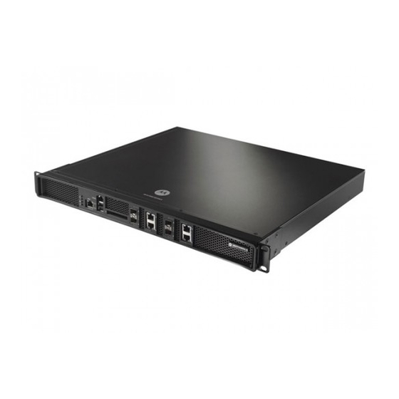
Page 16: Physical Specifications
Overview Access ports do not have software or firmware upon initial receipt from the factory. When the access port is first powered on and cleared for the network, the switch initializes the access port and installs a small firmware file automatically. Installation and firmware upgrades are automatic and transparent. 1.1.1 Physical Specifications The physical dimensions and operating parameters of the switch include: Width... -
Page 17: Cabling Requirements
Again, a power cord is not supplied with the switch. Use only a correctly rated power cord certified for the country of operation. Initial installation instructions are described in the RFS7000 Series Switch Installation Guide included with the switch. -
Page 18: System Status Led Codes
Overview 1.1.2 System Status LED Codes The RFS7000 has four vertically-stacked LEDs on its front panel. Each of the switch’s Gigabit Ethernet ports have two status LEDs. These LEDs display two colors (green & amber), and three lit states (solid, blinking, and off). - Page 19 Overview Switch Status (Redundant System) System Status 1 LED System Status 2 LED Event Power off Green Solid No redundancy feature enabled Redundant system failed over and adopting Green Blinking Green Solid ports Alternating Green Blinking Green Blinking Redundant system not failed over. &...
-
Page 20: Rj-45 Gigabit Ethernet Leds
Overview 1.1.2.2 RJ-45 Gigabit Ethernet LEDs RJ-45 Port Speed LED Port Speed LED Event 10 Mbps Green Solid 100 Mbps Green Blinking 1000 Mbps Amber Blinking Port fault RJ-45 Port Status LED Port Status LED Event No link or administratively shut down Green Solid Link present Green Blinking... -
Page 21: Out Of Band Management Port Leds
Overview SFP Port Speed LED Port Speed LED Event Green Blinking 1000 Mbps Amber Blinking Module or Tx/Rx fault loss SFP Port Status LED Port Status LED Event No link or administratively shut down Green Solid Link present / Operational Amber Blinking Module or Tx/Rx fault loss 1.1.2.4 Out of Band Management Port LEDs... -
Page 22: Infrastructure Features
• Access Port Support NOTE The Motorola RF Management Software is a recommended utility to plan the deployment of the switch and view its configuration once operational in the field. Motorola RFMS can help optimize the positioning and configuration of a switch in respect to a WLAN’s MU throughput requirements and can help detect rogue... -
Page 23: Configuration Management
Overview 1.2.1.3 Configuration Management The system supports redundant storage of configuration files to protect against corruption during a write operation and ensures (at any given time) a valid configuration file exists. If a configuration file has failed to completely execute, it is rolled back and the pre-write file is used. Text Based Configuration The configuration is stored in a human readable format (a set of CLI commands). -
Page 24: Process Monitor
1-10 Overview The log message format is similar to the format used by syslog messages (RFC 3164). Log messages include message severity, source (facility), the time the message was generated and a textual message describing the situation triggering the event. For more information on using the switch logging functionality, see Configuring System Logging on page 8-9. -
Page 25: Password Recovery
1-11 Overview • The switch can be configured to provide NTP services to NTP clients. • The switch can provide NTP support for user authentication. • Secure Network Time Protocol (SNTP) clients can be configured to synchronize switch time with an external NTP server. -
Page 26: Physical Layer Features
1-12 Overview The switch can be discovered using one of the following mechanisms: • DHCP • Switch fully qualified domain name (FQDN) • Static IP addresses The benefits of an AAP deployment include: • Centralized Configuration Management & Compliance - Wireless configurations across distributed sites can be centrally managed by the wireless switch or cluster. -
Page 27: Proxy-Arp
1-13 Overview 1.2.2.3 Proxy-ARP Proxy ARP is provided for MU's in PSP mode whose IP address is known. The WLAN generates an ARP reply on behalf of a MU, if the MU's IP address is known. The ARP reply contains the MAC address of the MU (not the MAC address of switch). -
Page 28: Idm (Identity Driven Management)
1-14 Overview 1.2.2.5 IDM (Identity Driven Management) Radius authentication is performed for all protocols using a Radius-based authentication scheme such as EAP. Identity driven management is provided using a Radius client. The following IDMs are supported: • User based SSID authentication — Denies authentication to MUs if associated to a SSID configured differently in their Radius server. -
Page 29: Wireless Capacity
1-15 Overview Detector APs Configure an AP in either – Data mode (the regular mode) or Detector mode. In Detector mode, the AP scans all channels at a configurable rate and forwards received beacons the switch. The switch uses the received information to establish a receive signal strength baseline over a period of time and initiates self-healing procedures (if necessary). -
Page 30: Wireless Roaming
1-16 Overview MU Balancing Across Multiple APs As per the 802.11 standard, AP and MU association is a process conducted independently of the switch. 802.11 provides message elements used by the MU firmware to influence the roaming decision. The switch implements the following MU load balancing techniques: •... -
Page 31: Power Save Polling
1-17 Overview PMKs among themselves. This allows an MU to roam to an AP that it has not previously visited and reuse a PMK from another AP to skip the 802.1x authentication. Interswitch Layer 2 Roaming An associated MU (connected to a particular wireless switch) can roam to another access port connected to a different wireless switch. -
Page 32: Wireless Layer 2 Switching
1-18 Overview 802.11e QoS 802.11e enables real-time audio and video streams to be assigned a higher priority over regular data. The switch supports the following 802.11e features: • Basic WMM • WMM Linked to 802.1p Priorities • WMM Linked to DSCP Priorities •... -
Page 33: Automatic Channel Selection
1-19 Overview 1.2.2.14 Automatic Channel Selection Automatic channel selection works as follows: 1. When a new AP is adopted, it scans each channel. However, the switch does not forward traffic at this time. 2. The switch then selects the least crowded channel based on the noise and traffic detected on each channel. - Page 34 1-20 Overview • Unicast From Mobile Unit – Frames are decrypted, converted from 802.11 to 802.3 and switched to the wired side of the VLAN dynamically assigned to the mobile device. If the destination is another mobile device on the wireless side, the frame is encrypted and switched over the air. •...
-
Page 35: Wired Switching
1-21 Overview 1.2.3 Wired Switching The switch includes the following wired switching features: • DHCP Servers • DDNS • VLAN Enhancements • Interface Management 1.2.3.1 DHCP Servers Dynamic Host Configuration Protocol (DHCP) allows hosts on an IP network to request and be assigned IP addresses, and discover information about the network to which they are attached. -
Page 36: Interface Management
1-22 Overview 1.2.3.4 Interface Management The switch permits a physical interface to Auto Negotiate, Full Duplex or Half Duplex. The switch also allows: • Manual bandwidth configuration of a physical interface to 10/100/1000Mbps. This is only permitted if duplex is not set to Auto Negotiate. •... -
Page 37: Encryption And Authentication
KeyGuard is a proprietary dynamic WEP solution. Motorola (upon hearing of the vulnerabilities of WEP) developed a non standard method of rotating keys to prevent compromises. Basically, KeyGuard is TKIP without the message integrity check MIC. KeyGuard is proprietary to Motorola MUs only. For information on configuring KeyGuard for a target WLAN, see Configuring WEP 128 / KeyGuard on page 4-51. -
Page 38: Secure Beacon
1-24 Overview 802.1x EAP 802.1x EAP is the most secure authentication mechanism for wireless networks and includes EAP-TLS, EAP-TTLS and PEAP. The switch is a proxy for Radius packets. An MU does a full 802.11 authentication and association and begins transferring data frames. The switch realizes the MU needs to authenticate with a Radius server and denies any traffic not Radius related. -
Page 39: Wips
Radius Server. 1.2.5.8 WIPS The Motorola Wireless Intrusion Protection System (WIPS) monitors for the presence of unauthorized rogue devices. Unauthorized attempts to access the WLAN is generally accompanied by anomalous behavior as intruding MUs try to find network vulnerabilities. Basic forms of this behavior can be monitored and reported without needing a dedicated WIPS. -
Page 40: Rogue Ap Detection
• Motorola RFMS Support NOTE The Motorola RF Management Software is recommended to plan the deployment of the switch. Motorola RFMS can help optimize the positioning and configuration of a switch in respect to a WLAN’s MU throughput requirements and can help detect rogue devices. -
Page 41: Acls
With this most recent switch firmware release, the switch can provide rogue device detection data to the Motorola RF Management software application (or Motorola RFMS). Motorola RFMS uses this data to refine the position and display the rogue on a site map representative of the physical dimensions of the actual radio coverage area of the switch. -
Page 42: Firewall
Intranet pass through the firewall, which examines each message and blocks those that do not meet the specified security criteria. Motorola’s RFS7000 offers a hardware assisted stateful firewall that can route traffic at line rate (4 Gbps, full duplex). Some common attacks checked by a RFS7000 supported firewall include: •... -
Page 43: Certificate Management
1-29 Overview • TCP Bad Sequence number Apart from detecting the above attacks, the firewall also performs sanity checks on every packet. These sanity checks can drop a packet if the packet is malformed. A log message is generated whenever a packet gets dropped due to these sanity checks. -
Page 44: Access Port Support
1-30 Overview 1.2.5.16 NAC There is an increasing proliferation of insecure devices (laptops, mobile computers, PDA, smart-phones) accessing WiFi networks. These devices often lack proper anti-virus software and can potentially infect the network they access. Device compliance per an organization’s security policy must be enforced using NAC. A typical security compliance check entails verifying the right operating system patches, anti-virus software etc. -
Page 45: Accessing The Switch Web Ui
Switch Web UI Access & Image Upgrades 2.1 Accessing the Switch Web UI 2.1.1 Web UI Requirements The switch Web UI is accessed using Internet Explorer version5.5 (or later) and SUN JRE (Java Runtime Environment) 1.5 (or later). Refer to the Sun Microsystems Web site for information on downloading JRE. NOTE To successfully access the switch Web UI through a firewall, UDP port 161 must be open in order for the switch’s SNMP backend to function. -
Page 46: Connecting To The Switch Web Ui
This warning screen will continue to display on future login attempts until a self-signed certificate is implemented. Motorola recommends only using the default certificate for the first few login attempts until a self-signed certificate can be generated. -
Page 47: Switch Password Recovery
Switch Web UI Access & Image Upgrades switch, view the status of the switch’s Ethernet connections and view switch CPU and memory utilization statistics. NOTE The chapters within this System Reference Guide are arranged to be complimentary with the main menu items in the menu tree of the Web UI. Refer to this content to configure switch network addressing, security and diagnostics as required. - Page 48 Installing the System Iamge...
-
Page 49: Viewing The Switch Interface
Switch Information This chapter describes the Switch main menu information used to configure the RFS7000. This chapter consists of the following sections: • Viewing the Switch Interface • Viewing Switch Port Information • Viewing Switch Configurations • Viewing Switch Firmware Information •... -
Page 50: Viewing The Switch Configuration
Switch Information NOTE The Motorola RF Management Software is a recommended utility to plan the deployment of the switch and view its interface statistics once operational in the field. Motorola RFMS can help optimize the positioning and configuration of a switch (and its associated radios) in respect to a WLAN’s MU throughput... - Page 51 Firmware Displays the current firmware version running on the switch. This version should be periodically compared to the most recent version available on the Motorola Web site, as versions with increased functionality are periodically released...
-
Page 52: Viewing Dashboard Details
Switch Information AP Licenses Displays the number of access port licenses currently available for the switch. This value represents the maximum number of access ports the switch is licensed to adopt. Date (MM/DD/YYYY) Displays the day, month and year currently used with the switch. Time Displays the time of day used by the switch. - Page 53 Switch Information Dashboard screen displays the current health of the switch and is divided into the following fields: • Alarms • Ports • Environment • CPU Memory • File Systems Apart from the sections mentioned above, it also displays the following: Displays the Redundancy State of the switch.
-
Page 54: Viewing Switch Statistics
Switch Information Displays the switch uptime. The Uptime is the current operational time defined within the System Name field. Uptime is the cumulative time since the switch was rebooted or lost power. 1. Refer to the Alarms field for details of all the unacknowledged alarms generated during the past 48 hours. - Page 55 Switch Information 2. Click the Switch Statistics tab at the top of the Switch screen. 3. Refer to the following read-only information about associated MUs: Number of MUs Displays the total number of MUs currently associated to the Associated switch. Number of APs Displays the total number of access ports currently adopted by the Adopted...
-
Page 56: Viewing Switch Port Information
Switch Information Average Noise Displays the average RF noise for all MUs associated with the selected WLAN. MU noise for the last 30 seconds is displayed in black and the number in blue represents MU noise for the last hour. Average SNR (dB) Displays the average Signal to Noise Ratio (SNR) for all MUs associated with the switch. - Page 57 Switch Information 2. Select the Configuration tab to display the following read-only information: Name Displays the port name. Aggregation Displays the Channel Group defined for the port (if any). The Membership switch bundles individual Ethernet links (over the selected channel) into a single logical link that provides bandwidth between the switch and another switch or host.
-
Page 58: Editing The Port Configuration
3-10 Switch Information 3.2.1.1 Editing the Port Configuration To modify the port configuration: 1. Select a port from the table displayed within the Configuration tab. 2. Click the Edit button. Port Change Warning screen displays, stating any change to the port setting could disrupt access to the switch. -
Page 59: Viewing The Ports Runtime Status
3-11 Switch Information Medium Displays the current (read-only) connection medium used by this port. Read-only details about the port’s cabling connection also display within the Edit screen. This information should be used to help assess what configuration should be set for this port. 5. -
Page 60: Viewing The Ports Statistics
3-12 Switch Information Displays the maximum transmission unit (MTU) setting configured on the port. The MTU value represents the largest packet size that can be sent over a link. The MTU is determined by the underlying network, but must be taken into account at the IP level. IP packets (which can be up to 64K bytes each) must be packaged into lower- level packets of the appropriate size for the underlying network(s) and re-assembled on the other end. -
Page 61: Detailed Port Statistics
3-13 Switch Information Packets Out Displays the total number of packets transmitted (sent) by the port. A low value could be an indication of a network problem. Packets Out Dropped Displays the total number of transmitted packets dropped. A high value may be an indication of network issues. - Page 62 3-14 Switch Information Input Packets Dropped Displays the number of received packets dropped at the interface by the input Queue of the hardware unit /software module associated with the interface. Packets are dropped when the input Queue of the interface is full or unable to handle incoming traffic. Input Packets Error Displays the number of received packets with errors at the interface.
-
Page 63: Viewing The Port Statistics Graph
3-15 Switch Information 3.2.3.2 Viewing the Port Statistics Graph The switch continuously collects data for port statistics. Even when the port statistics graph is closed, data is still tallied. Periodically display the port statistics graph for assessing the latest information. To view a detailed graph for a port: 1. -
Page 64: Viewing Switch Configurations
NOTE To view the entire switch configuration using SNMP, the switch CLI provides a better medium to review the entire switch configuration. NOTE The Motorola RF Management Software is a recommended utility to plan the deployment of the switch and view its configuration once operational in the field. -
Page 65: Viewing The Detailed Contents Of A Config File
3-18. 3.3.1 Viewing the Detailed Contents of a Config File The View screen displays the entire contents of a configuration file. Motorola recommends a file be reviewed carefully before it is designation as the switch startup configuration. 1. Select a configuration file from the Configuration screen. -
Page 66: Transferring A Config File
3-18 Switch Information 2. Click the View button to see the contents of the selected configuration file. 3. The Main screen displays the contents of the configuration file. Use the up and down navigation facilities on the right-hand side of the screen to view the entire file. 4. - Page 67 3-19 Switch Information To transfer the contents of a configuration file: 1. Click the Transfer Files button on the bottom of the Configuration screen. 2. Refer to the Source field to define the location and address information for the source config file. From Select the location representing the source file’s current location using the...
- Page 68 3-20 Switch Information File Browser (icon) If the target specified is Wireless Switch, click the File Browser icon to specify the target file’s location on the switch. The target location can be any of the three file systems on the switch: Flash, System or NVRAM.
-
Page 69: Viewing Switch Firmware Information
3-21 Switch Information 3.4 Viewing Switch Firmware Information The switch can store two software versions. Information about the two versions displays within the Firmware screen. The Version column displays the version string. The Build Time is the date and time each version was generated. -
Page 70: Editing The Switch Firmware
3-22 Switch Information Built Time Displays the time the version was created (built). Do not confuse the Built Time with the time the firmware was last loaded on the switch. Install Time The Install Time is the time this version was loaded with on the switch. -
Page 71: Updating The Switch Firmware
3-23 Switch Information This firmware version will now be invoked after the next reboot of the switch. 5. Refer to the Status field for the current state of the requests made from the applet. Requests are any “SET/GET” operation from the applet. The Status field displays error messages if something goes wrong in the transaction between the applet and the switch. - Page 72 3-24 Switch Information a. Use to get the firmware update from a File Transfer Protocol (FTP) server. A user account must be established on the FTP server specified for the firmware update. b. Use TFTP to get the firmware update from a Trivial File Transfer Protocol (TFTP) server. 6.
-
Page 73: Switch File Management
3-25 Switch Information 3.5 Switch File Management Use the File Management screen to transfer configuration file to and from the switch and review the files available. The File Management screen consists of the following tabs: • Transfer Files • File System 3.5.1 Transferring Files Use the Transfer Files... -
Page 74: Transferring A File From Wireless Switch To Wireless Switch
3-26 Switch Information 2. Refer to the Source field to specify the details of the source file. From Use the From drop-down menu to select the source file’s current location. The options include Wireless Switch and Server. The following transfer options are possible: •... -
Page 75: Transferring A File From A Wireless Switch To A Server
3-27 Switch Information 3.5.1.2 Transferring a file from a Wireless Switch to a Server To transfer a file from the switch to a Server: 1. Refer to the Source field to specify the source file. Use the From drop-down menu and select Wireless Switch. - Page 76 3-28 Switch Information 2. Provide the name of the File. 3. Use the Using drop-down menu to configure whether the file transfer is conducted using FTP, TFTP or HTTP. FTP transfers require a valid user ID and password. 4. Enter an IP Address of the server receiving the configuration file.
-
Page 77: Viewing Files
3-29 Switch Information 3.5.2 Viewing Files Use the File System tab to review the files available to the switch. The switch maintains the following file types: • flash • nvram • system • Compact Flash • USB 1 • USB 2 Transfer files between the switch and the server from any one of the above mentioned locations. -
Page 78: Configuring Automatic Updates
Enable this option for either the firmware, configuration file or cluster configuration file. Motorola recommends leaving this setting disabled if a review of a new file is required before it is automatically uploaded by the switch. - Page 79 3-31 Switch Information 2. Refer to the Switch Configuration field to enable and define the configuration for automatic configuration file updates. If enabled, the located (updated) configuration file will be used with the switch the next time the switch boots Enable Select the Enable...
-
Page 80: Viewing The Switch Alarm Log
3-32 Switch Information 4. Refer to the Firmware field to enable and define the configuration for automatic firmware updates. If enabled, the located (updated) switch firmware is used with the switch the next time the switch boots. Enable Select the Enable checkbox to allow an automatic firmware update when a new (updated) version is detected (upon the boot of... - Page 81 3-33 Switch Information 1. Select Switch > Alarm Log from the main menu tree. 2. Select either of the two available filter options to view alarm log information: View By Page Select the View By Page radio button to view alarm log information on a per page basis.
-
Page 82: Viewing Alarm Log Details
3-34 Switch Information Severity Displays the severity level of the event. Use this (non numerical and verbal) description to assess the criticality of the alarms. Severity levels include: • Critical • Major • Warning • Informational • Normal Module Name Displays the module name that triggered this alarm. - Page 83 3-35 Switch Information 2. Select an alarm and click the Details button. 3. Refer to the Alarm Details Alarm Message for the following information: Description Displays the details of the alarm log event. This information can be used in conjunction with the Solution Possible Causes items to troubleshoot the event and determine how the event can...
-
Page 84: Viewing Switch Licenses
License Key Enter the license key required to install a particular feature. The license key is provided when you supply the switch serial number to Motorola support. Feature Name Enter the name of the feature you wish to install/upgrade using the license. -
Page 85: How To Use The Filter Option
3-37 Switch Information 3.9 How to use the Filter Option Use the Filter Option to sort the display details of screen that employ the filtering option as a means of sorting how data is displayed within the screen. 1. Click the Show Filtering Option to expand the Filter Option zone, whenever it appears in any screen. - Page 86 3-38 Switch Information...
-
Page 87: Chapter 4. Network Setup
Network Setup This chapter describes the Network Setup menu information used to configure the switch. This chapter consists of the following switch Network configuration activities: • Displaying the Network Interface • Viewing Network IP Information • Viewing and Configuring Layer 2 Virtual LANs •... -
Page 88: Displaying The Network Interface
Network Setup 4.1 Displaying the Network Interface The main Network interface displays a high-level overview of the configuration (default or otherwise) as defined within the Network main menu. Use the information to determine if items require additional configuration using the sub-menu items under the main Network menu item. NOTE When the switch’s configuration is successfully updated (using the Web UI), the effected screen is closed without informing the user their change was successful. - Page 89 Network Setup 2. Refer to the following information to discern if configuration changes are warranted: DNS Servers Displays the number of DNS Servers configured thus far for use with the switch. For more information, see Viewing Network IP Information on page 4-4.
-
Page 90: Viewing Network Ip Information
Network Setup 4.2 Viewing Network IP Information Use the Internet Protocol screen to view and configure network associated IP details. The Internet Protocol screen contains tabs supporting the following configuration activities: • Configuring DNS • Configuring IP Forwarding • Viewing Address Resolution 4.2.1 Configuring DNS Use the Domain Name System... -
Page 91: Adding An Ip Address For A Dns Server
Network Setup 4. Select an IP Address from the table and click the Delete button to remove the selected entry from the list. 5. Click the button to display a screen used to add another domain name server. For more information, see Adding an IP Address for a DNS Server on page 4-5. -
Page 92: Configuring Ip Forwarding
Network Setup 2. Select the Domain Look Up checkbox to enable the switch to query domain name servers to resolve domain names to IP addresses. NOTE The look up order is determined by the order of the servers within Domain Name System tab. -
Page 93: Adding A New Static Route
Network Setup Subnet Mask Displays the mask used for destination subnet entries. The Subnet Mask is the IP mask used to divide internet addresses into blocks (known as subnets). A value of 255.255.255.0 will support 256 IP addresses. Gateway Address Displays the IP address of the Gateway used to route the packets to the specified destination subnet. -
Page 94: Viewing Address Resolution
Network Setup 2. In the Destination Subnet field, enter an IP address to route packets to a specific destination address. 3. Enter a subnet mask for the destination subnet in the Subnet Mask field. The Subnet Mask is the IP mask used to divide internet addresses into blocks known as subnets. A value of 255.255.255.0 support 256 IP addresses. -
Page 95: Viewing And Configuring Layer 2 Virtual Lans
Network Setup 4. Click the Clear button to remove the selected ARP entry if no longer usable. 4.3 Viewing and Configuring Layer 2 Virtual LANs A virtual LAN (VLAN) is similar to a Local Area Network (LAN), however devices do not need to be connected to the same segment physically. -
Page 96: Editing The Details Of An Existing Vlan
4-10 Network Setup Mode It can be either Access or Trunk. • Access– This ethernet interface accepts packets only form the native VLANs. • Trunk–The Ethernet interface allows packets from the given list of VLANs you add to the trunk. Native VLAN Displays the tag assigned to the native VLAN. -
Page 97: Viewing And Configuring Ports By Vlan
4-11 Network Setup 5. Use the Edit screen to modify the following: Name Displays a read only field with the name of the port to which the VLAN is associated. Mode Use the drop-down menu to select the mode. It can be either: •... -
Page 98: Editing A Vlan By Port Designation
4-12 Network Setup VLAN details display within the VLANs by Port tab. 3. Refer to the following information as displayed within the VLANs by Port tab: VLAN Displays the name of each VLAN configured on the switch. The VLAN and columns display the VLAN association status of each VLAN on the switch. -
Page 99: Configuring Switch Virtual Interfaces
4-13 Network Setup 3. Highlight an existing VLAN and click the Edit button. The system displays a Port VLAN Change Warning message. Be advised, changing VLAN designations could disrupt access to the switch. 4. Click to continue. A new window displays wherein the VLAN assignments can be modified for the selected VLAN. -
Page 100: Configuring The Virtual Interface
4-14 Network Setup Use the Switch Virtual Interfaces screen to view and configure VLAN interfaces. This screen contains two tabs supporting the following activities: • Configuring the Virtual Interface • Viewing Virtual Interface Statistics 4.4.1 Configuring the Virtual Interface Use the Configuration screen to view and configure virtual interface details. -
Page 101: Adding A Virtual Interface
4-15 Network Setup Management A green checkmark within this column defines this VLAN as Interface currently used by the switch. This designates the interface settings used for global switch settings in case of conflicts. For example, if multiple SVIs are configured with DHCP enabled on each, the switch could have multiple domain names assigned from different DHCP servers The one assigned over the selected Management Interface would be the only one used by the switch. -
Page 102: Modifying A Virtual Interface
4-16 Network Setup 5. Provide a Description for the VLAN, representative of the VLAN’s intended operation within the switch managed network. 6. The Primary IP Settings field consists of the following: a. Select Use DHCP to obtain IP Address automatically to allow DHCP to provide the IP address for the virtual interface. -
Page 103: Viewing Virtual Interface Statistics
4-17 Network Setup 2. Select the Configuration tab and click the Edit button. The screen displays with the name of the VLAN displayed in the upper left-hand side. The VLAN ID cannot be modified and should be used to associate the VLAN ID with the description and IP address assignments defined. - Page 104 4-18 Network Setup 2. Select the Statistics tab. 3. Refer to the following to assess the network throughput of existing virtual interfaces: Name Displays the user defined interface name. The corresponding statistics are displayed along the row. The statistics are the total traffic to the interface since its creation.
- Page 105 4-19 Network Setup Packets In Error Displays the number of error packets coming into the interface. It includes: • Runt frames — Packets shorter than the minimum Ethernet frame length (64 bytes). • CRC errors — The Cyclical Redundancy Check (CRC) is the 4 byte field at the end of every frame the receiving station uses to interpret if the frame is valid.
-
Page 106: Viewing Virtual Interface Statistics
4-20 Network Setup 4.4.2.1 Viewing Virtual Interface Statistics To view detailed virtual interface statistics: 1. Select a virtual interface from the Statistics tab. 2. Click the Details button. 3. The Interface Statistics screen displays the following granular content for the selected interface: Name Displays the title of the logical interface selected. -
Page 107: Viewing The Virtual Interface Statistics Graph
4-21 Network Setup Output Unicast Displays the number of unicast packets (packets directed towards Packets a single destination address) transmitted from the interface. Output NonUnicast Displays the number of unicast packets transmitted from the Packets interface. Output Total Packets Displays the total number of packets transmitted from the interface. - Page 108 4-22 Network Setup NOTE Do not select more than four parameters at any given time. 4. Refer to the Status field for the current state of the requests made from applet. This field displays error messages if something goes wrong in the transaction between the applet and the switch. 5.
-
Page 109: Viewing And Configuring Switch Wlans
4-23 Network Setup 4.5 Viewing and Configuring Switch WLANs A wireless LAN (WLAN) is a local area network (LAN) without wires. WLANs transfer data through the air using radio frequencies instead of cables. The WLAN screen displays a high-level overview of the WLANs created for the switch managed network. - Page 110 4-24 Network Setup The Configuration tab displays the following details: Index Displays the WLAN’s numerical identifier. The WLAN index range is from 1 to 256. An index can be helpful to differentiate a WLAN from other WLANs with similar configurations. Enabled Refer to the Enabled parameter to discern whether the specified WLAN is enabled or disabled.
- Page 111 4-25 Network Setup 3. Click the Edit button to display a screen where WLAN information, encryption and authentication settings can be viewed or changed. For more information, see Editing the WLAN Configuration on page 4-27. 4. Click the Enable button to enable the selected WLAN. When enabled, a green check mark displays. When disabled, a red "X"...
- Page 112 4-26 Network Setup Manual Mapping of Use this option (its selected by default) for custom WLAN to Radio WLANs mappings. When Advanced Configuration is disabled, the user cannot conduct Radio – WLAN mapping. Additionally, the user cannot enable WLANs with an index from 17 to 32. Once the Advanced Configuration option is enabled, the following conditions must be satisfied (to successfully disable it).
-
Page 113: Editing The Wlan Configuration
4-27 Network Setup 4.5.1.1 Editing the WLAN Configuration Security measures for the switch and its WLANs are critical. Use the available switch security options to protect each WLAN from wireless vulnerabilities, and secure the transmission of RF packets between WLANs and the MU traffic they support. - Page 114 4-28 Network Setup The Wireless LANs Edit screen is divided into the following user-configurable fields: • Configuration • Authentication • Encryption • Advanced 5. Refer to the Configuration field to define the following WLAN values ESSID Displays the Extended Service Set ID (ESSID) associated with each WLAN.
- Page 115 WLAN, see Configuring WEP 128 / KeyGuard on page 4-51. KeyGuard Uses a Motorola proprietary encryption mechanism to protect data. For detailed information on configuring KeyGuard for the WLAN, Configuring WEP 128 / KeyGuard on page 4-51. Keyguard is only available on legacy Motorola devices.
- Page 116 Select the Use Voice Prioritization option if Voice is used on the Prioritization WLAN. This gives priority to voice packets and voice management packets and is supported only on certain legacy Motorola VOIP phones. Enable SVP Enabling SVP (Spectralink Voice Prioritization) allows the switch to identify and prioritize traffic from Spectralink/Polycomm phones.
-
Page 117: Assigning Multiple Vlans Per Wlan
4-31 Network Setup Access Category Displays the Access Category for the intended traffic. The Access Categories different WLAN-WMM options available to the radio. The Access Category types are: • Automatic/WMM – Optimized for WMM • Voice – Optimized for voice traffic •... - Page 118 4-32 Network Setup pool representative of the WLAN. The switch tracks the number of MUs per VLAN, and assigns the least used/ loaded VLAN to the MU. This number is tracked on a per-WLAN basis. To assign multiple VLANs to a WLAN: 1.
-
Page 119: Configuring Authentication Types
4-33 Network Setup 10. Click to use the changes to the running configuration and close the dialog. 11. Click Cancel to close the dialog without committing updates to the running configuration NOTE In a cluster environment with multiple switches, ensure the VLAN list is consistent across all switches. - Page 120 Once a MU and server prove their identity, they can encrypt all communications to assure privacy and data integrity. Kerberos can only be used with Motorola clients. CAUTION Kerberos makes no provisions for host security. Kerberos assumes it is running on a trusted host within an untrusted network.
- Page 121 4-35 Network Setup 5. Click the Config button to the right of the Kerberos checkbox. The Kerberos screen displays. 6. Specify a case-sensitive Realm Name. The realm name is the name domain/realm name of the KDC Server. A realm name functions similarly to a DNS domain name.
- Page 122 4-36 Network Setup 2. External Web-pages 3. Customized internal Web page (using the Advanced feature in hotspot configuration) When a user visits a public hotspot and wants to browse a Web page, they can boot up their laptop and associate with the local Wi-Fi network by entering the correct SSID. They then start a browser. The hotspot access controller forces this un-authenticated user to a Welcome page from the hotspot Operator that allows the user to login with a username and password.
- Page 123 4-37 Network Setup 3. Select the Hotspot button from within the Authentication field. The Radius Config... button on the bottom of the screen becomes enabled. Ensure a primary and optional secondary Radius Server have been configured to authenticate users requesting access to the hotspot supported WLAN. For more information, see Configuring External Radius Server Support on page 4-43.
- Page 124 4-38 Network Setup 3. Select the Hotspot button from within the Authentication field. Ensure Internal is selected from within the This WLAN’s Web Pages are of the drop-down menu. 4. Click the tab and enter the title, header, footer Small Logo URL, Main Logo URL and Descriptive Login Text you would like to display when users login to the switch maintained hotspot.
- Page 125 4-39 Network Setup Descriptive Text Specify any additional text containing instructions or information for the users who access the Failed page. This option is only available if Internal is chosen from the drop-down menu. The default text is: “Either the username and password are invalid, or service is unavailable at this time.”...
- Page 126 4-40 Network Setup 3. Select the Hotspot button from within the Authentication field. Ensure External is selected from within the This WLAN’s Web Pages are of the drop-down menu. 4. Refer to the External Web Pages field and provide the Login, Welcome and Failed Page URLs used by the external Web server to support the hotspot.
- Page 127 4-41 Network Setup NOTE When using an external hotspot page for redirection, certain HTML codes must be included on the pages to properly redirect to the switch. For the Login Welcome pages, the following code must be modified: form action="https ://<ip address of the switch>:444/cgi-bin/hslogin.cgi" method="POST "...
- Page 128 4-42 Network Setup Ensure Advanced is selected from within the This WLAN’s Web Pages are of the drop-down menu. NOTE Advanced hotspot configuration is not permissible using the switch Web UI. Refer to the switch CLI or other advanced configuration options to define a hotspot with advanced properties.
- Page 129 (default users are admin with superuser privileges and operator with monitor privileges). No secondary authentication source is specified. However, Motorola recommends using an external Radius Server as the primary user authentication source and the local switch Radius Server as the secondary user authentication source.
- Page 130 To configure an external Radius Server for EAP 802.1x, Hotspot or Dynamic MAC ACL WLAN support: CAUTION To optimally use an external Radius Server with the switch, Motorola recommends defining specific external Server attributes to best utilize user privilege values for the switch.
- Page 131 4-45 Network Setup The Radius Configuration screen contains tabs for defining both the Radius and NAC server settings. For a NAC overview, see Configuring NAC Server Support on page 4-47. 6. Refer to the Server field and define the following credentials for a primary and secondary Radius server.
- Page 132 4-46 Network Setup Server Retries Enter a value between 1 and 100 to indicate the number of times the switch attempts to reach the primary or secondary Radius server before giving up. CAUTION The Radius or NAC server’s Timeout Retries should be less than what is defined for an MU’s timeout and retries.
- Page 133 Configuring an External Radius Server for Optimal Switch Support The switch’s external Radius Server should be configured with Motorola RFS7000 specific attributes to best utilize the user privilege values assignable by the Radius Server. The following two values should be configured on the external Server for optimal use with the switch: •...
- Page 134 4-48 Network Setup 6. Select the tab to configure NAC support. 7. Refer to the Server field and define the following credentials for a primary and secondary NAC server. NAC Server Address Enter the IP address of the primary and secondary NAC server. NAC Server Port Enter the TCP/IP port number for the primary and secondary server.
- Page 135 4-49 Network Setup CAUTION The server’s Timeout Retries should be less than what is defined for an MU’s timeout and retries. If the MU’s time is less than the server’s, a fall back to the secondary server will not work. 8.
-
Page 136: Configuring Different Encryption Types
The pass key can be any alphanumeric string. The switch, other proprietary routers and MUs use the algorithm to convert an ASCII string to the same hexadecimal number. MUs without Motorola adapters need to use WEP keys manually configured as hexadecimal numbers. - Page 137 4-51 Network Setup 6. Use the Key #1-4 areas to specify keys. The key can be either a hexadecimal or ASCII string. For WEP 64 (40-bit key), the keys are 10 hexadecimal characters in length or 5 ASCII characters. Select one of these keys for activation by clicking its radio button.
- Page 138 The pass key can be any alphanumeric string. The switch and MUs use the algorithm to convert an ASCII string to the same hexadecimal number. MUs without Motorola adapters need to use WEP keys manually configured as hexadecimal numbers.
- Page 139 4-53 Network Setup WPA's encryption method is Temporal Key Integrity Protocol (TKIP). TKIP addresses WEP’s weaknesses with a re-keying mechanism, a per-packet mixing function, a message integrity check, and an extended initialization vector. WPA also provides strong user authentication based on 802.1x EAP. WPA2 is a newer 802.11i standard that provides even stronger wireless security than WPA and WEP.
- Page 140 4-54 Network Setup Only broadcast key changes when required to reduce the transmissions of sensitive key information. This value is enabled by default. 6. Refer to the Update broadcast keys every field to specify a time period (in seconds) for broadcasting encryption-key changes to MUs.
-
Page 141: Viewing Wlan Statistics
4-55 Network Setup 10. Click to use the changes to the running configuration and close the dialog. 11. Click Cancel to close the dialog without committing updates to the running configuration. 4.5.2 Viewing WLAN Statistics Statistics screen displays read-only statistics for each WLAN. Use this information to assess if configuration changes are required to improve network performance. -
Page 142: Viewing Wlan Statistics Details
4-56 Network Setup VLAN The VLAN parameter displays the name of the VLAN the WLAN is associated with. Lists the number of MUs associated with the WLAN. Throughput Mbps Throughput Mbps is the average throughput in Mbps on the selected WLAN. The Rx value is the average throughput in Mbps for packets received on the selected WLAN. - Page 143 4-57 Network Setup 3. Select a WLAN from the table displayed in the Statistics screen and click the Details button. The Details screen displays the WLAN statistics of the selected WLAN. The Details screen contains the following fields: • Information •...
- Page 144 4-58 Network Setup 5. Refer to the Traffic field for the following information (both received and transmitted): Pkts per second Displays the average total packets per second that cross the selected WLAN. The Rx column displays the average total packets per second received on the selected WLAN.
-
Page 145: Viewing Wlan Statistics In A Graphical Format
4-59 Network Setup 8. Refer to the Status field for the current state of the requests made from applet. This field displays error messages if something goes wrong in the transaction between the applet and the switch. 9. Click to use the changes to the running configuration and close the dialog. 10. -
Page 146: Viewing Wlan Switch Statistics
4-60 Network Setup • Undecr Pkts • RXPkts per sec • RX Tput (Mbps) • Avg Retries • Avg SNR (dB) • # Radios NOTE You cannot select (and trend) more than four parameters at any given time. 3. Select any of the above listed parameters by clicking on the checkbox associated with it. 4. -
Page 147: Configuring Wmm
MUs within that WLAN. NOTE The Motorola RF Management Software is recommended to plan the deployment of the switch. Motorola RFMS can help optimize the positioning and configuration of a switch in respect to a WLAN’s MU throughput requirements. - Page 148 4-62 Network Setup 1. Select Network > Wireless LANs from the main menu tree. 2. Click the tab. tab displays the following information: Displays a WLAN’s numeric identifier. The WLAN index range is from 1 to 256. SSID Displays the Service Set ID (SSID) associated with each WLAN. Description Displays a brief description of the WLAN.
- Page 149 4-63 Network Setup Transmit Ops Displays the maximum duration a device can transmit after obtaining a transmit opportunity. For higher-priority traffic categories, this value should be set to a low number. CW Min The CW Min is combined with the CW Max to make the Contention screen.
- Page 150 4-64 Network Setup DSCP to Access Set the access category accordingly in respect to its DSCP Category importance for this WLAN’s target network traffic. Differentiated Services Code Point (DSCP) is a field in an IP packet that enables different levels of service to be assigned to network traffic.
-
Page 151: Editing Wmm Setting
4-65 Network Setup 4.5.3.1 Editing WMM Setting Use the WMM Edit screen to modify existing Access Category settings for the WLAN selected within the WMM screen. This could be necessary in instances when data traffic has changed and high-priority traffic (video and voice) must be accounted for by modifying AIFSN Transmit Ops and CW values. -
Page 152: Configuring The Nac Inclusion List
4-66 Network Setup AIFSN Define the current Arbitrary Inter-frame Space Number (AIFSN). Higher-priority traffic categories should have lower AIFSNs than lower-priority traffic categories. This will causes lower-priority traffic to wait longer before trying to access the medium. Transmit Ops Define the maximum duration a device can transmit after obtaining a transmit opportunity. - Page 153 4-67 Network Setup • Conduct a NAC check for MU's connecting to the WLAN as well as perform an additional exclude function, by attaching an exclude list to the WLAN. • Not perform NAC validation for all MUs connecting to the WLAN. •...
-
Page 154: Adding An Include List To A Wlan
4-68 Network Setup 4.5.4.1 Adding an Include List to a WLAN To add a device to a WLAN’s include list configuration: 1. Select Network > Wireless LANs from the main menu tree. 2. Select the NAC Include tab to view and configure NAC Include enabled devices. 3. -
Page 155: Mapping Include List Items To Wlans
4-69 Network Setup 7. Refer to the Status field. It displays the current state of the requests made from the applet. Requests are any “SET/GET” operation from the applet. The Status field displays error messages if something goes wrong in the transaction between the applet and the switch. 8. -
Page 156: Configuring The Nac Exclusion List
Network Setup 4.5.5 Configuring the NAC Exclusion List The switch provides a means to bypass NAC for 802.1x devices without a NAC agent. For Motorola handheld devices (like the MC9000), authentication is achieved using an exclusion list. A list of MAC addresses (called an exclusion list) can be added to each WLAN. Each has a separate configuration for the Radius server (which only conducts EAP authentication). -
Page 157: Adding An Exclude List To The Wlan
4-71 Network Setup and 64 MAC entries maximum per list. For more information, see Configuring Devices on the Exclude List on page 4-71. 5. The Configured WLANs field displays the available switch WLANs. Associate a list item in the Exclude Lists field with multiple WLANs. For information on mapping NAC Exclude list’s items to WLANs, see Mapping Include List Items to WLANs on page... -
Page 158: Mapping Exclude List Items To Wlans
4-72 Network Setup 3. Click on the button within the List Configuration field. 4. The List Name displays the read-only name of the list for which you wish to add more devices. 5. Enter the Host Name for the device you wish to add for the selected exclude list. 6. -
Page 159: Nac Configuration Examples Using The Switch Cli
The following are NAC include list, exclude list and WLAN configuration examples using the switch CLI interface: 4.5.6.1 Creating an Include List Since few devices require NAC, Motorola recommends using the "bypass-nac-except-include-list" option. Refer to the commands below to create a NAC Include List: 1. Create a NAC include list. -
Page 160: Creating An Exclude List
4-74 Network Setup 2. Add a host entry to the include list. This adds a specified MAC entry/MAC range into the client’s include list. RFS7000(config-wireless-client-list)#station pc1 AA:BB:CC:DD:EE:FF RFS7000(config-wireless-client-list)# 3. Associate the include list to a WLAN. This adds the client’s include list into the WLAN. RFS7000(config-wireless-client-list)#wlan 1 RFS7000(config-wireless-client-list)# 4.5.6.2 Creating an Exclude List... - Page 161 4-75 Network Setup RFS7000(config-wireless)#wlan 1 nac-server secondary radius-key my secret-2 RFS7000(config-wireless)# 3. MUs not NAC authenticated use Radius for authentication. To configure the WLAN’s Radius settings: a. Configure the Radius server’s IP address. RFS7000(config-wireless)#wlan 1 radius-server primary 192.168.1.30 RFS7000(config-wireless)# b. Configure the server’s Radius Key RFS7000(config-wireless)#wlan 1 radius-server primary radius-key my-rad- secret RFS7000(config-wireless)#...
-
Page 162: Viewing Associated Mus
• Viewing MU Statistics NOTE The Motorola RF Management Software is a recommended utility to plan the deployment of the switch and view its configuration once operational. Motorola RFMS can help optimize switch positioning and configuration in respect to a WLAN’s MU throughput requirements and can help detect rogue devices. -
Page 163: Viewing Mu Details
4-77 Network Setup IP Address Displays the unique IP address for the MU. Use this address as necessary throughout the applet for filtering and device intrusion recognition and approval. Only MAC addresses are displayed within the MU IDS filtered list. Ready Displays whether the MU is ready for switch interoperation. - Page 164 4-78 Network Setup 3. Select a MU from the table in the Status screen and click the Details button. 4. Refer to the following read-only MU’s transmit and receive statistics:. MAC Address Displays the hardware or Media Access Control (MAC) address for the MU.
-
Page 165: Viewing Mu Statistics
4-79 Network Setup Base Radio MAC Displays the SSID of the access port when initially adopted by the switch. BSS Address Displays the MU’s BSSID. Voice Displays whether or not the MU is a voice capable device. Traffic from a voice enabled MU is handled differently than traffic from MUs without this capability. -
Page 166: Viewing Mu Statistics Details
4-80 Network Setup 3. Select the Last 30s checkbox to display MU statistics gathered over the last 30 seconds. This option is helpful for assessing MU performance trends in real-time. 4. Select the Last HR checkbox to display MU statistics gathered over the last hour. This option is helpful for assessing performance trends over a measurable period. - Page 167 4-81 Network Setup 3. Select a MU from the table displayed in the Statistics screen and click the Details button. The Details screen displays statistics for the selected MU, including: • Station Details • Traffic • RF Status • Errors Information in black represents the statistics from the last 30 seconds and information in blue represents statistics from the last hour.
-
Page 168: View A Mu Statistics Graph
4-82 Network Setup Displays WMM usage status for the MU, including the access category currently in use. Use this information to assess whether the MU is using the correct WMM settings in relation to its intended data traffic type. 5. Refer to the Traffic field for the following information: Pkts per second... - Page 169 4-83 Network Setup 3. Select a MU from the table displayed in the Statistics screen and click the Graph button. 4. Select a checkbox to display that metric charted within the graph. Do not select more than four checkboxes at any one time. 5.
-
Page 170: Viewing Access Port Radio Information
NOTE Each switch can support a maximum of 256 access ports. However, port adoption per switch is determined by the number of licenses acquired. NOTE The Motorola RF Management Software is a recommended utility to plan the deployment of the switch and view its configuration once operational. Motorola RFMS can help optimize the positioning and configuration of a switch and access ports in respect to a WLAN’s MU throughput requirements. - Page 171 Displays a user assigned name for the radio. AP Type Displays the type of access port detected. The switch supports Motorola AP-300 model access ports. Type Use the Type to identify whether the radio is 802.11a radio or an 802.11bg radio.
-
Page 172: Configuring An Ap's Global Settings
4-86 Network Setup 4. Select a radio index and refer to the Properties field for the following Desired Channel When the radio’s channel is configured statically, the Actual Channel and Desired Channel are the same. If using ACS (Automatic Channel Selection), the switch selects a channel for the radio. - Page 173 4-87 Network Setup 1. Select Network > Access Port Radios from the main menu tree. 2. Click the Configuration tab. 3. Click the Global Settings button to display a screen containing global settings which apply to all radios on the switch. 4.
-
Page 174: Editing Ap Settings
4-88 Network Setup 5. Enter the 802.1x Username assigned to the access port. 6. Enter the 802.1x Password (for the corresponding username) providing authorization for access port authorization adoption. 7. Check the Use Default Values option checkbox to set the Username and Password to factory default values. - Page 175 MU RSSI information. RSSI data (as obtained by at least three detecting radios) can be used by the Motorola RFMS application to triangulate the location of a MU on a site map representative of the actual physical dimensions of the switch radio coverage area.
- Page 176 4-90 Network Setup 10. From within the Radio Settings field, define the Placement of the access port as either Indoors Outdoors. An access port can be set for Indoors or Outdoors use depending on the model and the placement location. Power settings and channel selection options differ based on each country's regulatory rules and whether or not the unit is placed indoors or outdoors.
- Page 177 4-91 Network Setup Adoption Preference Displays the preference ID of the switch.The value can be set between 1 and 65535. To define the radios as preferred, the access port preference ID should be same as adoption preference ID. The adoption preference ID is used for AP load-balancing. A switch will preferentially adopt APs which have the same adoption- preference-ID as the switch itself.
- Page 178 4-92 Network Setup Self Healing Offset When an access port increases its power to compensate for a failure, power is increased to the country's regulatory maximum. Set the Self Healing Offset to reduce the country's regulatory maximum power if access ports are situated close to each other or if an access port uses an external antenna.
-
Page 179: Adding Aps
4-93 Network Setup Supported rates allow an 802.11 network to specify the data rate it supports. When a MU attempts to join the network, it checks the data rate used on the network. If a rate is selected as a basic rate, it is automatically selected as a supported rate. -
Page 180: Viewing Ap Statistics
4-94 Network Setup 3. Click the button to display a screen containing settings for adding a new radio 4. Enter the device MAC Address (the physical MAC address of the radio). Ensure this address is the actual hard-coded MAC address of the device. 5. - Page 181 4-95 Network Setup 2. Click the Statistics tab. 3. To define the time frame for the radio statistics, select either Last 30s Last Hr above the statistics table. • Select the Last 30s radio button to display statistics for the last 30 seconds. •...
-
Page 182: Viewing Aps Details
4-96 Network Setup Retries Displays the average number of retries for all MUs associated with the selected radio. 5. Select a radio from those displayed and click the Details button for additional radio information. For more information, see Viewing APs Details on page 4-96. - Page 183 4-97 Network Setup MAC Address Displays the Hardware or Media Access Control (MAC) address for the access port. Access ports with dual radios have a unique hardware address for each radio. Num Associated MUs Displays the number of MUs currently associated with the radio. AP Type Displays the access port model.
-
Page 184: Viewing An Ap's Graph
4-98 Network Setup Avg Station SNR Displays the average Signal to Noise Ratio (SNR) for all MUs associated with the selected radio. The Signal to Noise Ratio is an indication of overall RF performance on your wireless network. 7. Refer to the Errors field for the following information Avg Num of retries... -
Page 185: Configuring Wlan Assignment
4-99 Network Setup 3. Select a radio index from the table displayed in the Statistics screen and click the Graph button. 4. Select a checkbox to display that metric charted within the graph. Do not select more than four checkboxes at any one time. 5. -
Page 186: Editing A Wlan Assignment
4-100 Network Setup 4. Select a radio from the table to view WLAN assignment information. The WLAN Assignment tab is divided into two fields; Select Radios Assigned WLANs. 5. Refer to the Select Radios field for the following information Index Displays the numerical index (device identifier) used with the radio. -
Page 187: Configuring Wmm
4-101 Network Setup 2. Click the WLAN Assignment tab. 3. Select a radio from the table and click the Edit button. Select Radio/BSS field displays the WLANs associated to each of the BSSIDs used by the radios within the radio table. Use Select/Change Assigned WLANs field to edit the WLAN assignment. - Page 188 4-102 Network Setup WMM information displays per radio with the following information: Index Displays the identifier assigned to each WLAN index, each index is assigned a unique identifier such as (1/4, 1/3, etc.). Displays the name of the access port associated with the index. The access port name comes from the description field in the Radio Configuration screen.
-
Page 189: Editing Wmm Settings
4-103 Network Setup 4.7.4.1 Editing WMM Settings Use the Edit screen to modify a WMM profile's properties (AIFSN, Tx Op, Cw Min and CW Max). Modifying these properties may be necessary as Access Categories are changed and transmit intervals need to be adjusted to compensate for larger data packets and contention windows. -
Page 190: Reviewing Bandwidth Settings
4-104 Network Setup The CW Maximum is combined with the CW Minimum to define the Contention Window. From this range, a random number is selected for the back off mechanism. Lower values are used for higher priority traffic. 8. Select the Admission Control checkbox to enable the restriction of MUs using the WMM policy. -
Page 191: Viewing Access Port Adoption Defaults
4-105 Network Setup Description Displays the description defined for the radio when initially added to the switch managed network. This information can be useful in associating the radio’s intended support function with the bandwidth priority assigned. QoS Weight The QoS weight displayed represents each radio’s transmission priority within the WLAN the radio has been assigned to operate in. - Page 192 4-106 Network Setup 2. Select the Configuration tab. 3. Refer to the following information as displayed within the Configuration tab: Type Displays whether the radio is an 802.11a radio or an 802.11 bg model radio. Placement Displays the default placement when an radio auto-adopts and takes on default settings.
-
Page 193: Editing Default Radio Adoption Settings
4-107 Network Setup 4. To modify a radio’s adoption defaults, select a radio and click the Edit button. For more information, Editing Default Radio Adoption Settings on page 4-107. CAUTION An access port is required to have a DHCP provided IP address before attempting layer 3 adoption, otherwise it will not work. - Page 194 MU RSSI information. RSSI data (as obtained by at least three detecting radios) can be used by the Motorola RFMS application to triangulate the location of the MU on a site map representative of the actual physical dimensions of the switch radio coverage area.
- Page 195 4-109 Network Setup 9. Within the Radio Settings field, configure the Placement of the radio as either Indoors Outdoors (using the Placement drop-down menu). The setting will affect the channel and power levels. The default is Indoor. 10. Select a channel for communications between the access port and MUs using the Desired Channel drop-down menu.
- Page 196 4-110 Network Setup Short Preambles only If using a 802.11bg radio, select this checkbox for the radio to transmit using a short preamble. Short preambles improve throughput. However, some devices (SpectraLink phones) require long preambles. This checkbox does not display if using an 802.11a radio.
- Page 197 4-111 Network Setup DTIM Periods Select the DTIM Periods button to specify a period for Delivery Traffic Indication Messages (DTIM) for BSSIDs 1 through 4. This is a divisor of the beacon interval (in milliseconds), for example, 10 : 100. A DTIM is periodically included in the beacon frame transmitted from adopted access ports.
-
Page 198: Configuring Layer 3 Access Port Adoption
4-112 Network Setup Supported Rates allow an 802.11 network to specify the data rate it supports. When a station attempts to join the network, it checks the data rate used on the network. If a rate is selected as a basic rate it is automatically selected as a supported rate. -
Page 199: Configuring Wlan Assignment
4-113 Network Setup 3. The system administrator programs these options into the DHCP server. 4. If the access port finds the list, it sends a unidirectional hello packet (encapsulated in a UDP/IP frame) to each switch on the list. 5. Each switch that receives a packet responds with a parent response. 4.8.3 Configuring WLAN Assignment Use the WLAN Assignment... - Page 200 4-114 Network Setup 2. Click the WLAN Assignment tab. The WLAN Assignment tab displays two fields: Select Radios/BSS Select/Change Assigned WLANs. 3. Within the Select Radios/BSS field, select the radio type (802.11a or 802.11bg) from the Select Radio drop-down menu. 4.
-
Page 201: Configuring Wmm
4-115 Network Setup 6. Click Apply to save the changes made within the screen. 7. Click Revert to cancel the changes made and revert back to the last saved configuration. 4.8.4 Configuring WMM Use the tab to review each radio type, as well as the Access Category that defines the data (Video, Voice, Best Effort and Background) the radio has been configured to process. -
Page 202: Editing Access Port Adoption Wmm Settings
4-116 Network Setup CW Min The CW Min is combined with the CW Max to define the Contention Window. From this range, a random number is selected for the back off mechanism. Lower values are used for higher priority traffic. CW Max The CW Max is combined with the CW Min to make the Contention Window. -
Page 203: Viewing Access Port Status
4-117 Network Setup The Transmit Ops value is the maximum duration a device can transmit after obtaining a transmit opportunity. For Higher-priority traffic categories, this value should be set higher. 6. Enter a value between 0 and 15 for the Contention Window minimum value. - Page 204 4-118 Network Setup 2. Click the Adopted AP tab. 3. Refer to the Adopted AP screen for the following information: MAC Address Displays the radio's first MAC address when it is adopted by the switch. Model Displays the model number of the access port. Serial Displays the serial number of the access port, and is used for switch management purposes.
-
Page 205: Viewing Unadopted Access Ports
4-119 Network Setup 5. Click the Convert to Sensor button to convert the selected adopted AP to a sensor that can be used with the Wireless Intrusion Protection System (WIPS) application. WIPS uses sensors to collect data transmitted by 802.11a and 802.11b/g compliant devices and sends the data to a centralized server for analysis and correlation. -
Page 206: Multiple Spanning Tree
4-120 Network Setup MAC Address Displays the unique Hardware or Media Access Control (MAC) address for the access port. Access ports with dual radios will have a unique MAC address for each radio. The MAC address is hard coded at the factory and cannot be modified. Last Seen (In Seconds) Displays the time the access port was last seen (observed within the switch managed network). - Page 207 4-121 Network Setup • Common Spanning (CST) – MST runs a single spanning tree instance (called the Common Spanning Tree) that interconnects all the bridges in a network. This instance treats each region as a single bridge. In all other ways, it operates exactly like Rapid Spanning Tree (RSTP). •...
-
Page 208: Configuring A Bridge
4-122 Network Setup 4.10.1 Configuring a Bridge Use the Bridge tab to configure the Bridge. This window displays bridge configuration details for the switch. To configure the MSTP bridge: 1. Select Network > Multiple Spanning Tree from the main menu tree. 2. - Page 209 4-123 Network Setup MST Revision Level Assign a MST revision level number to the MST region to which the device belongs. Each switch running is configured with a unique MST name and revision number. This helps when the switch has different VLANs that belong to different MSTP regions.
- Page 210 4-124 Network Setup CIST Bridge HelloTime Set the CIST Hello Time (in seconds). After the defined interval all bridges in a bridged LAN exchange BPDUs. The hello time is the time interval (in seconds) the device waits between BPDU transmissions. If this is the root bridge, the value is equal to the configured Hello Time.
-
Page 211: Viewing And Configuring Bridge Instance Details
4-125 Network Setup 4.10.2 Viewing and Configuring Bridge Instance Details The Bride Instance tab displays the number of MST instance created and VLANS associated with it. To view and configure the MSTP bridge instance: 1. Select Network > Multiple Spanning Tree from the main menu tree. -
Page 212: Associating Vlans To A Bridge Instance
4-126 Network Setup 2. Select the Bridge Instance tab. 3. Click the button. 4. Enter a value between 1 and 15 as the Instance ID. 5. Click to save and commit the changes. The Bridge Instance tab with now display the new instance ID. 6. - Page 213 4-127 Network Setup 2. Select the Port Port tab displays the following information (ensure you scroll to the right to view the numerous port variables described): Index Displays the port index. Admin MAC Enable Displays the status of the Admin MAC. Change the status using the Edit button.
- Page 214 4-128 Network Setup OperPort PortFast Displays a portfast BPDU filter for the oper port. The Spanning Tree Bpdu Filter Protocol sends BPDUs from all ports. Enabling the BPDU Filter feature ensures PortFastenabled oper ports do not transmit or receive BPDUs. AdminPort PortFast Displays the AdminPort PortFast BPDU Guard feature.
- Page 215 4-129 Network Setup Protocol Migration If enabled, protocol migration enables the switch (when running MST) to interoperate with legacy 802.1d switches. If the listed index receives a legacy 802.1D configuration BPDU, it only sends 802.1D BPDUs over its port. A green checkmark defines the listed index as supporting protocol migration, and a red “X”...
-
Page 216: Editing A Mst Port Configuration
4-130 Network Setup 4.10.3.1 Editing a MST Port Configuration To edit and reconfigure MSTP Port parameters. 1. Select a row from the port table and click the Edit button. The following MST Port parameters can be reconfigured. Port Index Displays the read-only Port Index. Admin MAC Enable Displays the status of the Admin MAC Enable. -
Page 217: Viewing And Configuring Port Instance Details
4-131 Network Setup Port Path Cost Define the path cost for the specified port index. The cost is 1,000 Mbps (1 gigabit per second) divided by the bandwidth of the segment connected to the port. Therefore, a 10 Mbps connection would have a cost of (1,000/10) 100. - Page 218 4-132 Network Setup 2. Select the PortInstance tab. The Port Instance table displays the following: Displays the port instance ID. Index Displays the port index. State Displays the availability status of the port. Role Displays the state of the port. It can be either Enabled Disabled.
-
Page 219: Editing A Port Instance Configuration
4-133 Network Setup 4.10.4.1 Editing a Port Instance Configuration To edit and reconfigure Port Instance parameters. 1. Select a row from the port table and click the Edit button. Most of the MST Port Instance parameters can be reconfigured, as indicated below. Port Instance ID Read only indicator of the instance ID used as a basis for other modifications. - Page 220 4-134 Network Setup...
-
Page 221: Chapter 5. Switch Services
Switch Services This chapter describes the Services main menu information available for the following switch configuration activities. • Displaying the Services Interface • DHCP Server Settings • Configuring Secure NTP • Configuring Switch Redundancy • Layer 3 Mobility • Configuring Self Healing •... -
Page 222: Displaying The Services Interface
Switch Services 5.1 Displaying the Services Interface Refer to the Services main menu interface to review a summary describing the availability of several central features within the Services main menu item. NOTE When the switch’s configuration is successfully updated (using the Web UI), the effected screen is closed without informing the user their change was successful. - Page 223 Switch Services Redundancy Service Displays whether Redundancy is currently enabled or disabled. One or more switches can be configured as members of a redundancy group to significantly reduce the chance of a disruption in service to WLANs and associated MUs in the event of failure of a switch or intermediate network failure.
-
Page 224: Dhcp Server Settings
Switch Services 5.2 DHCP Server Settings The DHCP Server Settings screen displays tabs supporting the following configuration activities: • Configuring the Switch DHCP Server • Configuring Existing Host Pools • Configuring Excluded IP Address Information • Configuring DHCP Server Relay Information •... - Page 225 Switch Services The DHCP Server screen displays with the Configuration tab displayed. 2. Select the Enable DHCP Server checkbox to enable the switch’s internal DHCP Server for use with global pools. 3. Select the Ignore BOOTP checkbox to bypass a BOOTP request. 4.
-
Page 226: Editing The Properties Of An Existing Dhcp Pool
Switch Services 8. Click the button to create a new DHCP pool. For more information, see Adding a New DHCP Pool on page 5-7. 9. Click the Options button to associate values to options, as defined using the Options Setup functionality. -
Page 227: Adding A New Dhcp Pool
Switch Services • Infinite - If selected, the client can use the assigned address indefinitely. • Actual Interval - Select this checkbox to manually define the interval for clients to use the DHCP server assigned addresses. The default lease time is 1 day, with a minimum setting of 1 minute. 10. - Page 228 Switch Services 2. Click the button at the bottom of the screen. 3. Enter the name of the IP pool from which IP addresses can be issued to client requests on this interface. 4. Provide the Domain name as appropriate for the interface using the pool. 5.
-
Page 229: Configuring Dhcp Global Options
Switch Services Additionally, define the network IP Address Subnet Mask used for DHCP discovery and requests between the DHCP Server and DHCP clients. NOTE The network IP address and subnet mask of the pool are required to match the addresses of the layer 3 interface in order for the addresses to be supported through that interface. -
Page 230: Configuring Dhcp Server Ddns Values
5-10 Switch Services Name the option as appropriate, assign a Code (numerical identifier) and use the Type drop-down options to specify a value of ip or ascii to the DHCP global option. 5. Highlight an entry from within the Global Options screen and click the Remove button to delete the name and value. -
Page 231: Configuring Existing Host Pools
5-11 Switch Services 5. Use the Automatic Update drop-down menu to specify whether the automatic update feature is on or off. Select Server update to enable a DDNS update from the DHCP server. Select Client update to get the DDNS updates from DHCP clients. -
Page 232: Configuring Excluded Ip Address Information
5-12 Switch Services IP Address Displays the IP address for the client using the pool name listed. Hardware Address Displays the type of interface used to pass DHCP discover and request exchanges between the switch DHCP server and DHCP clients. The Hardware Address field also displays the address of the DHCP client for whom the static IP is reserved. -
Page 233: Configuring Dhcp Server Relay Information
5-13 Switch Services 2. Click the Excluded tab. The Excluded tab displays “fixed” IP addresses statically assigned and unavailable for assignment with a pool. 3. Click the Edit button to modify the IP address range displayed. For more information, see Editing the Properties of an Existing DHCP Pool on page 5-6. - Page 234 5-14 Switch Services In the illustration above, a DHCP relay address has been configured on subnet 2 (The CLI equivalent is “ip helper-address <subnet1 External DHCP Server IP > <subnet1 Interface Name>”). When configuring a DHCP Relay address, specify the other interface where the external DHCP Server can be reached. In this example, that interface is subnet1.
-
Page 235: Viewing Ddns Bindings
5-15 Switch Services 3. Refer to the Interfaces field for the names of the interfaces available to route information between the DHCP Server and DHCP clients. If this information is insufficient, consider creating a new IP pool or edit an existing pool. 4. -
Page 236: Viewing Dhcp Bindings
5-16 Switch Services assignable IP addresses. DNS is a service, which maintains a database to map a given name to an IP address used for communication on the Internet. The dynamic assignment of IP addresses makes it necessary to update the DNS database to reflect the current IP address for a given name. - Page 237 5-17 Switch Services 2. Click the Bindings tab. 3. Refer to the contents of the Bindings tab for the following: IP Address Displays a IP address for each client with a listed MAC address. This column is read-only and cannot be modified. Expiration Displays the end point for the address listed in the IP Address column.
-
Page 238: Reviewing Dhcp Dynamic Bindings
5-18 Switch Services 5.2.7 Reviewing DHCP Dynamic Bindings Dynamic DHCP bindings automatically map a hardware address to an IP address from a pool of available addresses. The Dynamic Bindings tab displays only automatic bindings. To view detailed Dynamic Binding information: 1. -
Page 239: Configuring Dhcp User Class
5-19 Switch Services 5.2.8 Configuring DHCP User Class The DHCP server assigns IP addresses to clients based on user class option names. Clients with a defined set of user class options are identified by user class name. The DHCP server assigns IP addresses from multiple IP address ranges. The DHCP user class associates a particular range of IP addresses to a device in such a way that all devices of that type are assigned IP addresses from the defined range. -
Page 240: Adding A New Dhcp User Class Name
5-20 Switch Services 5.2.8.1 Adding a New DHCP User Class Name A DHCP user class name can be configured with a maximum of 8 user class option values. To view and configure the user class options associated with the particular class: 1. - Page 241 5-21 Switch Services 3. Select an existing DHCP user class from the list and click the Edit button from the User Class Name field. a. The User Class Name cannot be modified. b. Either add or modify the Option Values as required to suit the changing needs of your network.
-
Page 242: Configuring Dhcp Pool Class
5-22 Switch Services 5.2.9 Configuring DHCP Pool Class The DHCP server can associate multiple classes to each pool. Each class in a pool is assigned an exclusive range of IP addresses. DHCP clients are matched against classes. If the client matches one of the classes assigned to the pool, it’s assigned the IP address from the range assigned to the class. -
Page 243: Editing An Existing Dhcp Pool Class Name
5-23 Switch Services 5.2.9.1 Editing an Existing DHCP Pool Class Name Edit Pool Class Configuration dialog is used to edit the association of a DHCP pool name to a DHCP class name. It is also used to configure a maximum of 4 pool class address range. To revise an existing DHCP pool class name: 1. -
Page 244: Configuring Secure Ntp
5-24 Switch Services 4. Use the Pool Name field to define a new pool name. Enter the pool name created using Adding a New DHCP Pool on page 5-7. 5. Use the Class Name field to associate an existing class, created using Adding a New DHCP User Class Name on page 5-20. - Page 245 5-25 Switch Services 2. Select the Configuration tab. 3. Refer to the Access Group field to define ACL IDs. An ACL ID must be created before it is selectable from a drop-down menu. To create an ACL ID, see ACL Configuration on page 6-19 Full Access Supply a numeric ACL ID from the drop-down menu to provide the ACL full access.
-
Page 246: Configuring Symmetric Keys
5-26 Switch Services Clock Stratum Define how many hops (from 1 to 15) the switch is from a SNTP time source. The switch automatically chooses the SNTP resource with the lowest stratum number. The SNTP supported switch is careful to avoid synchronizing to a server that may not be accurate. Thus, the SNTP enabled switch never synchronizes to a machine not synchronized itself. -
Page 247: Adding A New Sntp Symmetric Key
5-27 Switch Services 2. Select the Symmetric Keys tab. 3. Refer to the Symmetric Key screen to view the following information. Key ID Displays a Key ID between 1-65534. The Key ID is a abbreviation allowing the switch to reference multiple passwords. This makes password migration easier and more secure between the switch and its NTP resource. -
Page 248: Defining A Ntp Neighbor Configuration
5-28 Switch Services 2. Select the Symmetric Key tab. 3. Click the button. 4. Enter a Key ID between 1-65534. The Key ID is a abbreviation allowing the switch to reference multiple passwords. This makes password migration easier and more secure between the switch and its NTP resource. - Page 249 5-29 Switch Services 2. Select the NTP Neighbor tab. 3. Refer to the following information (as displayed within the NTP Neighbor tab) to assess whether an existing neighbor configuration can be used as is, if an existing configuration requires modification or a new configuration is required.
-
Page 250: Adding An Ntp Neighbor
5-30 Switch Services 6. Click the button to define a new peer or server configuration that can be added to the existing configurations displayed within the NTP Neighbor tab.For more information, see Adding an NTP Neighbor on page 5-30. 5.3.4 Adding an NTP Neighbor To add a new NTP peer or server neighbor configuration to those available for synchronization: 1. -
Page 251: Viewing Ntp Associations
5-31 Switch Services (and switch) must be on the same subnet. NTP broadcasts reduce configuration complexity since both the switch and its NTP resources can be configured to send and receive broadcast messages. NOTE If this checkbox is selected, the AutoKey Authentication checkbox is disabled, and the switch is required to use Symmetric Key Authentication for credential verification with its NTP resource. - Page 252 5-32 Switch Services 2. Select the NTP Associations tab. 3. Refer to the following SNTP Association data for each SNTP association displayed: Address Displays the numeric IP address of the SNTP resource (Server) providing SNTP updates to the switch. Reference Clock Displays the address of the time source the switch is synchronized with.
- Page 253 5-33 Switch Services Offset (sec) Displays the calculated offset between the switch and SNTP server. The switch adjusts its clock to match the server's time value. The offset gravitates toward zero over time, but never completely reduces its offset to zero. Dispersion (sec) Displays how scattered the time offsets are (in seconds) from a SNTP time server...
-
Page 254: Viewing Ntp Status
5-34 Switch Services 5.3.6 Viewing NTP Status Refer to the NTP Status tab to display performance (status) information relative to the switch’s current NTP association. Verifying the switch’s SNTP status is important to assess which resource the switch is currently getting its system time from, as well as the time server’s current differences in time attributes as compared to the current switch time. -
Page 255: Configuring Switch Redundancy
5-35 Switch Services Precision Displays the precision (accuracy) of the switch’s time clock (in Hz). The values that normally appear in this field range from -6 for mains-frequency clocks to -20 for microsecond clocks found in some workstations. Reference time Displays the time stamp at which the local clock was last set or corrected. - Page 256 5-36 Switch Services switches at the same time. This is done by the cluster-protocol running on WS1, by duplicating the commands and sending them to the group over the virtual connection. After sending the command to other members, the cluster-management protocol (at WS1) waits for a response from the members of the redundancy group.
- Page 257 5-37 Switch Services To view status and membership data and define a redundancy group configuration, refer to the following: • Reviewing Redundancy Status • Configuring Redundancy Group Membership To configure switch redundancy: 1. Select Services > Redundancy from the main menu tree. The Redundancy screen displays with the Configuration tab selected.
- Page 258 5-38 Switch Services Heartbeat Period Heartbeat Period is the interval heartbeat messages are sent. Heartbeat messages discover the existence and status of other members within the group. Configure an interval between 1 and 255 seconds. The default value is 5seconds. Hold Time Define the Hold Time...
-
Page 259: Reviewing Redundancy Status
5-39 Switch Services 3. Refer to the History field to view the current state of the redundancy group. State Displays the new state (status) of the redundancy group after a Trigger event. Time Displays the Timestamp (time zone specific) when the state change occurred. - Page 260 5-40 Switch Services 3. Refer to the Status field to assess the current state of the redundancy group. Redundancy state is Displays the state of the redundancy group. When the redundancy feature is disabled, the state is “Disabled.” When enabled, it goes to a “Startup”...
-
Page 261: Configuring Redundancy Group Membership
5-41 Switch Services Connectivity Status Displays the current connectivity status of the cluster membership. Access Ports on this Displays the total of the number of access ports adopted by this switch switch. Adoption capacity on Displays the AP adoption capability for this switch. Compare this this switch value with the adoption capacity for the entire cluster to determine if the cluster members (or this switch) have adequate adoption... - Page 262 5-42 Switch Services 2. Select the Member tab. 3. Refer to the following information within the Member tab: IP Address Displays the IP addresses of the selected redundancy group member. Status Displays the current status of this group member. This status could have the following values: •...
-
Page 263: Displaying Redundancy Member Details
5-43 Switch Services 4. Select a row, and click the Details button to display additional details for this member. For more information, see Displaying Redundancy Member Details on page 5-43. 5. Select a row and click the Delete button to remove a member from the redundancy group. The redundancy group should be disabled to conduct an Add or Delete operation. - Page 264 5-44 Switch Services Status Displays the current status of this group member. This status could have the following values: • Configured - The member is configured on the current wireless service module. • Seen - Heartbeats can be exchanged between the current switch and this member.
-
Page 265: Adding A Redundancy Group Member
5-45 Switch Services Self Healing Radios Displays the number of self healing radios on each detected member. These radios can be invaluable if other radios within the redundancy group were to experience problems requiring healing by another radio. 5. Refer to the Status field. -
Page 266: Layer 3 Mobility
5-46 Switch Services • Do not allow different port speed/duplex settings on members. Each members should have the settings. • In a redundancy group of three switches (S1, S2 and S3), if S1 has X licenses, S2 has Y licenses and S3 has Z licenses, the license count is X+Y+Z (the aggregation of each switch). - Page 267 5-47 Switch Services and ARP are tunneled through the home switch. The IP address for the MU is assigned from the VLAN to which the MU belongs (as determined by the home switch). The current switch is the switch in the mobility domain an MU is currently associated to. The current switch changes as the MU roams and establishes different associations.
- Page 268 5-48 Switch Services Layer 3 Mobility screen appears with the Configuration tab displayed. 2. Select the Use Default Management Interface checkbox to use the switch’s default management interface IP address for MUs roaming amongst different Layer 3 subnets. The IP address displayed to the right of the checkbox is used by Layer 3 MU traffic.
-
Page 269: Defining The Layer 3 Peer List
5-49 Switch Services 5.5.2 Defining the Layer 3 Peer List The Layer 3 Peer List contains the IP addresses MUs are using to roam amongst various subnets. This screen is helpful in displaying the IP addresses available to those MUs requiring access to different subnet resources. To define the Layer 3 Peer List: 1. -
Page 270: Reviewing Layer 3 Peer List Statistics
5-50 Switch Services Enter the IP addresses in the area provided and click the button to add the addresses to the list displayed within the Peer List screen. 5.5.3 Reviewing Layer 3 Peer List Statistics When a MU roams to a current switch on the same layer 3 network, it sends a L2-ROAM message to the home switch to indicate the MU has roamed within the same VLAN. -
Page 271: Reviewing Layer 3 Mu Status
5-51 Switch Services JOIN Events Displays the number of JOIN messages sent and received. JOIN sent/rcvd messages advertise the presence of MUs entering the mobility domain for the first time. When a MU (currently not present in the MU database) associates with a switch, it immediately sends a JOIN message to the host switch with MAC, VLAN and IP information (both current and home switch IP info). - Page 272 5-52 Switch Services 2. Select the MU Status tab. 3. Refer to the following information within the MU Status tab: MU MAC Displays the factory hardcoded MAC address of the MU. This value is set at the factory and cannot be modified. Thus, it should be consistent as the MU roams within the mobility domain.
-
Page 273: Configuring Self Healing
5-53 Switch Services 5.6 Configuring Self Healing The switch supports a feature called Self Healing that enables radios to take corrective action when one or more radios fail. To enable the feature the user must specify radio neighbors that would self heal if either one goes down. -
Page 274: Configuring Self Healing Neighbor Details
5-54 Switch Services 4. Click the Apply button to save the changes made within this screen. Clicking Apply overwrites the previous configuration. 5. Click the Revert button to disregard any changes made within this screen and revert back to the last saved configuration. -
Page 275: Editing The Properties Of A Neighbor
5-55 Switch Services Action Displays the self healing action configured for the radio. Options include: • Raise Power - The transmit power of the radio is increased when a neighbor radio is not functioning as expected. • Open Rates - Data rates are decreased to support all rates when a neighbor radio is not functioning as expected. - Page 276 5-56 Switch Services 3. Select an existing neighbor and click the Edit button. The radio index and description display in the upper right corner of the screen. The Available Radios value represents the radios that can be added as a neighbor for the target radio. Neighbor Radios are existing radios (neighbors).
-
Page 277: Configuring Switch Discovery
5-57 Switch Services 5.7 Configuring Switch Discovery Switch discovery enables the SNMP discovery (location) of devices. To discover devices in the specified range of IP addresses, the switch Web UI sends SNMP GET requests (using the user specified SNMP v2 or v 3 version) to all IP addresses on the specified network. - Page 278 IP address and SNMP version. Motorola recommends editing a profile only if some of its attributes are still valid, if the profile is obsolete, delete it and create a new one.
-
Page 279: Adding A New Discovery Profile
5-59 Switch Services If SNMP v3 is used with a discovering profile, a V3 Authentication screen displays. The User Name and Password are required to match the name used by the remote network management software of the discovered switch When the credentials of the V2 Read Community or V3 Authentication screens are satisfied, the switch discovery process begins. -
Page 280: Viewing Recently Found Devices
5-60 Switch Services SNMP Version Use the drop-down menu to define the SNMP version (either v2 or v3) used for discovering available network devices. 4. Refer to the Status field for an update of the edit process. The Status is the current state of the requests made from the applet. Requests are any “SET/GET” operation from the applet. - Page 281 5-61 Switch Services 3. Refer to the following within the Recently Found Devices tab to discern whether a located device should be deleted from the list or selected to have its Web UI launched and its current configuration modified. IP Address Displays the IP address of the discovered switch.
-
Page 282: Configuring Sole Support
5-62 Switch Services 5.8 Configuring SOLE Support The switch has the ability to use Smart Opportunistic Location Engine (SOLE) adapters to assist in the locationing of devices within the switch managed network. The switch currently supports the use of AeroScout SOLE adapters. -
Page 283: Viewing Sole Adapters
5-63 Switch Services Enabled column displays a green checkmark next to the SOLE adapter once enabled. A Red X defines the adapter as disabled. NOTE In order to set the listening MAC in each radio you must use the radio command in the switch’s Command Line Interface (CLI). -
Page 284: Reviewing Sole Statistics
5-64 Switch Services 5.8.3 Reviewing SOLE Statistics Periodically review SOLE statistics to determine the extent of the message traffic transmitted and received over the SOLE adapter. To review SOLE statistics: 1. Select Services > SOLE from the main menu tree. 2. -
Page 285: Chapter 6. Switch Security
Switch Security This chapter describes the security mechanisms available to the switch. This chapter describes the following security configuration activities: • Displaying the Main Security Interface • AP Intrusion Detection • MU Intrusion Detection • Configuring Wireless Filters • ACL Configuration •... -
Page 286: Displaying The Main Security Interface
Switch Security 6.1 Displaying the Main Security Interface Refer to main Security interface for a high level overview of device intrusion and switch access permission options. NOTE When the switch’s configuration is successfully updated (using the Web UI), the effected screen is closed without informing the user their change was successful. However, if an error were to occur, the error displays within the effected screen’s Status field and the screen remains displayed. - Page 287 Switch Security 2. Refer to the following information to discern if configuration changes are warranted: Access Port Intrusion Displays the Enabled or Disabled state of the switch to detect Detection potentially hostile access ports (the definition of which defined by you).
-
Page 288: Ap Intrusion Detection
Switch Security 6.2 AP Intrusion Detection Use the Access Point Detection menu options to view and configure network related IP information. The Access Point Detection screen consists of the following tabs: • Enabling and Configuring AP Detection • Approved APs (Reported by APs) •... - Page 289 Switch Security Approved AP timeout Define a value (in seconds) the switch uses to timeout (previously approved) access points that have not communicated with the switch. The range is from 1-65535 seconds, with a default of 300 seconds. This value is helpful for continually re-validating access points that interoperate within the switch managed network.
-
Page 290: Adding Or Editing An Allowed Ap
Switch Security 6.2.1.1 Adding or Editing an Allowed AP To add a new range or modify the address range used to designate devices as Allowed APs: 1. Select Security > Access Point Intrusion Detection from the main tree menu. 2. Click the Configuration tab. -
Page 291: Approved Aps (Reported By Aps)
Switch Security 6.2.2 Approved APs (Reported by APs) Those access points detected and approved for operation within the switch managed network can be separately displayed to assess the reporting (detecting) AP, the channel of operation, the last time the AP was observed on the network and the ESSID. -
Page 292: Unapproved Aps (Reported By Aps)
Switch Security 5. Click on the Export button to export the contents of the table to a Comma Separated Values file (CSV). 6.2.3 Unapproved APs (Reported by APs) Use the Unapproved APs (Reported by APs) tab to review access points detected by associated switch access port radios and are restricted from operation within the switch managed network. -
Page 293: Unapproved Aps (Reported By Mus)
Switch Security Last Seen (In Seconds) Displays the time (in seconds) the Unapproved AP was last seen on the network by the detecting AP. ESSID Displays the ESSID of each Unapproved AP. These ESSIDs are device ESSIDs observed on the network, but have yet to be added to the list of Approved APs and are therefore interpreted as a threat. -
Page 294: Mu Intrusion Detection
6-10 Switch Security 3. The Unapproved APs (Reported by MUs) table displays the following information: BSS MAC Address Displays the MAC Address of each Unapproved AP. These MAC addresses are access points observed on the network (by associated MUs), but have yet to be added to the list of approved APs, and are therefore interpreted as a threat on the network. - Page 295 6-11 Switch Security 2. Click the Configuration tab. 3. Within the Collection Settings field, set the Detection Window interval (in seconds) the switch uses to scan for MU violations. The available range is from 5 - 300 seconds with a default value of 5 seconds.
-
Page 296: Viewing Filtered Mus
6-12 Switch Security 5. When using the Frames with known bad ESSIDs violation parameter it is necessary to enter a list of known bad ESSIDs for the violation parameter. To enter this information, select Frames with known bad ESSIDs and then click the Bad Essid Config button to launch a dialogue box where bad ESSIDs can be added and removed. - Page 297 6-13 Switch Security Violation Type Displays the reason the violation occurred for each detected MU. Use the Violation Type to discern whether the detected MU is truly a threat on the switch managed network (and must be removed) or can be interpreted as a non threat. The following violation types are possible: •...
-
Page 298: Configuring Wireless Filters
6-14 Switch Security 6.4 Configuring Wireless Filters Use filters to either allow or deny a MAC address (or groups of MAC addresses) from associating with the switch. Refer to the Wireless Filters screen to review the properties of existing switch filters. A filter can be selected from those available and edited or deleted. -
Page 299: Editing An Existing Wireless Filter
6-15 Switch Security 3. Refer to the Associated WLANs field for following WLAN Index Highlight an Index to display the name(s) of the WLANs currently associated with this particular Index. Click the Membership button to map available WLANs to this filter. ESSID Displays the SSID required by the devices comprising this WLAN. -
Page 300: Adding A New Wireless Filter
6-16 Switch Security The user can modify an ACL Index (numerical identifier) for the ACL, and edit the starting an ending MAC address range for the devices allowed or denied access to the switch managed network. 4. The MU-ACL Index is used as an identifier for a MAC Address range and allow/deny ACL designation. -
Page 301: Associating An Acl With Wlan
6-17 Switch Security Define an Index (numerical identifier) for the ACL and the starting and ending MAC address range for devices allowed/denied access to the switch managed network. 3. Enter an Index numerical value (1 -1000) in the MU-ACL Index field. - Page 302 6-18 Switch Security 4. Select the box to the right of each WLAN you want associated with the ACL. Selecting a WLAN maps it the MAC address range and allow or deny designation assigned to it. Consequently, be sure you are not restricting MU traffic for a WLAN that requires those MAC addresses to interact with the switch.
-
Page 303: Acl Configuration
6-19 Switch Security 6.5 ACL Configuration An Access Control List (ACL) is a sequential collection of permit and deny conditions that apply to switch data packets. When a packet is received on an interface, the switch compares the fields in the packet against any applied ACLs to verify the packet has the required permissions to be forwarded, based on the criteria specified in the access lists. -
Page 304: Router Acls
6-20 Switch Security For more information, see: • Router ACLs • Port ACLs • Wireless LAN ACLs • ACL Actions 6.5.1.1 Router ACLs Router ACLs are applied to Layer 3 or VLAN interfaces. If an ACL is already applied in a particular direction on an interface, applying a new one will replace the existing ACL. -
Page 305: Port Acls
6-21 Switch Security 6.5.1.2 Port ACLs The switch supports Port ACLs on physical interfaces and inbound traffic only. The following Port ACLs are supported: • Standard IP ACL— Uses a source IP address as matching criteria. • Extended IP ACL— Uses a source IP address, destination IP address and IP protocol type as basic matching criteria. -
Page 306: Precedence Order
6-22 Switch Security NOTE Only a Port ACL supports a mark action. With Router ACLs, a mark is treated as a permit and the packet is allowed without modifications. 6.5.1.5 Precedence Order The rules within an ACL are applied to packets based on their precedence values. Every rule has a unique precedence value between 1 and 5000. -
Page 307: Adding A New Acl
6-23 Switch Security ACLs field displays the list of ACLs currently associated with the switch. An ACL contains an ordered list of ACEs. Each ACE specifies a permit or deny designation and a set of conditions the packet must satisfy to match the ACE. Because the switch stops testing conditions after the first match, the order of conditions in the list is critical. -
Page 308: Adding A New Acl Rule
6-24 Switch Security 3. Click on the button. 4. Select an ACL Type from the drop-down menu. The following options are available: • Standard IP List – Uses source IP addresses for matching operations • Extended IP List – Uses source and destination IP addresses and optional protocol type information for matching operations •... - Page 309 6-25 Switch Security 3. Click the button within the Associated Rules field. 4. Use the Precedence field to enter a precedence (priority) value between 1 and 5000. The rules within an ACL will be applied to packets based on their precedence value. Rules with lower precedence are always applied first.
-
Page 310: Editing An Existing Rule
6-26 Switch Security 9. If the selected Protocol or udp, click the Protocol Options button to configure the source and destination Port. 10. Use the Source Address field to enter the IP address from where the packets are sourced. 11. Refer to the Status field for the current state of the requests made from applet. -
Page 311: Attaching An Acl L2/L3 Configuration
6-27 Switch Security The rules within an ACL are applied to packets based on their precedence value. Rules with lower precedence are always applied first. NOTE If adding an access control entry to an ACL using the switch SNMP interface, Precedence is a required parameter. -
Page 312: Adding A New Acl L2/L3 Configuration
6-28 Switch Security 2. Click the Attach-L2/L3 tab. 3. Refer to the following information as displayed within the Attach - L2/L3 tab: Interface Displays the interface on which the ACL is applied. Available interfaces include ge1, ge2, ge3, ge4 and VLAN1. IP ACL Displays an IP ACL attached to the L2 or L3 interface in the inbound direction. - Page 313 6-29 Switch Security 3. Click on the button. 4. Use the Interface drop-down menu to select the interface to configure on the switch. Available options include – ge1, ge2, ge3, ge4, and VLAN1. As additional VLANs are created, they also become available.
-
Page 314: Attaching An Acl On A Wlan Interface/Port
6-30 Switch Security 6.5.4 Attaching an ACL on a WLAN Interface/Port Use the Attach-WLAN tab to view and assign an ACL to a WLAN on the switch. By default, arp is not supported. Create a MAC ACL to allow arp on the switch. NOTE WLAN based ACLs allows users to enforce rules/ACLs on both the inbound and outbound direction, as opposed to L2 ACLs, which just support the inbound direction. -
Page 315: Adding Or Editing A New Acl Wlan Configuration
6-31 Switch Security 6.5.4.1 Adding or Editing a New ACL WLAN Configuration After creating an ACL, it can be applied to one or more WLANs on the switch. To attach an ACL to a WLAN: 1. Select Security > ACLs from the main menu tree. - Page 316 6-32 Switch Security 2. Click the Statistics tab. 3. Refer to the following information as displayed within the Statistics tab: Interface Displays the ge1, ge2, ge3, ge 4 or VLAN 1 interface used to add the ACL association to the switch. As additional VLANs are added beyond the default VLAN1, they too become available.
-
Page 317: Configuring Nat Information
6-33 Switch Security 6.6 Configuring NAT Information Network Address Translation (NAT) provides the translation of an Internet Protocol (IP) address within one network to a different, known IP address within another network. NAT involves re-writing the source and/or destination addresses of IP packets as they pass through a router or firewall. Most systems use NAT to enable multiple hosts on a private network to access the Internet using a single public IP address. - Page 318 6-34 Switch Security 2. Click on the Dynamic Translation tab. 3. Refer to the following information as displayed within the Dynamic Translation tab. Type Displays the NAT type as either: • Inside - Applies NAT on packets arriving on interfaces marked as inside.
-
Page 319: Adding A New Dynamic Nat Configuration
6-35 Switch Security Interface Defines the interface through which packets are routed. The source IP address and source port number (only if IP protocol is TCP or UDP) of packets is changed to the interface IP address and a random port number. -
Page 320: Defining Static Nat Translations
6-36 Switch Security back to the specific internal private class IP address in order to reach the LAN over the switch managed network. 6. Use the Access List drop-down menu to select the list of addresses used during NAT translation. These addresses (once translated) will not be exposed to the outside world when the translation address is used to interact with the remote destination. - Page 321 6-37 Switch Security 3. Refer to the following information as displayed within the Static Translation tab. Type Displays the NAT type as either: • Inside - The set of networks subject to translation. These are the internal addresses you are trying to prevent from being exposed to the outside world.
-
Page 322: Adding A New Static Nat Configuration
6-38 Switch Security 6.6.2.1 Adding a New Static NAT Configuration If the existing NAT configurations displayed with the Configuration prove unsuitable for translation, consider creating a new one. To define a new NAT configuration: 1. Select Security > from the main menu tree. 2. -
Page 323: Configuring Nat Interfaces
6-39 Switch Security NOTE After selecting (and saving) a protocol type of TCP or UDP (using the Web UI), the switch CLI will not display the selected protocol type or provide an option to configure it. Ensure both the protocol and port are defined using the Web UI. 9. - Page 324 6-40 Switch Security 3. Refer to the following information as displayed within the Interface tab: Interface Displays the particular VLAN used as the inside or outside NAT type. All defined VLANs are available from the drop-down menu for use as the interface. Type Displays the NAT type as either: •...
-
Page 325: Viewing Nat Status
6-41 Switch Security 6.6.4 Viewing NAT Status Use the Status tab to review the NAT translations configured thus far for the switch. The Status tab displays the inside and outside local and global IP addresses. To view and configure a NAT interface: 1. -
Page 326: Configuring Ike Settings
Setting IKE Policies • Viewing SA Statistics NOTE By default, IKE feature is enabled on the switch. Motorola does not support disabling the IKE service. NOTE The default isakmp policy will not be picked up for IKE negotiation if another crypto isakmp policy is created. - Page 327 6-43 Switch Security 2. Click the Configurations tab. During IKE negotiations, peers must identify themselves to one another. Thus, the configuration you define is the identification medium for device recognition. 3. Set a Keep Alive interval (in seconds) the switch uses for monitoring the continued presence of a peer and report of the client's continued presence.
-
Page 328: Setting Ike Policies
6-44 Switch Security 8. Select an existing entry and click the Delete button to remove it. 9. If the properties of an existing peer IP address, key and aggressive mode designation are no longer relevant and cannot be edited, click the button to create a new pre-shared key. - Page 329 6-45 Switch Security A IKE policy matches when they have the same encryption, hash, authentication and Diffie-Hellman settings. The SA lifetime must also be less than or equal to the lifetime in the policy sent. If the lifetimes do not match, the shorter lifetime applies.
- Page 330 IPSec security associations quickly. Encryption strength is great enough to ensure security without using fast rekey times. Motorola recommends using the default value. DH Group Displays the Diffie-Hellman (DH) group identifier. IPSec peers use the defined value to derive a shared secret without transmitting it to one another.
-
Page 331: Viewing Sa Statistics
IPSec security associations quickly. Encryption strength is great enough to ensure security without using fast rekey times. Motorola recommends using the default value. DH Group Set the Diffie-Hellman group identifier. IPSec peers use the defined value to derive a shared secret without transmitting it to one another. - Page 332 6-48 Switch Security 2. Click the SA Statistics tab. 3. Refer to the information displayed within SA Statistics tab to discern the following: Index Displays the alpha-numeric name (index) used to identify individual SAs. Phase 1 done Displays whether this index is completed with the phase 1 (authentication) credential exchanged between peers.
-
Page 333: Configuring Ipsec Vpn
Security associations are unidirectional and established per security protocol. To configure IPSec security associations, Motorola uses the Crypto Map entries. Crypto Map entries created for IPSec pull together the various parts used to set up IPSec security associations. Crypto Map entries include transform sets. - Page 334 6-50 Switch Security security association, allows encryption keys to change during IPSec sessions and permits Certification Authority (CA) support for a manageable, scalable IPSec implementation. If you do not want IKE with your IPSec implementation, disable it for IPSec peers. You cannot have a mix of IKE- enabled and IKE-disabled peers within your IPSec network.
-
Page 335: Defining The Ipsec Configuration
6-51 Switch Security 6.8.1 Defining the IPSec Configuration Use the IPSec VPN Configuration tab to view the attributes of existing VPN tunnels and modify the security association lifetime and keep alive intervals used to maintain the sessions between VPN peers. From the Configuration tab, transform sets can be created as existing sets, modified or deleted. -
Page 336: Editing An Existing Transform Set
6-52 Switch Security 4. Refer to the Transform Sets field to view the following data: Name Displays a transform set identifier used to differentiate transform sets. The index is helpful when transform sets with similar attributes need to be revised or discarded. - Page 337 6-53 Switch Security 4. Revise the following information as required to render the existing transform set useful. Name The name is read-only and cannot be modified unless a new transform set is created. AH Authentication Select the Use AH checkbox (if necessary) to modify the AH Transform Scheme Authentication scheme.
-
Page 338: Adding A New Transform Set
6-54 Switch Security 5. Refer to the Status field for the current state of the requests made from applet. This field displays error messages if something goes wrong in the transaction between the applet and the switch. 6. Click to use the changes to the running configuration and close the dialog. 7. -
Page 339: Defining The Ipsec Vpn Remote Configuration
6-55 Switch Security ESP Encryption Select the Use ESP checkbox to define the ESP Encryption Scheme. Options Scheme include: • None - No ESP encryption is used with the transform set. • ESP-DES - ESP with the 56-bit DES encryption algorithm. •... - Page 340 6-56 Switch Security 2. Click the Remote tab. 3. Refer to the Configuration field to define the following: DNS Server Enter the numerical IP address of the DNS Server used to route information to the remote destination of the IPSec VPN. WINS Server Enter the numerical IP address of the WINS Server used to route information to the remote destination of the IPSec VPN.
-
Page 341: Configuring Ipsec Vpn Authentication
6-57 Switch Security 7. To add a new range of IP addresses, click the button (within the IP Range tab) and define the range in the fields provided. Click when completed to save the changes. 8. Click Cancel to disregard the changes and revert to the last saved configuration. 6.8.3 Configuring IPSEC VPN Authentication If IKE is not used for establishing security associations, there is no negotiation of security associations. - Page 342 Radius Server, IP address, port, NAS ID and shared secret password. Motorola recommends only modifying an existing Radius Server when its current configuration is no longer viable for providing user authentication. Otherwise, define a new Radius Server.
-
Page 343: Configuring Crypto Maps
6-59 Switch Security 10. Click the button to display a screen used to add a new User and Password. Enter a User Name and Password and confirm. Click to save the changes. 11. To change an existing user’s password, select the user from within the User Table and click the Change Password button. -
Page 344: Crypto Map Entries
6-60 Switch Security 2. Click the Crypto Maps tab. The Crypto Maps screen is divided into 5 tabs, each serving a different function in the overall Crypto Map configuration. Refer to the following: • Crypto Map Entries • Crypto Map Peers •... - Page 345 6-61 Switch Security Number of Peers Displays the number of peers used by each Crypto Map displayed. SA Lifetime (secs) Displays a SA Lifetime (in seconds) that forces the periodical expiration and re-negotiation of peer credentials. Thus, continually validating the peer relationship.
-
Page 346: Crypto Map Peers
6-62 Switch Security c. Use the None, Domain Name Host Name radio buttons to select and enter the fully qualified domain or host name of the host exchanging identity information. d. Define a SA Lifetime (secs) to define an interval (in seconds) that (when expired) forces a new association negotiation. - Page 347 6-63 Switch Security 2. Click the Crypto Maps tab and select Peers. 3. Refer to the read-only information displayed within the Peers tab to determine whether a peer configuration (among those listed) requires modification or a new peer requires creation. Priority / Seq # Displays each peer’s Seq # (sequence number) to distinguish one from the other.
-
Page 348: Crypto Map Manual Sas
6-64 Switch Security 6. If a new peer requires creation, click the button. a. Define the Seq # /Name for the new peer. b. Enter the name of the IKE Peer used with the Crypto Map to build an IPSec security association. 7. - Page 349 6-65 Switch Security 3. Refer to the read-only information displayed within the Manual SAs tab to determine whether a Crypto Map with a manually defined security association requires modification or a new one requires creation. Priority / Seq # Displays the Seq # (sequence number) used to determine priority. The lower the number, the higher the priority.
-
Page 350: Crypto Map Transform Sets
6-66 Switch Security d. Use the ACL ID drop-down menu to permit a Crypto Map data flow using the permissions within the selected ACL. e. Select either the radio button to define whether the Crypto Map’s manual security association is an AH Transform Authentication scheme or an ESP Encryption Transform scheme. The AH SPI or ESP SPI fields and key fields become enabled depending on which radio button is selected. -
Page 351: Crypto Map Interfaces
6-67 Switch Security 3. Refer to the read-only information displayed within the Transform Sets tab to determine whether a Crypto Map transform set requires modification or a new one requires creation. Priority / Seq # Displays the Seq # (sequence number) used to determine priority. Name Displays the name assigned to the Crypto Map that’s using the transform set. - Page 352 6-68 Switch Security 2. Click the Crypto Maps tab and select Interfaces. 3. Refer to the following read-only information displayed within the Interfaces tab. Name Lists the name of the Crypto Maps available for the interface. Interface Name Displays the name of the interface through which IPSec traffic flows. Applying the Crypto Map set to an interface instructs the switch to evaluate all the interface's traffic against the Crypto Map set and to use the specified policy during connection or security association negotiation on behalf of traffic...
-
Page 353: Viewing Ipsec Security Associations
6-69 Switch Security 6.8.5 Viewing IPSec Security Associations Refer to the IPSec SAs tab to review the various security associations (SAs) between the local and remote peers comprising an IPSec VPN connection. The IPSec SA tab also displays the authentication and encryption schemes used between the VPN peers as well other device address information. - Page 354 6-70 Switch Security 4. Use the page navigation facility (found on top of the table next to the Show Filtering Options link) to view the list of security associations. The switch can display a maximum of 600 security associations. To enable a search through the list, the Security >...
-
Page 355: Configuring The Radius Server
Configuring Radius User Groups • Viewing Radius Accounting Logs NOTE For hotspot deployment, Motorola recommends using the switch’s onboard Radius server and built-in user database. This is the easiest setup option and offers a high degree of security and accountability. -
Page 356: User Database
6-72 Switch Security • PEAP and GTC • PEAP and MSCHAPv2 Apart from EAP authentication, the switch allows the enforcement of user-based policies. User-based policies include dynamic VLAN assignment and access based on time of day. The switch uses a default trustpoint. A certificate is required for EAP TTLS,PEAP and TLS Radius authentication (configured with the Radius service). -
Page 357: Authentication Of Terminal/Management User(S)
(default users are admin with superuser privileges and operator with monitor privileges). No secondary authentication source is specified. However, Motorola recommends using an external Radius Server as the primary user authentication source and the local switch Radius Server as the secondary user authentication source. -
Page 358: Defining The Radius Configuration
6-74 Switch Security authentication source if a user does not exist in the local Server’s database, since the primary method has rejected the authentication attempt. For instructions on configuring an external Radius Server, as well as defining Radius Server settings specific for use with an RFS7000 model switch, see Configuring External Radius Server Support on page 4-43. -
Page 359: Radius Client Configuration
6-75 Switch Security 7. Click the Revert button to cancel any changes made within the Global Settings field and revert back to the last saved configuration. NOTE The appearance of the bottom portion of the Configuration tab differs depending on whether Clients Proxy Servers is selected. -
Page 360: Radius Proxy Server Configuration
6-76 Switch Security 6.9.3.2 Radius Proxy Server Configuration The switch can send Radius requests to a properly configured proxy Radius server. A user's access request is sent to a proxy server if it cannot be authenticated by a local server. The switch forwards the access request to a proxy server that can authenticate the user based on the realm. -
Page 361: Configuring Radius Authentication And Accounting
6-77 Switch Security 6.9.4 Configuring Radius Authentication and Accounting Deploy one or more Radius servers to configure user authentication, EAP type and the user database. Radius accounting supplies administrators with user data as Radius sessions are started and terminated. To define the Radius authentication and accounting configuration: 1. - Page 362 6-78 Switch Security Cert Trustpoint Click the View/Change button to specify the trustpoint from which the Radius server automatically grants certificate enrollment requests. A trustpoint is a representation of a CA or identity pair. A trustpoint contains the identity of the CA, CA-specific configuration parameters, and an association with one enrolled identity certificate.
-
Page 363: Configuring Radius Users
6-79 Switch Security 6. Click the Revert button to cancel any changes made within the screen and revert back to the last saved configuration. 6.9.5 Configuring Radius Users Refer to the Users tab to view the current set of users and groups assigned for the Radius server. The Users tab is employed when Local is selected as the Auth Data Source within the... - Page 364 6-80 Switch Security If the group assignment is insufficient, use the Edit functions to modify/create users or modify their existing group assignments. For guest users, only the password is editable. For normal (non- guest) users, the password and group association can be modified. Modify the existing user’s guest designation, password, expiry date and group assignments as required to reflect the user’s current local Radius authentication requirements.
- Page 365 6-81 Switch Security Confirm Password Re-enter (confirm) the password used to add the user to the list of approved users displayed within the Users tab. Current Switch Time Displays the read only switch time. This is the time used for expiry data and time.
-
Page 366: Configuring Radius User Groups
6-82 Switch Security 6.9.6 Configuring Radius User Groups Groups tab displays a list of all groups in the local Radius server's database. The groups are listed in the order added. The existing configuration for each group is displayed to provide the administrator the option of using a group as is, modifying an existing group’s properties or creating a new group. - Page 367 6-83 Switch Security Time of Access End Displays the time each group’s user base will loose access privileges. After this time, users within this group will not be authenticated by the local Radius server. However, if a user is part of a different group that has not exceeded their access interval, then the user may still interoperate with the switch (remain authenticated) as part of that group.
- Page 368 6-84 Switch Security Available WLANs Use the Available WLANs Add -> Remove <- functions to move WLANs for this new group from the available list to the configured list. Once on the configured list (and the changes applied), the members of this group can interoperate with the switch on these WLANs (once authenticated by the local Radius server).
-
Page 369: Viewing Radius Accounting Logs
6-85 Switch Security 6.9.7 Viewing Radius Accounting Logs Accounting logs contain information about the use of remote access services by users. This information is of great assistance in partitioning local versus remote users and how to best accommodate each. Remote user information can be archived to a location outside of the switch for periodic network and user permission administration. -
Page 370: Creating Server Certificates
6-86 Switch Security 6.10 Creating Server Certificates Use the Server Certificates screen to view existing self-signed certificate values. The values displayed are read-only. The Server Certificates screen also allows an administrator to: • create a certificate request • send it to a Certificate Authority (CA) •... - Page 371 6-87 Switch Security 2. Select the Trustpoints tab. A panel (on the far left of the screen) displays currently enrolled trustpoints. Server Certificate CA Root Certificate tabs display read-only credentials for the certificates in use by the switch. A table displays the following Issued To Issued By details for...
-
Page 372: Creating A Server / Ca Root Certificate
6-88 Switch Security Organization (O) Displays the organization representing the certificate authority Organizational Unit If a unit exists within the organization that is representative of the certificate issuer, that name should be displayed here. Common Name If there is a common name (IP address) for the organizational unit issuing the certificate, it displays here. - Page 373 6-89 Switch Security Using the Wizard to Create a New Certificate To generate a new self-signed certificate or prepare a certificate request: 1. Select the Create new self-signed certificate /certificate request radio button in the wizard and click the Next button.
- Page 374 6-90 Switch Security Select a trustpoint for the new certificate. • Use existing trustpoint - Select an existing trustpoint from the drop-down menu. • Create a new trustpoint - Provide a name for the new trustpoint in the space provided. To specify the key for the new certificate, select one of the following options: •...
- Page 375 Certificate. By default, the City name is San Jose. This is a required field. Organization Define an Organization for the organization used in the Self-Signed Certificate. By default, it is Motorola, Inc. The user is allowed to modify the Organization name. This is a required field.
- Page 376 6-92 Switch Security Organization Unit Enter an Org. Unit for the name of the organization unit used in the Self-Signed Certificate. By default, it is Wireless Switch Division. This is a required field. Common Name Define a Common Name for the URL of the switch. This is a required value.
- Page 377 6-93 Switch Security FQDN Enter a fully qualified domain name (FQDN) as an unambiguous domain name that specifies the node's position in the DNS tree hierarchy absolutely. To distinguish an FQDN from a regular domain name, a trailing period is added (somehost.example.com). An FQDN differs from a regular domain name by its absoluteness;...
-
Page 378: Configuring Trustpoint Associated Keys
6-94 Switch Security 6.10.2 Configuring Trustpoint Associated Keys Trustpoint keys allow a user to use different Rivest, Shamir, an Adelman (RSA) key pairs. Therefore, the switch can maintain a different key pair for each certificate to significantly enhance security. To configure the keys associated with trustpoints: 1. -
Page 379: Adding A New Key
6-95 Switch Security 6.10.2.1 Adding a New Key If none of the keys listed within the Keys tab are suitable for use with a certificate, consider creating a new key pair. 1. Select Security > Server Certificates from the main menu tree. 2. -
Page 380: Configuring Enhanced Beacons And Probes
6-96 Switch Security The drop-down menu contains the log files listed within the Server Certificate screen. 6. Use the drop-down menu to define whether the target log file is to be sent to the system's local disk (Local Disk) or to an external server (Server). 7. - Page 381 • Time when the AP was detected. This information is used by the Motorola RF Management application (or Motorola RFMS) to locate the rogue AP. Motorola RFMS uses this information to physically locate the position of rogues and authorized devices within a site map representative of the physical dimensions of the actual device deployment area.
- Page 382 6-98 Switch Security 4. Use Scan Interval value to enter the interval used by the radio between scans. The radio scans each channel for the defined interval. The default value is 10 seconds. 5. Use the Scan Time value to enter the duration of the scan. The radio scans each channel for the defined interval.
-
Page 383: Configuring The Probe Table
AP forwards the MU’s probe request information to the switch. The switch maintains a table of the probe requests the AP300 receives from MUs. In conjunction with the Motorola RF Management application, the AP locates the rogue MU and displays its location within a Motorola RFMS maintained site map. -
Page 384: Reviewing The Beacons Found Report
6-100 Switch Security 4. Define a Window Time (from 10 to 60 seconds) to set an interval used by the AP to record MU probe requests. The MU radio probe entry with the highest signal strength during the window period is recorded in the table. - Page 385 6-101 Switch Security 2. Select the Beacons Found tab. 3. Refer to the following information as displayed within the Beacons Found tab. Portal MAC The MAC address of the unadopted AP detected by the enhanced beacon supported AP. Rogue AP MAC The MAC address of the enhanced beacon supported AP.
-
Page 386: Reviewing The Probes Report
6-102 Switch Security 6.11.4 Reviewing the Probes Report Refer to the Probes Found tab to view the enhanced Probe report created by the switch. The table displays probe information collected during the AP’s channel scan. The information displayed within the Probes Found tab is read-only with no user configurable parameters. -
Page 387: Chapter 7. Switch Management
Switch Management This chapter describes the Management Access main menu items used to configure the switch. This chapter consists of the following switch management activities: • Displaying the Management Access Interface • Configuring Access Control • Configuring SNMP Access • Configuring SNMP Traps •... -
Page 388: Displaying The Management Access Interface
Switch Management 7.1 Displaying the Management Access Interface Refer to the main Management Access interface for a high-level overview of the current switch firmware version and the current switch log output configuration. Use this information to discern whether a switch firmware upgrade is required (by checking the Website for a newer version) and if the switch is outputting log data appropriately. -
Page 389: Configuring Access Control
Switch Management 7.2 Configuring Access Control Refer to the Access Control screen to allow/deny management access to the switch using the different protocols (HTTP, HTTPS, Telnet, SSH or SNMP) available to users. Access options are either enabled or disabled as required. The Access Control screen is not meant to function as an ACL (in routers or other firewalls), where you can specify and customize specific IPs to access specific interfaces. - Page 390 Switch Management Retries Define the number of retries the switch uses to connect to the SNMP interface if the first attempt fails. The default value is 3 retry attempts. Timeout When the provided interval is exceeded, the user is logged out of the SNMP session and forced re-initiate their connection.
-
Page 391: Configuring Snmp Access
Switch Management 4. Click the Revert button to revert the screen back to its last saved configuration. Changes made since the contents of the screen were last applied are discarded. 7.3 Configuring SNMP Access Use the SNMP Access menu to view and configure existing SNMP v1/v2 and SNMP v3 values and their current access control settings. -
Page 392: Editing An Existing Snmp V1/V2 Community Name
Switch Management 1. Select Management Access > SNMP Access > v1/v2 from the main menu tree. 2. Refer to the Community Name Access Control parameters for the following information: Community Name Displays the read-only or read-write name used to associate a site- appropriate name for the community. -
Page 393: Configuring Snmp V3 Access
Switch Management 2. Select an existing Community Name from those listed and click the Edit button. 3. Modify the Community Name used to associate a site-appropriate name for the community. The name revised from the original entry is required to match the name used within the remote network management software. - Page 394 Switch Management 2. Select the tab from within the SNMP Access screen. 3. Refer to the fields within the V3 screen for the following information: User Name Displays a read-only SNMP v3 username of operator or Admin. An operator typically has an Access Control of read-only and an Admin typically has an Access Control of read/write.
-
Page 395: Editing A Snmp V3 Authentication And Privacy Password
Switch Management 7.3.2.1 Editing a SNMP v3 Authentication and Privacy Password Edit screen enables the user to modify the password required to change the authentication keys. Updating the password requires logging off of the system. Updating the existing password creates new authentication and encryption keys. - Page 396 7-10 Switch Management 2. Select the Statistics tab from within the SNMP Access screen. 3. Refer to the following read-only statistics displayed within the SNMP Access Statistics screen: V2/V3 Metrics Displays the individual SNMP Access events capable of having a value tracked for them.
-
Page 397: Configuring Snmp Traps
7-11 Switch Management 7.4 Configuring SNMP Traps Use the SNMP Trap Configuration screen to enable or disable individual traps or by functional trap groups. It is also used for modifying the existing threshold conditions values for individual trap descriptions. Refer to the tabs within the SNMP Trap Configuration screen to conduct the following configuration activities: •... - Page 398 7-12 Switch Management Redundancy Displays a list of sub-items (trap options) specific to the Redundancy (clustering) configuration option. Select an individual trap within this subsection and click the Enable button to enable this specific trap or highlight the trap family parent item and click Enable all sub-items to enable all traps within the Cluster category.
-
Page 399: Configuring Trap Thresholds
7-13 Switch Management Wireless Displays the list of sub-items (trap options) specific to Wireless configuration. These include traps specific to wireless interoperability between the switch and its associated devices. Select an individual trap and click the Enable button to enable a specific trap or highlight the Wireless trap family parent item and click Enable all sub-items... - Page 400 7-14 Switch Management 2. Click the Wireless Statistics Thresholds tab. 3. Refer to the following information for thresholds descriptions, conditions, editable threshold values and units of measurement. Threshold Name Displays the target metric for the data displayed to the right of the (Description) item.
-
Page 401: Wireless Trap Threshold Values
7-15 Switch Management Unit of Threshold Displays the measurement value used to define whether a Values threshold value has been exceeded. Typical values include Mbps, retries and %. For information on specific values, see Wireless Trap Threshold Values on page 7-15. - Page 402 7-16 Switch Management Table 7.1 Wireless Traps Threshold values # Threshold Condition Station Radio Range WLAN Wireless Units Name Range Range Service Range 2 Throughput Greater than A decimal A decimal A decimal A decimal Mbps number number number number greater than greater than greater than...
-
Page 403: Configuring Snmp Trap Receivers
7-17 Switch Management 7.5 Configuring SNMP Trap Receivers Refer to the Trap Receivers screen to review the attributes of existing SNMP trap receivers (including destination address, port, community, retry count, timeout and trap version). A new v2c or v3 trap receiver can be added to the existing list by clicking the button. -
Page 404: Editing Snmp Trap Receivers
7-18 Switch Management Remove Trap Receivers as needed if the destination address information is no longer available on the system. 5. Click the button to display a sub-screen used to assign a new Trap Receiver IP Address, Port Number and v2c or v3 designation to the new trap. Add trap receivers as needed if the existing trap receiver information is insufficient. -
Page 405: Adding Snmp Trap Receivers
7-19 Switch Management 7.5.2 Adding SNMP Trap Receivers The SNMP screen is designed to create a new SNMP trap receiver. Use the Add screen to create a new trap receiver IP Address, Port Number and v2c or v3 designation. Add new destination trap receivers as required to suit the various traps enabled and their function in supporting the switch managed network. -
Page 406: Configuring Management Users
7-20 Switch Management 7.6 Configuring Management Users Refer to the Users screen to view the administrative privileges assigned to different switch users. You can modify the roles and access modes assigned to each user. The Users screen also allows you to configure the authentication methods used by the switch. -
Page 407: Creating A New Local User
7-21 Switch Management 4. Click on the Edit button to modify the associated roles and access modes of the selected user. By default, the switch has two default users – Admin and Operator. Admin’s role is that of a superuser and Operator the role will be monitored (read only). 5. -
Page 408: Modifying An Existing Local User
7-22 Switch Management Help Desk Manager Assign this role to someone who typically troubleshoots and debugs problems reported by the customer. The Help Desk Manager typically runs troubleshooting utilities (like a sniffer), executes service commands, views/retrieves logs and reboots the switch. - Page 409 7-23 Switch Management 4. Enter the new authentication password for the user in the Password field and reconfirm within the Confirm Password field. 5. Select the user role from the options provided in the Associated Roles field. Select one or more of the following options: Monitor If necessary, modify user permissions without any administrative...
-
Page 410: Creating A Guest Admin And Guest User
7-24 Switch Management 7.6.1.3 Creating a Guest Admin and Guest User Optionally, create a guest administrator for creating guest users with specific usernames, start and expiry times and passwords. Each guest user can be assigned access to specific user groups to ensure they are limited to just the group information they need, and nothing additional. -
Page 411: Configuring Switch Authentication
7-25 Switch Management 6. Add guest users by name, start date and time, expiry date and time and user group. 7. Optionally, click the Generate button to automatically create a username and password for each guest user. 8. Repeat this process as necessary until all required guest users have been created with relevant passwords and start/end guest group permissions. - Page 412 7-26 Switch Management 2. Select the Authentication tab. 3. Refer to the Authentication methods field to set a preferred and alternative authentication method: Preferred Method Select the preferred method for authentication. Options include: • None - No authentication • Local - The user employs a local user authentication resource.
-
Page 413: Modifying The Properties Of An Existing Radius Server
7-27 Switch Management Shared secret Displays the shared secret used to verify Radius messages (with the exception of the Access-Request message) are sent by a Radius-enabled device configured with the same shared secret. The shared secret is a case-sensitive string (password) that can include letters, numbers, or symbols. -
Page 414: Adding A New Radius Server
7-28 Switch Management Time to wait for Revise (if necessary) the maximum time (in seconds) the switch Radius Server to reply waits for the Radius Server’s acknowledgment of authentication request packets before the switch times out of the session. The configurable range is between 1 - 1000 seconds. - Page 415 7-29 Switch Management Time to wait for Define the maximum time (in seconds) the switch waits for the Radius Server to reply Radius Server’s acknowledgment of authentication request packets before the switch times out of the session. The configurable range is between 1 - 1000 seconds. Encryption key shared Enter the encryption key the switch and Radius Server share and with Radius Server...
- Page 416 7-30 Switch Management...
-
Page 417: Chapter 8. Diagnostics
NOTE HTTPS must be enabled to access the switch applet. Ensure HTTPS access has been enabled before using the login screen to access the switch applet. NOTE The Motorola RF Management Software is a recommended utility to plan the deployment of the switch and view its configuration once operational. Motorola... -
Page 418: Displaying The Main Diagnostic Interface
Diagnostics 8.1 Displaying the Main Diagnostic Interface Use the main diagnostic screen to monitor the following switch features: • Switch Environment • CPU Performance • Switch Memory Allocation • Switch Disk Allocation • Switch Memory Processes • Other Switch Resources NOTE When the switch’s configuration is successfully updated (using the Web UI), the effected screen is closed without informing the user their change was successful. -
Page 419: Cpu Performance
Diagnostics 3. The Environment displays the following fields: • Settings • Temperature Sensors • Fans 4. In the Settings field, select the Enable Diagnostics checkbox to enable/disable diagnostics and set the monitoring interval. The monitoring interval is the interval the switch uses to update the information displayed within the CPU, Memory, Disk, Processes and Other Resources tabs. - Page 420 Diagnostics 2. Select the tab. 3. The CPU screen consists of 2 fields: • Load Limits • CPU Usage 4. The Load Limits field displays the maximum CPU load limits for the last 1, 5, and 15 minutes. The limits displayed coincide with periods of increased or decreased switch activity. The maximum CPU load threshold can be manually configured.
-
Page 421: Switch Memory Allocation
Diagnostics 8.1.3 Switch Memory Allocation Use the Memory tab to periodically assess the switch’s CPU load. 1. Select Diagnostics from the main tree menu. 2. Select the Memory tab. The Memory tab displays the following two fields: • RAM • Buffer 3. -
Page 422: Switch Disk Allocation
Diagnostics 5. The Buffers field displays buffer usage information. It consists of a table with the following information: Name The name of the buffer. Usage Buffers current usage Limit The buffer limit. 6. Click the Apply button to commit and apply the changes. 7. -
Page 423: Switch Memory Processes
Diagnostics 8.1.5 Switch Memory Processes Processes tab displays the number of processes in use and percentage of memory usage limit per process. 1. Select Diagnostics from the main tree menu. 2. Select the Processes 3. The Processes tab has 2 fields: •... -
Page 424: Other Switch Resources
Diagnostics 8.1.6 Other Switch Resources Other Resources tab displays the memory allocation of Packet Buffer, IP Route Cache and File Descriptors. 1. Select Diagnostics from the main tree menu. 2. Select the Other Resources tab. Keep the Cache allocation in line with cache expectations required within the switch managed network. -
Page 425: Configuring System Logging
Diagnostics 8.2 Configuring System Logging Use the System Logging screen for logging system events. Its important to log individual switch events to discern an overall pattern that may be negatively impacting switch performance. The System Logging screen consist of the following tabs: •... -
Page 426: File Management
8-10 Diagnostics 6. Select the Enable Logging to Syslog Server checkbox to enable the switch to log system events send them to an external syslog server. Selecting this option also enables the Server Facility feature. Use the drop-down menu to select the desired log level for tracking system events to a local log file. a. - Page 427 8-11 Diagnostics 2. Select the File Mgmt tab. 3. The File Mgmt tab displays existing log files. Refer to the following for log file details: Name Displays a read-only list of the log files (by name) created since the last time the display was cleared. To define the type of log files created, click the Log Options tab to enable logging and define the...
-
Page 428: Viewing The Entire Contents Of Individual Log Files
Transferring Log Files on page 8-14. 8.2.2.1 Viewing the Entire Contents of Individual Log Files Motorola recommends the entire contents of a log file be viewed to make an informed decision whether to transfer the file or clear the buffer. The View screen provides additional details about a target file by allowing the entire contents of a log file to be displayed and reviewed. - Page 429 8-13 Diagnostics Severity Severity level coincides with the logging levels defined within the Log Options tab. Use these numeric identifiers to assess the criticality of the displayed event. The severity levels include: • 0 - Emergency • 1 - Alert •...
-
Page 430: Transferring Log Files
8-14 Diagnostics 8.2.2.2 Transferring Log Files If a system log contains data that may require archiving, consider using the Transfer Files screen to export the log file to an external location (that you designate) where there is no risk of deleting the contents of the log. To transfer a log file to a user specified location: 1. -
Page 431: Reviewing Core Snapshots
8-15 Diagnostics 8.3 Reviewing Core Snapshots Use the Core Snapshots screen to view the core snapshots (system events and process failures with a .core extension) logged by the system. Core snapshots are issues impacting switch core (or distribution layer). Once reviewed, core files can be deleted or transferred for archive. -
Page 432: Transferring Core Snapshots
8-16 Diagnostics 8.3.1 Transferring Core Snapshots Use the Transfer screen to define a source for transferring core snapshot files to a secure location for potential archive. To transfer core snapshots to a user defined location: 1. Select Diagnostics > Core Snapshots from the main menu tree. -
Page 433: Reviewing Panic Snapshots
8-17 Diagnostics 8.4 Reviewing Panic Snapshots Refer to the Panic Snapshots screen for an overview of the panic files available. Typically, panic files refer to switch events interpreted as critical conditions (and thus requiring prompt attention). Use the information displayed within the screen to make informed decisions whether a target file should be discarded or transferred to a secure location for permanent archive. -
Page 434: Viewing Panic Details
8-18 Diagnostics 6. Click the Transfer button to open the transfer dialogue to transfer the file to another location. For more information, see Transferring Panic Files on page 8-18. 8.4.1 Viewing Panic Details Use the View facility to review the entire contents of a panic snapshot before transferring or deleting the file. The view screen enables you to display the entire file. -
Page 435: Debugging The Applet
8-19 Diagnostics 6. Provide the name of the file to be transferred to the location specified within the File field. 7. If Server has been selected as the target, use the Using drop down-menu to configure whether the panic file transfer will be sent using FTP or TFTP. 8. -
Page 436: Configuring A Ping
8-20 Diagnostics • Send log message to a file. • Use SNMP v2 only. • Message severity. • What kinds of messages should be seen. 3. Select the Send log message to a file checkbox if you wish to store the log message. Enabling this checkbox allows you to select the file location where you wish to store the log message. - Page 437 8-21 Diagnostics 1. Select Diagnostics > Ping from the main menu. 2. Refer to the following information displayed within the Configuration tab: Description Displays the user assigned description of the ping test. The name is read-only. Use this title to determine whether this test can be used as is or if a new ping test is required.
-
Page 438: Modifying The Configuration Of An Existing Ping Test
8-22 Diagnostics 8.6.1 Modifying the Configuration of an Existing Ping Test The properties of an existing ping tests can be modified to ping an existing (known) device whose network address attributes may have changed and require modification to connect (ping) to it. To modify the attributes of an existing ping test: 1. -
Page 439: Adding A New Ping Test
8-23 Diagnostics 8.6.2 Adding a New Ping Test If the attributes of an existing ping test do not satisfy the requirements of a new connection test, and you do not want to modify an existing test, a new test can be created and added to the list of existing ping tests displayed within the Configuration tab. -
Page 440: Viewing Ping Statistics
8-24 Diagnostics 4. Click to save and add the changes to the running configuration and close the dialog. 5. Refer to the Status field for the current state of the requests made from applet. This field displays error messages if something goes wrong in the transaction between the applet and the switch 6. - Page 441 8-25 Diagnostics Min RTT Displays the quickest round trip time for ping packets transmitted from the switch to its destination IP address. This may reflect the time when data traffic was at its lowest for the two devices. Max RTT Displays the longest round trip time for ping packets transmitted from the switch to its destination IP address.
- Page 442 8-26 Diagnostics...
-
Page 443: Customer Support
Software type and version number • Motorola responds to calls by email, telephone or fax within the time limits set forth in support agreements. If you purchased your Enterprise Mobility business product from a Motorola business partner, contact that business partner for support. - Page 444 A - 2 RFS7000 Series Switch System Reference Guide...
- Page 445 An adaptive AP (AAP) is an AP-51XX access point that can adopt like an AP300 (L3). The management of an AAP is conducted by the switch, once the access point connects to a Motorola WS5100 or RFS7000 model switch and receives its AAP configuration.
- Page 446 B - 2 RFS7000 Series Switch System Reference Guide B.1.1 Where to Go From Here Refer to the following for a further understanding of AAP operation: • “B.1.2 Adaptive AP Management” • “B.1.3 Types of Adaptive APs” • “B.1.4 Licensing”...
- Page 447 Appendix B: Adaptive AP B - 3 B.1.3 Types of Adaptive APs Two low priced AP-5131 SKU configurations are being introduced allowing customers to take advantage of the adaptive AP architecture and to reduce deployment costs. These dependent mode AP configurations are a software variant of the AP-5131 and will be functional only after the access point is adopted by a wireless switch.
- Page 448 B - 4 RFS7000 Series Switch System Reference Guide B.1.5 Switch Discovery For an AP-51XX to function as an AAP (regardless of mode), it needs to connect to a switch to receive its configuration. There are two methods of switch discovery: •...
- Page 449 Appendix B: Adaptive AP B - 5 ** The AP-51xx uses an encryption key to hash passphrases and security keys. To obtain the encryption passphrase, configure an AP-51xx with the passphrase and export the configuration file. B.1.5.2 Manual Adoption Configuration A manual switch adoption of an AAP can be conducted using: •...
- Page 450 B - 6 RFS7000 Series Switch System Reference Guide B.1.7 Adaptive AP WLAN Topology An AAP can be deployed in the following WLAN topologies: • Extended WLANs - Extended WLANs are the centralized WLANs created on the switch • Independent WLANs - Independent WLANs are local to an AAP and can be configured from the switch.
- Page 451 Appendix B: Adaptive AP B - 7 B.1.11 Remote Site Survivability (RSS) RSS can be used to turn off RF activity on an AAP if it loses adoption (connection) to the switch. RSS State Independent WLANs Extended WLANs RSS Enabled WLAN continues beaconing WLAN continues beaconing but AP does allow clients to associate on that WLAN...
- Page 452 B - 8 RFS7000 Series Switch System Reference Guide B.2 Supported Adaptive AP Topologies The following AAP topologies are supported with the RFS7000: • “B.2.2 Extended WLANs Only” • “B.2.3 Independent WLANs Only” • “B.2.3 Extended WLANs with Independent WLANs”...
- Page 453 LAN1. If the WAN Interface is used, explicitly configure WAN as the default gateway interface. • Motorola recommends using the LAN1 interface for adoption in multi-cell deployments. • If you have multiple independent WLANs mapped to different VLANs, the AAP's LAN1 interface requires trunking be enabled with the correct management and native VLAN IDs configured.
- Page 454 B - 10 RFS7000 Series Switch System Reference Guide B.2.4 Extended VLAN with Mesh Networking Mesh networking is an extension of the existing wired network. There is no special configuration required, with the exception of setting the mesh and using it within one of the two extended VLAN configurations.
- Page 455 Appendix B: Adaptive AP B - 11 To avoid a lengthy broken connection with the switch, Motorola recommends generating an SNMP trap when the AAP loses adoption with the switch. NOTE For additional information (in greater detail) on the AP configuration activities described above, see “B.4.1 Adaptive AP...
- Page 456 B - 12 RFS7000 Series Switch System Reference Guide B.4.1 Adaptive AP Configuration An AAP can be manually adopted by the switch, adopted using a configuration file (consisting of the adaptive parameters) pushed to the access point or adopted using DHCP options. Each of these adoption techniques is described in the sections that follow.
- Page 457 Appendix B: Adaptive AP B - 13 5. Select the Enable AP-Switch Tunnel option to allow AAP configuration data to reach a switch using a secure VPN tunnel. 6. If using IPSec as the tunnel resource, enter the IPSec Passkey to ensure IPSec connectivity.
- Page 458 B - 14 RFS7000 Series Switch System Reference Guide 3. Ensure the Adopt unconfigured radios automatically option is NOT selected. When disabled, there is no automatic adoption of non-configured radios on the network. Additionally, default radio settings will NOT be applied to access ports when automatically adopted.
- Page 459 Appendix B: Adaptive AP B - 15 NOTE Additionally, a WLAN can be defined as independent using the "wlan <index> independent" command from the config-wireless context.
- Page 460 B - 16 RFS7000 Series Switch System Reference Guide Once an AAP is adopted by the switch, it displays within the switch Access Port Radios screen (under the Network parent menu item) as an AP-5131 or AP-5181 within the AP Type column.
- Page 461 Appendix B: Adaptive AP B - 17 B.4.4. Sample Switch Configuration File for IPSec and Independent WLAN The following constitutes a sample RFS7000 switch configuration file supporting an AAP IPSec with Independent WLAN configuration. Please note new AAP specific CLI commands in and relevant comments in blue.
- Page 462 B - 18 RFS7000 Series Switch System Reference Guide ip http server ip http secure-trustpoint default-trustpoint ip http secure-server ip ssh no service pm sys-restart timezone America/Los_Angeles license AP xyxyxyxyxyxyxyxyxyxyxyxyxyxyxyxyxyxyxyxyxyxyxyxyxyxyxyxyxyxyxyxyxyxyxyxyxyxyxyxyxyxyxxyxyxyx wireless no adopt-unconf-radio enable manual-wlan-mapping enable wlan 1 enable wlan 1 ssid qs5-ccmp...
- Page 463 Appendix B: Adaptive AP B - 19 radio 1 rss enable radio add 2 00-15-70-00-79-30 11a aap5131 radio 2 bss 1 5 radio 2 bss 2 1 radio 2 bss 3 2 radio 2 channel-power indoor 48 8 radio 2 rss enable radio 2 base-bridge max-clients 12 radio 2 base-bridge enable radio add 3 00-15-70-00-79-12 11bg aap5131...
- Page 464 B - 20 RFS7000 Series Switch System Reference Guide switchport trunk allowed vlan add 1-9,100,110,120,130,140,150,160,170, switchport trunk allowed vlan add 180,190,200,210,220,230,240,250, static-channel-group 1 interface ge2 switchport access vlan 1 interface ge3 switchport mode trunk switchport trunk native vlan 1 switchport trunk allowed vlan none...
- Page 466 MOTOROLA INC. 1303 E. ALGONQUIN ROAD SCHAUMBURG, IL 60196 http://www.motorola.com 72E-103889-01 Revision A January 2008...