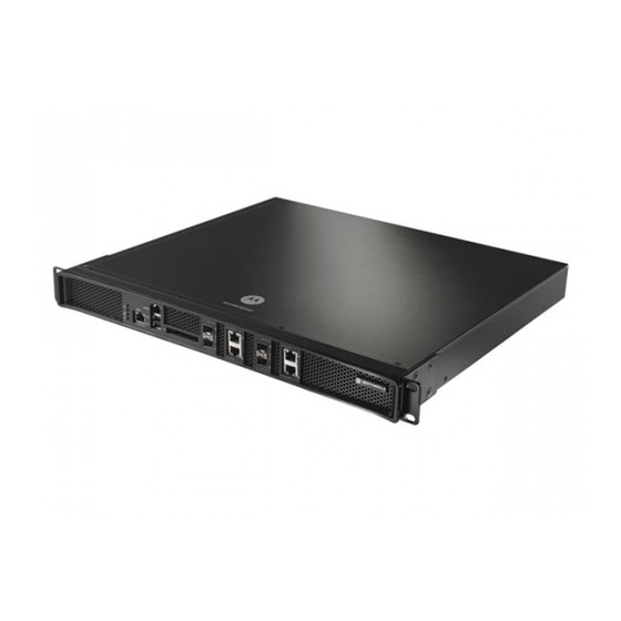
Motorola RFS7000 Series Installation Manual
Rf switch
Hide thumbs
Also See for RFS7000 Series:
- Reference manual (732 pages) ,
- System reference manual (466 pages) ,
- Troubleshooting manual (60 pages)
Table of Contents
Advertisement
Quick Links
Advertisement
Table of Contents

Related Manuals for Motorola RFS7000 Series


Summary of Contents for Motorola RFS7000 Series
- Page 1 RFS7000 Series RF Switch Installation Guide...
- Page 2 MOTOROLA and the Stylized M Logo are registered in the US Patent & Trademark Office. Symbol is a registered trademark of Symbol Technologies, Inc. All other product or service names are the property of their respective owners. © Motorola, Inc. 2007. All rights reserved.
-
Page 3: Table Of Contents
Contents 1.0 Introduction ......... 1 2.0 Specifications . -
Page 4: Introduction
By replacing access points with simpler access ports (or “thin” access points), the RFS7000 Series RF Switch becomes a WLAN’s single point of contact, thus reducing wireless networking complexity by moving management out of the ceiling and into the wiring closet. -
Page 5: Site Preparation
Attach only approved power cords to the device. • Motorola strongly recommends the use of an Uninterruptible Power Supply (UPS) that supports the RFS7000 Series • RF Switch power rating. Not using a UPS can result in data loss or equipment damage due to a power surge or power failure. -
Page 6: Specifications
• Install surge protection. Be sure to use a surge protection device between the electricity source and the RFS7000 Series RF Switch. • Install an Uninterruptible Power Supply (UPS). A UPS provides continuous power during a power outage. -
Page 7: Led Codes
RFS7000 Series RF Switch: Installation Guide LED Codes The RFS7010 RF Switch has four vertically-stacked LEDs on its front panel. Each of the switch’s Gigabit Ethernet ports have two status LEDs. These LEDs display two colors (green & amber), and three lit states (solid, blinking, and off). - Page 8 LED Codes 3.1.2 Switch Status (Primary System) System Status 1 LED System Status 2 LED Event Power off Green Solid No Redundancy Feature Enabled Redundancy Feature Enabled Green Solid Green Solid Actively Adopting Access Ports No License to adopt Access Ports or No Country Green Solid Amber Blinking Code configured on the switch.
-
Page 9: Temperature Status Led
RFS7000 Series RF Switch: Installation Guide 3.1.5 Temperature Status LED Temperature LED Event System Off Ambient Inlet Temperature is within specified Green Solid operating limit Ambient Inlet Temperature is near the maximum operating temperature Amber Solid During switch start up this LED will be lit Solid Amber. - Page 10 LED Codes 3.2 RJ-45 Gigabit Ethernet LEDs 3.2.1 RJ-45 Port Speed LED Port Speed LED Event 10 Mbps Green Solid 100 Mbps Green Blinking 1000 Mbps Amber Blinking Port Fault 3.2.2 RJ-45 Port Status LED Port Status LED Event No Link or Administratively shut down Green Solid Link present Green Blinking...
-
Page 11: Sfp Gigabit Ethernet Leds
RFS7000 Series RF Switch: Installation Guide 3.3 SFP Gigabit Ethernet LEDs 3.3.1 SFP Port Speed LED Port Speed LED Event Green Blinking 1000 Mbps Amber Blinking Module or Tx/Rx Fault Loss 3.3.2 SFP Port Status LED Port Status LED Event... -
Page 12: Out Of Band Management Port Speed Led
LED Codes 3.4 Out of Band Management Port LEDs 3.4.1 Out of Band Management Port Speed LED Port Speed LED Event 10 Mbps Green Solid 100 Mbps Amber Blinking Port Fault 3.5 Out of Band Management Port Status LED Port Status LED Event No Link Green Solid... -
Page 13: Hardware Setup
Console connector. The above diagram shows each of those ports and the cables or devices attached to them. The sections that follow describe detailed connection and cabling information for each port. For software configuration, please see the RFS7000 Series RF Switch System Reference Guide available from the Motorola website. - Page 14 The RFS7010 RF Switch has four RJ-45 Gigabit Ethernet ports and four Gigabit SFP (fiber optic) ports. Using the RJ-45 ports requires connecting a Category-6 Ethernet cable to the port. To use the Gigabit SFP ports, first install the SFP Modules (Motorola Part Number: Fiber-3000-1S-WWR).
-
Page 15: Installing Gigabit Ethernet Sfps
RFS7000 Series RF Switch: Installation Guide 4.2.1 Installing Gigabit Ethernet SFPs Open the bail on the transceiver. Insert each of the SFP transceivers into the corresponding ports on the switch. - Page 16 Hardware Setup Once the SFP transceivers are properly seated in their ports, close the bails to lock the transceivers in place. Insert the fiber optic cables into the installed transceivers.
-
Page 17: Connecting Usb Devices
If applicable, connect the USB cable to a USB storage device. If applicable, power on the USB storage device. Follow the instructions in the RFS7000 Series RF Switch System Reference for more information on accessing USB storage devices from the switch. -
Page 18: Installing A Compact Flash Card
Hardware Setup 4.4 Installing a Compact Flash Card The RFS7010 RF Switch contains a Compact Flash slot for firmware updates and use by Motorola service technicians. Follow the setup instructions below to connect a Compact Flash Card to the switch and then access that card through the Web UI. -
Page 19: Rack Mount Instructions
RFS7000 Series RF Switch: Installation Guide 4.5 Rack Mount Instructions To install the RFS7000 Series RF Switch in a rack: The rack mounting brackets are installed at the factory. No additional steps are needed. Attach the brackets to the rack using screws appropriate for your rack’s mounting holes. - Page 20 Hardware Setup 4.6 RFS7000 Series RF Switch Console Port Setup To add the RFS7000 Series RF Switch to the network and prepare it for initial configuration: Using the supplied console cable (pictured below), connect the RFS7000 Series RF Switch serial port to an RS-232 (DB-9) serial port on a separate computer (the “configuration computer”).
- Page 21 RFS7000 Series RF Switch: Installation Guide 4.7 Supplying Power to the RFS7000 Series RF Switch Plug an approved AC power cord into the power connector at the back of the RFS7000 Series RF Switch. Plug the cord into a standard AC outlet with a voltage range of 100 to 240 VAC.
-
Page 22: Verifying The Installation
• After the software has finished initializing, the System 1 LED will be lit solid green and the bottom System 2 LED will be off. The RFS7000 Series RF Switch is ready to be configured, as described in the RFS7000 Series RF Switch System Reference. -
Page 23: Regulatory Information
Numbers, Support, and Sales. All Motorola devices are designed to be compliant with rules and regulations in locations they are sold and will be labeled as required. Any changes or modifications to Motorola equipment, not expressly approved by Motorola, could void the user’s authority to operate the equipment. -
Page 24: Statement Of Compliance
Cet appareil numérique de la classe A est conforme à la norme NMB-003 du Canada. Marking and European Economic Area (EEA) Statement of Compliance Motorola, Inc., hereby declares that this device is in compliance with all the applicable Directives, 89/336/EEC, 73/23/EEC. A Declaration of Conformity may be obtained from http://www2.symbol.com/doc/... - Page 25 RFS7000 Series RF Switch: Installation Guide Italiano: per i clienti dell'UE: tutti i prodotti che sono giunti al termine del rispettivo ciclo di vita devono essere restituiti a Symbol al fine di consentirne il riciclaggio. Per informazioni sulle modalità di restituzione, visitare il seguente sito Web: http://www.symbol.com/ environmental_compliance.
-
Page 26: Part Numbers, Support, And Sales
• Model number or product name • Software type and version number Motorola responds to calls by email, telephone or fax within the time limits set forth in support agreements. If you purchased your Enterprise Mobility business product from a Motorola business partner, contact that business partner for support. - Page 27 RFS7000 Series RF Switch: Installation Guide General Information Obtain additional information by contacting Motorola at: 1-800-722-6234, inside North America +1-516-738-5200, in/outside North America http://www.motorola.com/ Product Sales and Product Information North America International Motorola, Inc. Motorola, Inc. One Symbol Plaza Symbol Place...
-
Page 28: End-User License Agreement
ANOTHER PERSON OR ANY OTHER LEGAL ENTITY, YOU REPRESENT AND WARRANT THAT YOU HAVE THE AUTHORITY TO BIND THAT COMPANY, PERSON OR ENTITY. LICENSE GRANT. Subject to the terms of this Agreement, Motorola, Inc. and/or its subsidiaries ("Licensor") hereby grants Licensee a limited, personal, non-sublicensable, non-transferable, nonexclusive license to use the software that Licensee is about to download or install and the documentation that accompanies it (collectively, the "Software") - Page 29 RFS7000 Series RF Switch: Installation Guide interrupt, destroy or limit the functionality of any computer software or hardware or telecommunications equipment. Licensee, not Licensor, remains solely responsible for all Content that Licensee uploads, posts, e-mails, transmits, or otherwise disseminates using, or in connection with, the Software.
- Page 30 "Restricted Rights" as provided for in FAR, 48 CFR 52.227-14 (JUNE 1987) or DFAR, 48 CFR 252.227- 7013 (OCT 1988), as applicable. The "Manufacturer" for purposes of these regulations is Motorola, Inc., One Symbol Plaza, Holtsville, NY 11742.
- Page 31 MOTOROLA INC. 1303 E. ALGONQUIN ROAD SCHAUMBURG, IL 60196 http://www.motorola.com 72E-85979-01 Revision A April 2007...