Table of Contents
Advertisement
Quick Links
Advertisement
Table of Contents

Related Manuals for Eaton 9130


Summary of Contents for Eaton 9130
- Page 1 ® Eaton 9130 UPS 700/3000 VA User's Guide...
- Page 2 Protection Association, Inc. Phillips and Pozidriv are registered trademarks of Phillips Screw Company. All other trademarks are property of their respective companies. Copyright 2011 Eaton Corporation, Raleigh, NC, USA. All rights reserved. No part of this document may be reproduced in any way without the express written approval of Eaton Corporation.
- Page 3 Class A EMC Statements FCC Part 15 This equipment has been tested and found to comply with the limits for a Class A digital device, pursuant to part 15 of the FCC Rules. These limits are designed to provide reasonable protection against harmful interference when the equipment is operated in a commercial environment.
-
Page 4: Special Symbols
Special Symbols The following are examples of symbols used on the UPS or accessories to alert you to important information: RISK OF ELECTRIC SHOCK - Observe the warning associated with the risk of electric shock symbol. CAUTION: REFER TO OPERATOR'S MANUAL - Refer to your operator's manual for additional information, such as important operating and maintenance instructions. -
Page 5: Table Of Contents
Configuring Automatic Restart ..........Eaton 9130 700/3000 VA UPS User’s Guide 164201718—Rev 7 www.eaton.com/powerquality... - Page 6 WARRANTY................Eaton 9130 700/3000 VA UPS User’s Guide 164201718—Rev 7 www.eaton.com/powerquality...
-
Page 7: Introduction
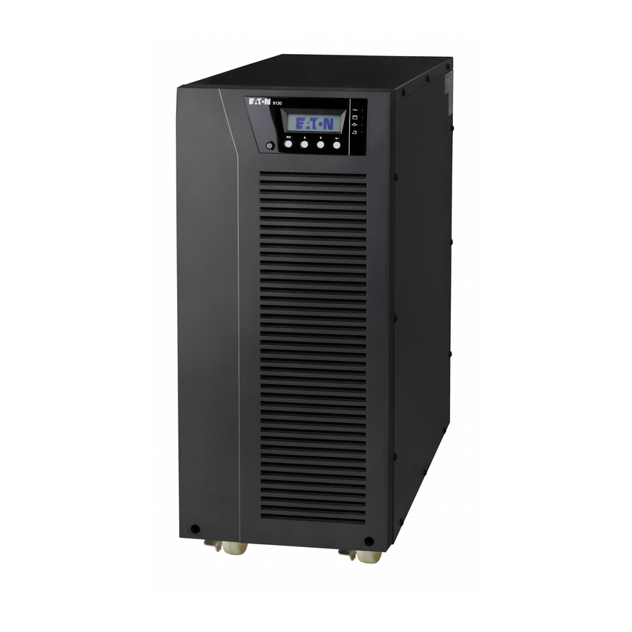
– causing hours of lost productivity and expensive repairs. With the Eaton 9130, you can safely eliminate the effects of power disturbances and guard the integrity of your equipment. Providing outstanding performance and reliability, the Eaton 9130's unique benefits include: True online double-conversion technology with high power density, utility frequency independence, and generator compatibility. - Page 8 Introduction Figure 3 shows the Eaton 9130 tower UPS and optional EBM. Figure 3. The Eaton 9130 Tower UPS and EBM (2000/3000 VA Models Shown) Eaton 9130 700/3000 VA UPS User’s Guide 164201718—Rev 7 www.eaton.com/powerquality...
-
Page 9: Safety Warnings
Keep unauthorized personnel away from batteries. Proper disposal of batteries is required. Refer to your local codes for disposal requirements. Never dispose of batteries in a fire. Batteries may explode when exposed to flame. Eaton 9130 700/3000 VA UPS User’s Guide 164201718—Rev 7 www.eaton.com/powerquality... - Page 10 Älä päästä valtuuttamatonta henkilöstöä lähelle akkuja. Akusto täytyy hävittää säädösten mukaisella tavalla. Noudata paikallisia määräyksiä. Älä koskaan heitä akkuja tuleen. Ne voivat räjähtää. Eaton 9130 700/3000 VA UPS User’s Guide 164201718—Rev 7 www.eaton.com/powerquality...
- Page 11 Une mise au rebut réglementaire des batteries est obligatoire. Consulter les règlements en vigueur dans votre localité. Ne jamais jeter les batteries au feu. L'exposition aux flammes risque de les faire exploser. Eaton 9130 700/3000 VA UPS User’s Guide 164201718—Rev 7 www.eaton.com/powerquality...
- Page 12 Trennen Sie anschließend den Anschluss der internen USV-Batterie (siehe Abbildung 24 auf Seite 47 für im Rack montierte Modelle oder Abbildung 26 auf Seite 49 für Tower-Modelle). Eaton 9130 700/3000 VA UPS User’s Guide 164201718—Rev 7 www.eaton.com/powerquality...
- Page 13 (vedere Figura 24 a pagina 45 per i modelli per rack o Figura 26 a pagina 48 per i modelli tower) Eaton 9130 700/3000 VA UPS User’s Guide 164201718—Rev 7 www.eaton.com/powerquality...
- Page 14 прочтите все инструкции. Сохраните данное руководство для дальнейшего использования. ОПАСНО В данном ИБП имеются СМЕРТЕЛЬНО ОПАСНЫЕ НАПРЯЖЕНИЯ. Все работы по ремонту и обслуживанию должны выполняться ТОЛЬКО УПОЛНОМОЧЕННЫМ ОБСЛУЖИВАЮЩИМ ПЕРСОНАЛОМ. Внутри ИБП нет узлов, ОБСЛУЖИВАЕМЫХ ПОЛЬЗОВАТЕЛЕМ. Eaton 9130 700/3000 VA UPS User’s Guide 164201718—Rev 7 www.eaton.com/powerquality...
- Page 15 Este manual contiene instrucciones importantes que debe seguir durante la instalación y el mantenimiento del SIE y de las baterías. Por favor, lea todas las instrucciones antes de poner en funcionamiento el equipo y guarde este manual para referencia en el futuro. Eaton 9130 700/3000 VA UPS User’s Guide 164201718—Rev 7 www.eaton.com/powerquality...
- Page 16 Es necesario desechar las baterías de un modo adecuado. Consulte las normas locales para conocer los requisitos pertinentes. Nunca deseche las baterías en el fuego. Las baterías pueden explotar si se las expone a la llama. Eaton 9130 700/3000 VA UPS User’s Guide 164201718—Rev 7 www.eaton.com/powerquality...
- Page 17 Håll ej behörig personal borta från batterierna. Batterierna måste avyttras enligt anvisningarna i lokal lagstiftning. Använda batterier får aldrig brännas upp. De kan explodera. Eaton 9130 700/3000 VA UPS User’s Guide 164201718—Rev 7 www.eaton.com/powerquality...
-
Page 18: Installation
Discard or recycle the packaging in a responsible manner, or store it for future use. Place the cabinet in a protected area that has adequate airflow and is free of humidity, flammable gas, and corrosion. Eaton 9130 700/3000 VA UPS User’s Guide 164201718—Rev 7 www.eaton.com/powerquality... -
Page 19: Checking The Accessory Kit
Use the UPS user's guide to install both the UPS and the EBM. Rackmount Installation The Eaton 9130 rackmount cabinet comes with all of the hardware required for installation in a standard 19-inch rack or JIS seismic rackmount configuration with square and round mounting holes. The rail assemblies adjust to mount in Standard 19-inch racks with front to rear rail distances from 61–76 cm... -
Page 20: Tools Required
Secure one rail assembly to the front of the rack with one M6x16 pan-head screw and one M6 cage nut. Using two M6 cage nuts and two M6x16 pan-head screws, attach the rail assembly to the rear of the rack. Eaton 9130 700/3000 VA UPS User’s Guide 164201718—Rev 7 www.eaton.com/powerquality... - Page 21 (see Figure 7). Install the bottom screw on each side through the bottom hole of the mounting bracket and the bottom hole of the rail. Repeat for any optional cabinets. Eaton 9130 700/3000 VA UPS User’s Guide 164201718—Rev 7 www.eaton.com/powerquality...
-
Page 22: Rackmount Wiring Installation
To remove the cover, remove and retain the two screws on the right side of the cover. Grasp the top and bottom of the cover and slide the cover to the right. Eaton 9130 700/3000 VA UPS User’s Guide 164201718—Rev 7 www.eaton.com/powerquality... - Page 23 2000–3000 VA models. Connect red to red, and black to black. Press the two parts tightly together to ensure a proper connection. – 0 Figure 10. Connecting the UPS Internal Batteries Eaton 9130 700/3000 VA UPS User’s Guide 164201718—Rev 7 www.eaton.com/powerquality...
-
Page 24: Connecting The Ebm(S)
To remove the cover, remove and retain the two screws on the right side of the cover. Grasp the sides of the cover and slide the cover to the left and then away from the cabinet. Eaton 9130 700/3000 VA UPS User’s Guide 164201718—Rev 7 www.eaton.com/powerquality... - Page 25 All models. To connect a second EBM, unclip the EBM connector on the first EBM and pull gently to extend the wiring to the EBM connector on the second EBM. Repeat for any additional EBMs. Eaton 9130 700/3000 VA UPS User’s Guide 164201718—Rev 7 www.eaton.com/powerquality...
-
Page 26: Tower Installation
Return to Step 4 on page 18 to continue the UPS installation. Tower Installation The Eaton 9130 tower cabinet comes fully assembled and ready to connect. CAUTION The cabinet is heavy (see page 56). Removing the cabinet from its carton requires a minimum of two people. -
Page 27: Installing The Ups
Connect the internal battery connector (see Figure 15). Connect the white connectors together, connecting red to red, and black to black. Press the two parts tightly together to ensure a proper connection. Eaton 9130 700/3000 VA UPS User’s Guide 164201718—Rev 7 www.eaton.com/powerquality... -
Page 28: Connecting The Ebm(S)
A small amount of arcing may occur when connecting an EBM to the UPS. This is normal and will not harm personnel. Insert the EBM cable into the UPS battery connector quickly and firmly. Eaton 9130 700/3000 VA UPS User’s Guide 164201718—Rev 7 www.eaton.com/powerquality... - Page 29 Continue to “UPS Initial Startup” on page 24. Remove cable retention clip. Plug in EBM cable. Rotate clip. Reinstall cable retention clip. 1000–1500 VA Models 2000–3000 VA Models Figure 16. Connecting the EBMs Eaton 9130 700/3000 VA UPS User’s Guide 164201718—Rev 7 www.eaton.com/powerquality...
-
Page 30: Ups Initial Startup
At initial startup, the UPS sets system frequency according to input line frequency (input frequency auto-sensing is enabled by default). After initial startup, auto-sensing is disabled until manually re-enabled by output frequency setting. Eaton 9130 700/3000 VA UPS User’s Guide 164201718—Rev 7 www.eaton.com/powerquality... - Page 31 Deactivate the external REPO switch and restart the UPS. NOTE The internal batteries charge to 90% capacity in less than 3 hours. However, Eaton recommends that the batteries charge for 48 hours after installation or long-term storage. If optional EBMs are installed, see the recharge times listed in Table 30 on page 68.
-
Page 32: Operation
Chapter 4 Operation This chapter contains information on how to use the Eaton 9130, including front panel operation, operating modes, UPS startup and shutdown, transferring the UPS between modes, retrieving the Event Log, setting the power strategy, and configuring bypass settings, load segments, and battery settings. -
Page 33: Changing The Language
"REPO terminal setting "Serial number "Part number Identification UPS Type / Part Number / Serial Number / Firmware Settings User Settings See Table 3 for details. Service Settings This menu is password-protected. Eaton 9130 700/3000 VA UPS User’s Guide 164201718—Rev 7 www.eaton.com/powerquality... -
Page 34: User Settings
NOTE * See “Configuring Bypass Settings”on page 34. NOTE ** The cXSlot Signal setting is for a communication card. The cXSlot Serial setting is for the relay card. Eaton 9130 700/3000 VA UPS User’s Guide 164201718—Rev 7 www.eaton.com/powerquality... - Page 35 [Enabled] [Disabled] Enabled NOTE * See “Configuring Bypass Settings”on page 34. NOTE ** The cXSlot Signal setting is for a communication card. The cXSlot Serial setting is for the relay card. Eaton 9130 700/3000 VA UPS User’s Guide 164201718—Rev 7 www.eaton.com/powerquality...
- Page 36 See “Logic Power Off” on page 33. NOTE * See “Configuring Bypass Settings”on page 34. NOTE ** The cXSlot Signal setting is for a communication card. The cXSlot Serial setting is for the relay card. Eaton 9130 700/3000 VA UPS User’s Guide 164201718—Rev 7 www.eaton.com/powerquality...
-
Page 37: Operating Modes
Operation Operating Modes The Eaton 9130 front panel indicates the UPS status through the UPS indicators (see Figure 17 on page 26). Normal Mode During Normal mode, the indicator illuminates solid and the UPS is powered from the utility. The UPS monitors and charges the batteries as needed and provides filtered power protection to your equipment. -
Page 38: Standby Mode
Before using this feature, the UPS must have been powered by utility power with output enabled at least once. NOTE 2 Battery start can be disabled. See the “Start on Battery” setting in “User Settings” on page 28. Eaton 9130 700/3000 VA UPS User’s Guide 164201718—Rev 7 www.eaton.com/powerquality... -
Page 39: Ups Shutdown
The equipment does not restart automatically when normal utility power is restored if the unit is shut down by power shutdown management software or a connectivity card, such as the Intelligent Power Protector (IPP) or a Network Card-MS. ® Eaton 9130 700/3000 VA UPS User’s Guide 164201718—Rev 7 www.eaton.com/powerquality... -
Page 40: Setting Power Strategy
Bypass voltage is between the “Bypass Voltage Low Limit” and “Bypass Voltage High Limit” settings. Bypass frequency is within nominal frequency 5 Hz. The inverter is synchronized with Bypass when the “Unsynchronized Transfers” setting is disabled. Eaton 9130 700/3000 VA UPS User’s Guide 164201718—Rev 7 www.eaton.com/powerquality... -
Page 41: Configuring Load Segments
See “Rear Panels” on page 69 for load segments for each UPS model. To control the load segments with power management software, see your power management software manual for details (refer to the Software Suite CD or www.eaton.com/powerquality for the latest information). To control the load segments through the display: Press any button to activate the menu options, then select CONTROL and LOAD SEGMENTS. -
Page 42: Configuring Battery Settings
The UPS must be in Normal mode, with no active alarms. The batteries must be fully charged. The bypass voltage must be acceptable. No manual battery test was initiated previously in the same charging cycle. Eaton 9130 700/3000 VA UPS User’s Guide 164201718—Rev 7 www.eaton.com/powerquality... -
Page 43: Configuring Automatic Restart
You can set the load segment for the amount of time to delay the restart once utility returns, using the “Automatic Start Delay” setting. You can also configure UPS restart to depend on the battery charge level, using the “Battery Charge % to Restart” setting. Eaton 9130 700/3000 VA UPS User’s Guide 164201718—Rev 7 www.eaton.com/powerquality... -
Page 44: Communication
Continue to “Operation” on page 26 to start up the UPS. Communication Options The Eaton 9130 has serial communication capabilities through the USB and RS-232 communication ports or through a connectivity card in the available communication bay. The UPS supports two serial communication devices according to Table 5: Table 5. -
Page 45: Rs-232 And Usb Communication Ports
Connectivity Cards Connectivity cards allow the UPS to communicate in a variety of networking environments and with different types of devices. The Eaton 9130 has one available communication bay for the following connectivity cards (see Figure 20): Network Card-MS (replaces 103006826 and 66102) has SNMP and HTTP capabilities as well as monitoring through a Web browser interface;... -
Page 46: Remote Emergency Power-Off
HD-384-48 S1, “Electrical Installation of the Buildings, Part 4: Protection for Safety, Chapter 46: Isolation and Switching. ” NOTE Leave the REPO connector installed in the REPO port on the UPS even if the REPO function is not needed. Eaton 9130 700/3000 VA UPS User’s Guide 164201718—Rev 7 www.eaton.com/powerquality... -
Page 47: Forced To Bypass State
The relay output contacts must not be connected to any utility connected circuits. Reinforced insulation to the utility is required. The relay output contacts have a maximum rating of 30 Vac/1A and 60 Vdc/2A nominal values. Eaton 9130 700/3000 VA UPS User’s Guide 164201718—Rev 7 www.eaton.com/powerquality... -
Page 48: Programmable Signal Inputs
If active, the UPS generates the “Building Alarm 1”alarm. Table 10. Polarity Options Input Description High Active state on high voltage (+Udc) level Active state on low voltage (GND or -Udc) level Eaton 9130 700/3000 VA UPS User’s Guide 164201718—Rev 7 www.eaton.com/powerquality... -
Page 49: Power Management And Protection Software
Eaton provides several comprehensive power monitoring/management software products and UPS load protection software products. Your UPS ships with a CD containing several of the software products. Visit www.eaton.com/pq/software for the latest updates to the products on your CD, as well as any new power monitoring/management and protection software products. -
Page 50: Maintenance
If you store the UPS for a long period, recharge the battery every six months by connecting the UPS to utility power. The internal batteries charge to 90% capacity in less than three hours. However, Eaton recommends that the batteries charge for 48 hours after long-term storage. If optional EBMs are installed, see the recharge times listed in Table 30 on page 68. -
Page 51: Replacing Rackmount Ups Internal Batteries
NOTE A ribbon cable connects the LCD control panel to the UPS. Do not pull on the cable or disconnect it. Eaton 9130 700/3000 VA UPS User’s Guide 164201718—Rev 7 www.eaton.com/powerquality... - Page 52 Slide the new battery package into the cabinet. Push the battery package in firmly. Replace the battery cover plate onto the screw mounts, threading the battery connector through the access slot. Eaton 9130 700/3000 VA UPS User’s Guide 164201718—Rev 7 www.eaton.com/powerquality...
-
Page 53: Replacing Tower Ups Internal Batteries
To remove the cover, push down on the top of the cover and pull the cover toward you to unclip it from the cabinet. NOTE A ribbon cable connects the LCD control panel to the UPS. Do not pull on the cable or disconnect it. Eaton 9130 700/3000 VA UPS User’s Guide 164201718—Rev 7 www.eaton.com/powerquality... - Page 54 Carefully pull the handle on the battery tray and slide the battery package slowly out onto a flat, stable surface; use two hands to support the battery package. See “Recycling the Used Battery or UPS” on page 52 for proper disposal. Eaton 9130 700/3000 VA UPS User’s Guide 164201718—Rev 7 www.eaton.com/powerquality...
- Page 55 To replace the cover, verify that the ribbon cable is protected, then insert the clips on the back of the cover into the cabinet and push firmly to snap the cover into place. 10. Continue to “Testing New Batteries” on page 52. Eaton 9130 700/3000 VA UPS User’s Guide 164201718—Rev 7 www.eaton.com/powerquality...
-
Page 56: Replacing Rackmount Ebms
If you are installing more than one new EBM, for each additional EBM remove the EBM cable knockout on the top and bottom of the EBM front cover. See Figure 27 for the location of the EBM cable knockouts. Eaton 9130 700/3000 VA UPS User’s Guide 164201718—Rev 7 www.eaton.com/powerquality... -
Page 57: Replacing Tower Ebms
For each cable retention clip removed, rotate the clip and install it under each EBM cable connection using the retained screws. Verify that the EBM connections are tight and that adequate bend radius and strain relief exist for each cable. Eaton 9130 700/3000 VA UPS User’s Guide 164201718—Rev 7 www.eaton.com/powerquality... -
Page 58: Testing New Batteries
Updating the UPS Firmware To keep the UPS firmware updated with the latest improvements and benefits, please contact your regional service team. Eaton 9130 700/3000 VA UPS User’s Guide 164201718—Rev 7 www.eaton.com/powerquality... -
Page 59: Specifications
Chapter 7 Specifications This chapter provides specifications for the Eaton 9130 UPS models: Communication options Model lists Weights and dimensions Electrical input and output Environmental and safety Battery Table 11. Communication Options (All Models) Communication Bay (1) available independent communication bay for connectivity cards... - Page 60 PW9130G3000T-XLEU 3000 VA / 2700W Figure 55 on page 80 PW9130G700T-XLAU 700 VA / 630W Figure 57 on page 81 PW9130G1000T-XLAU 1000 VA / 900W Figure 56 on page 80 Eaton 9130 700/3000 VA UPS User’s Guide 164201718—Rev 7 www.eaton.com/powerquality...
- Page 61 86.5 x 438 x 430 mm 28.1 kg (62.0 lb) (3.4" x 17.2" x 16.9") PW9130N1500R-EBM2US PW9130N3000R-EBM2U 86.5 x 438 x 600 mm 41.0 kg (90.6 lb) (3.4" x 17.2" x 23.6") PW9130N3000R-EBM2US Eaton 9130 700/3000 VA UPS User’s Guide 164201718—Rev 7 www.eaton.com/powerquality...
- Page 62 50/60 Hz auto-sensing Frequency Range 4070 Hz before transfer to battery Bypass Voltage Range +10/-15% of nominal (default) Noise Filtering Metal oxide varistors (MOVs) for normal and common mode noise Eaton 9130 700/3000 VA UPS User’s Guide 164201718—Rev 7 www.eaton.com/powerquality...
- Page 63 120V / 16.7A 100*, 110**, 120, 127 90–138 Vac PW9130L3000T-XL 120V / 25.0A 100*, 110**, 120, 127 90–138 Vac PW9130G1000T-XL 208V / 4.4A 200*, 208**, 220, 230, 240 160–276 Vac Eaton 9130 700/3000 VA UPS User’s Guide 164201718—Rev 7 www.eaton.com/powerquality...
- Page 64 IEC C14-10A Schuko 10A to IEC 320-10A PW9130i2000R-XL2U IEC C14-10A Schuko 10A to IEC 320-10A PW9130i3000R-XL2U IEC C20-16A Schuko 16A to IEC 320-16A PW9130i3000R-XL2US IEC C20-16A Schuko 16A to IEC 320-16A Eaton 9130 700/3000 VA UPS User’s Guide 164201718—Rev 7 www.eaton.com/powerquality...
- Page 65 >93% High Efficiency mode for Low Voltage Models Sync with line 3 Hz of nominal line 0.1 Hz of auto-selected nominal frequency Frequency Regulation frequency (outside this range: 0.1 Hz of auto-selected nominal frequency) Eaton 9130 700/3000 VA UPS User’s Guide 164201718—Rev 7 www.eaton.com/powerquality...
- Page 66 (2) 20A AC breakers PW9130L3000R-XL2U (1) L5-30R, (6) 5-20T, None (2) 20A AC breakers PW9130L3000R-XL2US (1) L5-30R, (6) 5-20T, None (2) 20A AC breakers PW9130G1000R-XL2U (1) L6-20, (2) 6-20R None Eaton 9130 700/3000 VA UPS User’s Guide 164201718—Rev 7 www.eaton.com/powerquality...
- Page 67 (6) IEC 320-10A None PW9130G2000T-XLEU (8) IEC 320-10A, (1) IEC 320-16A None PW9130G3000T-XLEU (8) IEC 320-10A, (1) IEC 320-16A None PW9130G700T-XLAU (4) Aust 10A None PW9130G1000T-XLAU (4) Aust 10A None Eaton 9130 700/3000 VA UPS User’s Guide 164201718—Rev 7 www.eaton.com/powerquality...
- Page 68 Table 26. Battery Runtimes (in Minutes) at 100% Load (Rack Models) PF0.9 Rack Models Load (VA/Watts) Internal Batteries + 1 EBM + 2 EBMs + 3 EBMs + 4 EBMs PW9130L700R-XL2U / PW9130L700R-XL2US 700/630 525/473 Eaton 9130 700/3000 VA UPS User’s Guide 164201718—Rev 7 www.eaton.com/powerquality...
- Page 69 1500/1350 1125/1013 750/675 375/338 PW9130L2000R-XL2U / PW9130L2000R-XL2US 2000/1800 1500/1350 1000/900 500/450 PW9130G2000R-XL2U PW9130G2000R-XL2UEU / PW9130i2000R-XL2U 2000/1800 1500/1350 1000/900 500/450 PW9130L2500R-XL2U 2500/2250 1875/1688 1250/1125 625/563 PW9130G2500R-XL2U / PW9130G2500R-XL2UEU 2500/2250 1875/1688 1250/1125 Eaton 9130 700/3000 VA UPS User’s Guide 164201718—Rev 7 www.eaton.com/powerquality...
- Page 70 PW9130L700T-XL 700/630 525/473 350/315 175/158 PW9130i700T 700/630 525/473 350/315 175/158 PW9130L1000T-XL 1000/900 750/675 500/450 250/225 PW9130G1000T-XL / PW9130G1000T-XLEU / PW9130i1000T-XL 1000/900 750/675 500/450 250/225 PW9130L1500T-XL 1500/1350 1125/1013 750/675 375/338 PW9130i1500T-XL Eaton 9130 700/3000 VA UPS User’s Guide 164201718—Rev 7 www.eaton.com/powerquality...
- Page 71 + 2 EBMs + 3 EBMs + 4 EBMs PW9130L700R-XL2U / PW9130L700R-XL2US (Estimated runtimes) 700/490 525/368 350/245 175/123 PW9130L1000R-XL2U 1000/700 750/525 500/350 250/175 PW9130G1000R-XL2U / PW9130G1000R-XL2UEU / PW9130i1000R-XL2U / PW9130i1000R-XL2US 1000/700 Eaton 9130 700/3000 VA UPS User’s Guide 164201718—Rev 7 www.eaton.com/powerquality...
- Page 72 PW9130L2500R-XL2U (Estimated runtimes) 2500/2250 1875/1688 1250/1125 625/563 PW9130G2500R-XL2U / PW9130G2500R-XL2UEU (Estimated runtimes) 2500/2250 1875/1688 1250/1125 625/563 PW9130L3000R-XL2U / PW9130L3000R-XL2US 3000/2100 2250/1575 1500/1050 750/525 PW9130G3000R-XL2U / PW9130G3000R-XL2UEU / PW9130i3000R-XL2U / PW9130i3000R-XL2US 3000/2100 2250/1575 Eaton 9130 700/3000 VA UPS User’s Guide 164201718—Rev 7 www.eaton.com/powerquality...
- Page 73 PW9130L1000T-XL 1000/700 750/525 500/350 250/175 PW9130G1000T-XL / PW9130G1000T-XLEU / PW9130i1000T-XL 1000/700 750/525 500/350 250/175 PW9130L1500T-XL 1500/1050 1125/788 750/525 375/263 PW9130i1500T-XL 1500/1050 1125/788 750/525 375/263 PW9130L2000T-XL (Estimated runtimes) 2000/1400 1500/1050 1000/700 Eaton 9130 700/3000 VA UPS User’s Guide 164201718—Rev 7 www.eaton.com/powerquality...
- Page 74 Recharge Time (to 90%) 1 EBM: 9 hours; 2 EBMs: 15 hours; 3 EBMs: 21 hours; 4 EBMs: 27 hours Battery Port External three-pole Anderson connector on UPS for connection to EBM Eaton 9130 700/3000 VA UPS User’s Guide 164201718—Rev 7 www.eaton.com/powerquality...
-
Page 75: Rear Panels
Port Input Connector Figure 29. Model PW9130G1000R-XL2U REPO Communication Port Port (6) IEC 320-10A Relay RS-232 IEC C14-10A Output Receptables Port Port Input Connector Figure 30. Models PW9130i1000R-XL2U, PW9130i1000R-XL2US, PW9130G1000R-XL2UEU Eaton 9130 700/3000 VA UPS User’s Guide 164201718—Rev 7 www.eaton.com/powerquality... - Page 76 Output Receptables Port Input Connector Port Figure 32. Model PW9130G1500R-XL2UAU (6) 15-5R REPO Communication Output Receptables Port Port Relay RS-232 5-15P Port Port Input Cord Figure 33. Model PW9130L1500R-XL2U, PW9130L1500R-XL2US Eaton 9130 700/3000 VA UPS User’s Guide 164201718—Rev 7 www.eaton.com/powerquality...
- Page 77 Port Figure 35. Model PW9130L2000R-XL2U, PW9130L2000R-XL2US IEC C14-10A (4) 6-20R REPO RS-232 Communication Input Connector Output Receptables Port Port (1) L6-20 Relay Output Receptable Port Port Figure 36. Model PW9130G2000R-XL2U Eaton 9130 700/3000 VA UPS User’s Guide 164201718—Rev 7 www.eaton.com/powerquality...
- Page 78 Figure 38. Model PW9130G2000R-XL2UAU (6) 5-20T (2) 20A REPO RS-232 Communication Output Receptables AC Breakers Port Port (1) L5-30R Relay Output Receptable Port Port L5-30P Input Cord Figure 39. Models PW9130L2500R-XL2U, PW9130L3000R-XL2U, PW9130L3000R-XL2US Eaton 9130 700/3000 VA UPS User’s Guide 164201718—Rev 7 www.eaton.com/powerquality...
- Page 79 Figure 41. Models PW9130G2500R-XL2UEU, PW9130i3000R-XL2U, PW9130i3000R-XL2US PW9130G3000R-XL2UEU RS-232 IEC C20-16A (4) C13 REPO Communication Port Input Connector Output Receptables Port (1) C19 (3) Aust 10A Relay Output Receptable Output Receptables Port Port Figure 42. Model PW9130G3000R-XL2UAU Eaton 9130 700/3000 VA UPS User’s Guide 164201718—Rev 7 www.eaton.com/powerquality...
- Page 80 (6) 5-15R 5-15P Output Receptables Input Cord Figure 43. Model PW9130L700T-XL Communication RS-232 Port Relay Port Port Connection REPO Port (6) 5-15R 5-15P Output Receptables Input Cord Figure 44. Model PW9130L1500T-XL Eaton 9130 700/3000 VA UPS User’s Guide 164201718—Rev 7 www.eaton.com/powerquality...
- Page 81 Input Cord Figure 45. Model PW9130L1000T-XL RS-232 Relay Communication Port Port Port REPO Port Connection (1) L5-20R Output Receptable 5-20P Input Cord (4) 5-20T Output Receptables Figure 46. Model PW9130L2000T-XL Eaton 9130 700/3000 VA UPS User’s Guide 164201718—Rev 7 www.eaton.com/powerquality...
- Page 82 Output Receptables Figure 47. Model PW9130L3000T-XL Communication RS-232 Port Port Relay Port Connection REPO Port (2) 6-20R Output Receptables IEC C14-10A (1) L5-20R Input Connector Output Receptable Figure 48. Model PW9130G1000T-XL Eaton 9130 700/3000 VA UPS User’s Guide 164201718—Rev 7 www.eaton.com/powerquality...
- Page 83 Figure 49. Model PW9130G2000T-XL Communication REPO Relay RS-232 Port Port Port Port Connection (2) 6-20R Output Receptables (1) L6-20 Output Receptable (1) L6-30 Output Receptable IEC C20-16A Input Connector Figure 50. Model PW9130G3000T-XL Eaton 9130 700/3000 VA UPS User’s Guide 164201718—Rev 7 www.eaton.com/powerquality...
- Page 84 Input Connector Output Receptables Figure 51. Model PW9130i700T Communication RS-232 Port Relay Port Port Connection REPO Port (6) IEC 320-10A IEC C14-10A Input Connector Output Receptables Figure 52. Model PW9130i1500T-XL Eaton 9130 700/3000 VA UPS User’s Guide 164201718—Rev 7 www.eaton.com/powerquality...
- Page 85 Figure 53. Model PW9130G1000T-XLEU and PW9130i1000T-XL REPO RS-232 Relay Communication Port Port Port Port Connection (8) IEC 320-10A Output Receptables (1) IEC 320-16A IEC C14-10A Output Receptable Input Connector Figure 54. Models PW9130G2000T-XLEU and PW9130i2000T-XL Eaton 9130 700/3000 VA UPS User’s Guide 164201718—Rev 7 www.eaton.com/powerquality...
- Page 86 Output Receptable Input Connector Figure 55. Models PW9130G3000T-XLEU and PW9130i3000T-XL Communication Relay Port RS-232 Port Port REPO Port (4) Aust 10A IEC C14-10A Output Receptables Input Connector Figure 56. Model PW9130G1000T-XLAU Eaton 9130 700/3000 VA UPS User’s Guide 164201718—Rev 7 www.eaton.com/powerquality...
- Page 87 Output Receptables Input Connector Figure 57. Model PW9130G700T-XLAU Communication Connection Relay Port RS-232 Port Port REPO Port (4) Aust 10A IEC C14-10A Output Receptables Input Connector Figure 58. Model PW9130G1500T-XLAU Eaton 9130 700/3000 VA UPS User’s Guide 164201718—Rev 7 www.eaton.com/powerquality...
- Page 88 Figure 59. Model PW9130G2000T-XLAU REPO RS-232 Relay Communication Port Port Port Port Connection (5) Aust 10A Output Receptables (1) C13 Output Receptable IEC C20-16A Input Connector Figure 60. Model PW9130G3000T-XLAU Eaton 9130 700/3000 VA UPS User’s Guide 164201718—Rev 7 www.eaton.com/powerquality...
-
Page 89: Troubleshooting
Chapter 8 Troubleshooting The Eaton 9130 is designed for durable, automatic operation and also alerts you whenever potential operating problems may occur. Usually the alarms shown by the control panel do not mean that the output power is affected. Instead, they are preventive alarms intended to alert the user. - Page 90 The UPS does not provide the The batteries need charging or Apply utility power for 48 hours to charge the batteries. If expected backup time. service. the condition persists, contact your service representative. Eaton 9130 700/3000 VA UPS User’s Guide 164201718—Rev 7 www.eaton.com/powerquality...
-
Page 91: Silencing The Alarm
Please have the following information ready when you call for service: Model number Serial number Date of failure or problem Symptoms of failure or problem Customer return address and contact information Eaton 9130 700/3000 VA UPS User’s Guide 164201718—Rev 7 www.eaton.com/powerquality... - Page 92 A replacement or repair unit will be shipped, freight prepaid for all warrantied units. NOTE For critical applications, immediate replacement may be available. Call the Help Desk for the dealer or distributor nearest you. Eaton 9130 700/3000 VA UPS User’s Guide 164201718—Rev 7 www.eaton.com/powerquality...
-
Page 93: Warranty
LIMITED WARRANTY: This limited warranty (this “Warranty”) applies only to the original End-User (the “End-User”) of any Eaton 3105, 9120, 9125, 9135, 9140, and FERRUPS up to 3.1 kVA Products (individually and collectively, the “Product”) purchased on or after June 1, 2004 and cannot be transferred. This Warranty applies even in the event that the Product is initially sold by Company for resale to an End-User. - Page 94 Any costs for replacement equipment, installation, materials, freight charges, travel expenses or labor of Company representatives outside the terms of this Warranty will be borne by the End-User. Eaton 9130 700/3000 VA UPS User’s Guide 164201718—Rev 7 www.eaton.com/powerquality...
- Page 95 OBTAINING WARRANTY SERVICE: In the USA, call the Customer Reliability Center 7x24 at 800-356-5737 . Outside of the USA, call your local Eaton product sales or service representative, or call the Customer Reliability Center in the USA at 919-870-3149. For comments or questions about this Warranty, write to the Customer Quality Representative, 3301 Spring Forest Road, Raleigh, North Carolina 27616 USA.
- Page 96 TO MAKE A CLAIM: In the USA, call the Customer Reliability Center 7x24 at 800-356-5737 . Outside of the USA, contact your local Eaton product sales or service representative, or call the Customer Reliability Center in the USA at 919-870-3149. For comments or questions about this Load Protection Guaranty, write to the Customer Quality Representative, 3301 Spring Forest Road, Raleigh, North Carolina 27616 USA.
- Page 98 *P-164000042 1* 164201718 7...