Interlogix TruVision Installation Manual
Hide thumbs
Also See for TruVision:
- User manual (169 pages) ,
- Quick start manual (113 pages) ,
- Configuration manual (68 pages)

Related Manuals for Interlogix TruVision


Summary of Contents for Interlogix TruVision
- Page 1 TruVision IP Camera Installation Guide P/N 1072668A-EN • REV 1.0 • ISS 24SEP13 Downloaded from www.Manualslib.com manuals search engine...
- Page 2 Copyright © 2013 UTC Fire & Security Americas Corporation, Inc. Interlogix is part of UTC Climate Controls & Security, a unit of United Technologies Corporation. All rights reserved. Trademarks and The TruVision name and logo are trademarks of United patents Technologies.
- Page 3 For more information see: www.recyclethis.info. Contact information For contact information, see www.interlogix.com or www.utcfssecurityproducts.eu. Downloaded from www.Manualslib.com manuals search engine...
- Page 4 Downloaded from www.Manualslib.com manuals search engine...
-
Page 5: Table Of Contents
Mounting the VF dome camera 15 Mounting the indoor mini dome camera 19 Mounting the wedge dome camera 21 Using the camera with an Interlogix NVR or Hybrid DVR or another system 22 Using the camera with TruVision Navigator 22 ... -
Page 6: Introduction
Introduction Product overview This is the installation guide for TruVision IP camera models: TVB-1101 (1.3MPX IP bullet camera, PAL) TVB-3101 (1.3MPX IP bullet camera, NTSC) TVB-1102 (3MPX IP bullet camera, PAL) TVB-3102 (3MPX IP bullet camera, NTSC) ... -
Page 7: Installation
Installation This section provides information on how to install the cameras. Installation environment When installing your product, consider these factors: • Electrical: Install electrical wiring carefully. It should be done by qualified service personnel. Always use a proper PoE switch or a 12 VDC UL listed Class 2 or CE certified power supply to power the camera. -
Page 8: Package Contents
Hex wrench (for dome and mini dome cameras only) Installation manual CD with Configuration manual and TruVision Device Finder CAUTION: Use direct plug-in UL listed power supplies marked Class 2/CE certified or LPS (limited power source) of the required output rating as listed on the unit. -
Page 9: Camera Description
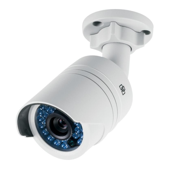
Table 1: Recommended power cable requirements Bullet camera: 12 VDC power jack or PoE (802.3af) Mini dome: PoE (802.3af) Wedge camera: 12 VDC power jack or PoE (802.3af) VF dome camera: 12 VDC power jack or PoE (802.3af) Camera description Figure 1: IP bullet camera Adjustable bracket... - Page 10 Figure 2: IP indoor mini dome camera Base Housing Lens Ethernet RJ45 and BNC cable Dome liner Safety cable Installation Guide Downloaded from www.Manualslib.com manuals search engine...
- Page 11 Figure 3: IP wedge camera Cover Base Lens Serial port SD card Reset button Ethernet RJ45 PoE port Converter pan Power supply Installation Guide Downloaded from www.Manualslib.com manuals search engine...
-
Page 12: Setting Up The Camera
Figure 4: IP VF dome camera Dome liner Mounting plate Housing Reset button Ethernet RJ45 PoE port Analog video output Power supply 10. Serial port Audio and alarm cables 11. SD card Lens Setting up the camera Note: If the light source where the camera is installed experiences rapid, wide- variations in lighting, the camera may not operate as intended. -
Page 13: Accessing The Sd Card
For further information, please refer to the “TruVision IP Camera Configuration Manual”. Program the camera to suit its location. For further information, please refer to the “TruVision IP Camera Configuration Manual”. Accessing the SD card Insert a Micro SD card with up to 64GB for local storage as a backup in case, for example, the network fails (see Figure 1 on page 9). - Page 14 Ceiling Mounting Hole Hole Hole Secure the mounting base to the ceiling or wall with the supplied screws. Loosen the adjustable nuts on the bracket, and adjust the camera from P/R/T (pan/rotate/tilt) direction. P Direction: 0 to 360°adjustable. T Direction: 0 to 90°adjustable. R Direction: 0 to 360°adjustable Adjust the lens to the required surveillance angle.
-
Page 15: Mounting The Vf Dome Camera
0° ~ 3 6 0° 0° ~ 3 6 0° 0°~ 9 0° Mounting the VF dome camera To mount the VF dome camera on a ceiling or wall: Loosen the three screws on the edge of the lower dome with screw driver. - Page 16 Drill the three screw holes on the ceiling with the supplied drill template. Cable hole Screw holes Installation Guide Downloaded from www.Manualslib.com manuals search engine...
- Page 17 If you want to route the cables inside the ceiling, drill a cable hole in the ceiling or wall using the drill template. Attach the camera to the ceiling or wall by aligning the housing holes with those in the ceiling. Secure the camera with the supplied screws as shown below.
- Page 18 panning position of the camera. Rotate the tilting axes to adjust the tilting position of the camera. Rotate the lens table to adjust the azimuth angle of the image. Zoom and focus adjustment. Loosen the zoom lever and move the lever between T(Tele) and W(Wide) to obtain the appropriate angle of view.
-
Page 19: Mounting The Indoor Mini Dome Camera
Mounting the indoor mini dome camera To mount the indoor mini dome camera on a ceiling: Drill the screw holes on the ceiling with the supplied drilling template. If you need to route the cables from the bottom of the camera, cut a cable hole in the ceiling. Using the supplied hex wrench, loosen the set screws to remove the dome enclosure. - Page 20 Note: If required, you can route cables through the side opening of the mounting base. Loosen the tilt lock screws, and adjust the tilting position in a range of 65 degrees. Retighten the tilt lock screws. Rotate the dome liner to adjust the panning position in a range of 360 degrees to obtain the desired surveillance angle.
-
Page 21: Mounting The Wedge Dome Camera
Reinstall the lower dome and tighten the screws. Mounting the wedge dome camera To mount the wedge dome camera on a ceiling: Drill the screw holes on the ceiling with the supplied drilling template. To route the cables from the base of the camera, cut a cable hole in the ceiling. -
Page 22: Using The Camera With An Interlogix Nvr Or Hybrid Dvr Or Another System
Using the camera with TruVision Navigator A camera must be connected to an Interlogix NVR or hybrid DVR in order to be operated by TruVision Navigator. Please refer to the TruVision Navigator user manual for instructions on operating the camera with the TruVision Navigator. -
Page 23: Specifications
-30 to 60 °C (-22 to 140°F) Dimensions Φ 60 × 153 mm (2.3” × 6.0”) Weight 373 g (0.82 lbs) Environmental rating IP66 TruVision IP indoor mini dome Electrical Voltage input PoE (IEEE 802.3af) Power consumption Max. 5 W Miscellaneous... -
Page 24: Truvision Ip Wedge Cameras
98 × 89 × 329 mm Dimensions (L × W × H) (3.86 ×3.49 × 12.94 in.) Weight 407 g (0.89 lb) Environmental rating IP66 TruVision IP VF mini dome cameras Electrical Voltage input 12 VDC, PoE (IEEE 802.3af) Power consumption Max. 5.5 W Miscellaneous... -
Page 25: Pin Definitions
Pin definitions There are eight wires on a standard UTP/STP cable and each wire is color-coded. The following shows the pin allocation and color of straight and crossover cable connection: Figure 3: Straight-through cable White/Orange White/Orange Orange Orange White-Green White-Green Blue Blue White/Blue... - Page 26 Please make sure your connected cables have the same pin assignment and color as above before deploying the cables in your network. Installation Guide Downloaded from www.Manualslib.com manuals search engine...
- Page 27 Downloaded from www.Manualslib.com manuals search engine...
- Page 28 Downloaded from www.Manualslib.com manuals search engine...