Advertisement
Safe Operation Practices • Set-Up • Operation • Maintenance • Service • Troubleshooting • Warranty
O
'
M
peratOr
s
anual
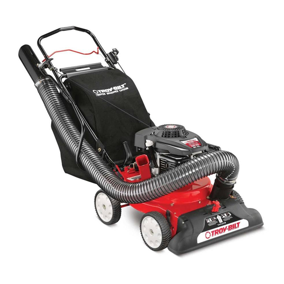
Self Propelled Yard Vacuum/Chipper/Shredder
with Vacuum/Hose — Model CSV 070
WARNING
READ AND FOLLOW ALL SAFETY RULES AND INSTRUCTIONS IN THIS MANUAL
BEFORE ATTEMPTING TO OPERATE THIS MACHINE.
FAILURE TO COMPLY WITH THESE INSTRUCTIONS MAY RESULT IN PERSONAL INJURY.
TROY-BILT LLC, P.O. BOX 361131 CLEVELAND, OHIO 44136-0019
Printed In USA
Form No. 769-09847
(May 1, 2014)
Advertisement
Table of Contents

Related Manuals for Troy-Bilt CSV 070


Summary of Contents for Troy-Bilt CSV 070
- Page 1 READ AND FOLLOW ALL SAFETY RULES AND INSTRUCTIONS IN THIS MANUAL BEFORE ATTEMPTING TO OPERATE THIS MACHINE. FAILURE TO COMPLY WITH THESE INSTRUCTIONS MAY RESULT IN PERSONAL INJURY. TROY-BILT LLC, P.O. BOX 361131 CLEVELAND, OHIO 44136-0019 Printed In USA Form No. 769-09847...
-
Page 2: Table Of Contents
Visit us on the web at www.troybilt.com See How-to Maintenance and Parts Installation Videos at www.troybilt.com/tutorials ◊ Call a Customer Support Representative at (800) 828-5500 or (330) 558-7220 ◊ Write to Troy-Bilt LLC • P.O. Box 361131 • Cleveland, OH • 44136-0019... -
Page 3: Safe Operation Practices
Important Safe Operation Practices WARNING: This symbol points out important safety instructions which, if not followed, could endanger the personal safety and/or property of yourself and others. Read and follow all instructions in this manual before attempting to operate this machine. Failure to comply with these instructions may result in personal injury. - Page 4 Safe Handling of Gasoline: If the impeller strikes a foreign object or if your machine should start making an unusual noise or vibration, To avoid personal injury or property damage use extreme care immediately shut the engine off. Allow the impeller to in handling gasoline.
- Page 5 Maintenance & Storage Do not modify engine Never tamper with safety devices. Check their proper To avoid serious injury or death, do not modify engine in any operation regularly. way. Tampering with the governor setting can lead to a runaway engine and cause it to operate at unsafe speeds.
-
Page 6: Safety Symbols
Safety Symbols This page depicts and describes safety symbols that may appear on this product. Read, understand, and follow all instructions on the machine before attempting to assemble and operate. Symbol Description READ THE OPERATOR’S MANUAL(S) Read, understand, and follow all instructions in the manual(s) before attempting to assemble and operate WARNING—... -
Page 7: Assembly & Set-Up
Assembly & Set-Up Contents of Carton • One Chipper/Shredder Vacuum • One Operator’s Manual • One Engine Operator’s Manual • One Upper and Lower Handle • One Hose Assembly • One Safety Glasses • One Bag • One Bottle of Oil •... - Page 8 Pull the two cable ties attached to the cables tight Pull spring loaded pin out on the base and align pin with approximately 8 inches from each cable end and place the the first hole (closest to the end of the tube) in the hose cables into the cable guide.
- Page 9 Adjustments Grasp bag handle with one hand and slide locking rod on Nozzle Height mounting bracket with other hand toward engine. Use the end of mounting bracket as leverage when sliding the The nozzle can be adjusted to any six positions, ranging from locking rod.
-
Page 10: Controls & Features
Controls and Features Drive Control Speed Control Recoil Starter Hose Handle Hose Assembly Hose Extension Chipper Chute Nozzle/Hose Vac Lever Nozzle Nozzle Height Adjustment Lever Nozzle WARNING: The operation of any chipper shredder can result in foreign objects being thrown into the Yard waste such as leaves or pine needles can be vacuumed up eyes, which can damage your eyes severely. -
Page 11: Operation
Operation Starting & Stopping Engine Twist the two buttons on the back of the bag to unlock and empty contents. See Figure 5-2. Hold bag handle and bag Refer to the Engine Operator’s manual packed with your chipper/ clip while emptying the contents. shredder vacuum for instructions on starting and stopping the engine. - Page 12 Using The Nozzle Vacuum Using The Hose Assembly Yard waste such as leaves and pine needles can be vacuumed Place nozzle/hose vac lever in the bottom position on the up through the nozzle for shredding. After material has been nozzle to redirect vacuum to the hose assembly. See Figure shredded by the flail blades on the impeller assembly, it will be 5-4.
-
Page 13: Maintenance & Adjustment
Maintenance & Adjustments Maintenance Equipment Care • Clean the chipper/shredder vacuum thoroughly after each General Recommendations use. • Always observe safety rules when performing any • Wash bag periodically with water. Allow to dry thoroughly maintenance. in shade. • The warranty on this chipper/shredder vacuum does not •... - Page 14 Removing the Flail Screen Remove self tapping screw on right side of unit that attaches to the flail screen. It may be necessary to remove If the discharge area becomes clogged, remove the flail screen the hose bracket hanger to get access to the screw. See and clean area as follows: Figure 6-3.
- Page 15 Adjustments There is now sufficient slack in the drive control cable to grasp the z-fitting with your hand and move it from the Drive Control Cable front hole to the rear hole of the drive control. See Figure 6-6. Adjust the drive control cable if the yard vacuum does not self propel with the drive control engaged, or if the unit hesitates while the engine maintains the same speed after approximately 20 hours of use.
-
Page 16: Service
Service Blade Care Front Support Brace/ WARNING: Before performing any type of Lock Nut maintenance on the machine, wait for all parts to Bell Pivot Arm stop moving and disconnect the spark plug wire. Washer Assembly Failure to follow this instruction could result in personal injury or property damage. - Page 17 Carefully tilt and support the unit up to provide access The nuts on the flat head cap screws can be reached underneath to the nozzle mounting hardware and impeller. from underneath using a 1/2-inch socket, universal, and Remove the three shoulder bolts securing the black plastic extension.
-
Page 18: Troubleshooting
Troubleshooting Problem Cause Remedy Engine Fails to start 1. Throttle lever (if equipped) not in correct 1. Move throttle lever to FAST or START starting position. position. 2. Engine switch (if equipped) in OFF position. 2. Move engine switch to ON position. 3. - Page 19 Problem Cause Remedy Excessive Vibration 1. Loose parts or damaged impeller. 2. See authorized service dealer. Unit does not discharge 1. Discharge area clogged. 1. Stop engine immediately and disconnect spark plug wire. Clean flail screen and inside of discharge opening. 2.
-
Page 20: Replacement Parts
Replacement Parts Component Part Number and Description 951-14437 Spark Plug 951-14632 Air Cleaner Kit 951-14407 Fuel Cap Assembly 951-10358A Fuel Filter 664-04029 981-0490 Chipper Blade 719-0329 Flail Blade (2 total) 634-04592 Wheel (Front) 634-05039 Wheel (Rear) 954-0369 Belt (800) 828-5500 or (330) 558-7220 Phone to order replacement parts or a complete Parts Manual (have your full model number and serial number ready). - Page 21 Notes...
-
Page 24: Warranty
MANUFACTURER’S LIMITED WARRANTY FOR The limited warranty set forth below is given by Troy-Bilt LLC with Routine maintenance items such as lubricants, filters, blade respect to new merchandise purchased and used in the United sharpening, tune-ups, brake adjustments, clutch adjustments,...