Dometic RM1350 Diagnostic Service Manual
Elite 2 + 2 refrigerator
Hide thumbs
Also See for RM1350:
- Operating instructions manual (30 pages) ,
- User manual (24 pages) ,
- Troubleshooting manual (1 page)
Table of Contents
Advertisement
DIAGNOSTIC SERVICE MANUAL
ELITE 2 + 2 REFRIGERATOR
USA
SERVICE OFFICE
Dometic, LLC
2320 Industrial Parkway
Elkhart, IN 46516
574-294-2511
CANADA
Dometic, LLC
46 Zatonski, Unit 3
Brantford, Ontario
CANADA N3T 5L8
519-720-9578
Form No. 3312238.000 01/09
©2006-2008 Dometic LLC
LaGrange, IN 46761
RM1350 & RME1350
Advertisement
Table of Contents

Related Manuals for Dometic RM1350


Summary of Contents for Dometic RM1350
- Page 1 DIAGNOSTIC SERVICE MANUAL ELITE 2 + 2 REFRIGERATOR RM1350 & RME1350 SERVICE OFFICE Dometic, LLC 2320 Industrial Parkway Elkhart, IN 46516 574-294-2511 CANADA Dometic, LLC 46 Zatonski, Unit 3 Brantford, Ontario CANADA N3T 5L8 519-720-9578 Form No. 3312238.000 01/09 ©2006-2008 Dometic LLC...
-
Page 2: Safety Instructions
This service manual is the result of the dedica- This manual has safety information and instruc- tion of Dometic Corporation technical staff and tions to help users eliminate or reduce the risk its engineers in giving service people the nec- of accidents and injuries. -
Page 3: Table Of Contents
contentS Page no. dIagnoStIc floW cHart................4 SectIon 1 oPeratIon Refrigerator Overview & Operation ............6 SectIon 2 ac Voltage AC Voltage Requirements..............16 SectIon 3 ac comPonentS 3.1 Heating Element ................16 3.2 AC Icemaker Water valve ...............16 3.2 Control Module Water Valve & Auger ..........17 3.4 Auger ....................17 SectIon 4 dc Voltage... - Page 4 contentS Page no. SectIon 7 lP gaS reQuIrementS .................30 SectIon 8 gaS comPonentS 8.1 Manual Gas Shutoff Valve..............30 8.2 Orifice ....................31 8.3 Thermocouple..................31 8.4 Burner ....................32 8.5 Flue Baffle .....................32 8.6 Flue Tube....................32 SectIon 9 coolIng unIt 9.1 Leveling....................33 9.2 Ventilation ....................33 9.3 Air Leaks......
-
Page 5: Operation
This program will address the most common system problems associated with the RM1350 refrigerator supplied by Do- metic LLC. Our intent is to provide you with a guideline of checks to make, should you encounter one of the following symptoms. - Page 6 Symptom Cause Section & Page 8. Freezes. Thermistor 5, Page 19 Lower Circuit Board 5, Page 22 DC Volts 4, Page 18 9. Check LP flashing DC Volts 4, page 18 Wiring 5, page 21 & 6, page 30 LP Gas 7, page 30 Manual Gas Valve 8, page 30...
-
Page 7: Refrigerator Overview & Operation
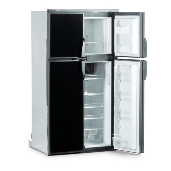
SectIon 1 1.1 refrigerator overview MODELS WITH MANUAL DOOR LOCKING SYSTEMS Control Panel LED Display Ice Bucket Manual Travel Latch Door Compartment Finned Cooling Plate Shelf Drip Protection Draining Pipe Crispers This is a general view of the appliance. The Model shown is equipped with ice maker. The number of shelves and door compartments may vary according to the model. - Page 8 SectIon 1 MODELS WITH THE AUTOMATIC DOOR LOCKING SYSTEM AND EQUIPPED WITH WATER DISPENSER Control Panel LED Display Ice Bucket AutomaticTravel Latch Water Dispenser not on all units Door Compartment Finned Cooling Plate Shelf Drip Protection Draining Pipe Crispers This is a general view of the appliance. The Model shown is equipped with ice maker and water dispenser.
- Page 9 SectIon 1 MODELS WITH THE AUTOMATIC DOOR LOCKING SYSTEM AND EQUIPPED WITH ICE AND WATER DISPENCER Control Panel LED Display Ice Box AutomaticTravel Latch Drip Tray top of lower door Door Compartment Finned Cooling Plate Drip Protection Draining Pipe Shelf Crispers This is a general view of the appliance.
- Page 10 Panel rm1350 & rme1350 refrigerator control Panels rm1350 display rme1350 display Main Power Button ON/OFF Press the button to turn the refrigerator on or off. 2. AUTO/GAS Mode Selector Button Press the button to turn the auto mode on or off.
- Page 11 led display Panel The LED display panel provides a quick visual indicator of the temperature of the food in the fresh food cabinet, status messages, and alarm conditions. For RM1350XXX, the AUTO and LP mode indication lamps show the mode of operation. led Panel IndIcatIonS StatuS InformatIon RM1350M,RM1350IM...
- Page 12 models With automatic door locking System The refrigerator is equipped with a travel latch that auto- matically locks the refrigerators doors when the RVs en- gine is running. When the RV’s engine is off, the travel latch unlocks the doors. 3.
-
Page 13: Leveling The Refrigerator
aBSorPtIon coolIng SyStem This is why we have a low ambient control. If it so hap- pens that the temperature in the refrigerator has satisfied In an absorption refrigerator system, ammonia is liquefied the thermostat setting, and the CUT-OUT threshold has in the finned condenser coil at the top rear of the refrig- been reached, the refrigerator cycles OFF. -
Page 14: Turning Off The Refrigerator
modeS of oPeratIon - auto and gaS turning off the refrigerator The refrigerator may be shut off while in any mode of op- auto mode eration by pressing the main power ON/OFF button (OFF When the refrigerator is in AUTO mode, it automatically position). -
Page 15: Ice Maker Operation
adjusting the Size of cubes temporary gas lockout In the Auto mode the gas operation will automatically be locked out for a period of 15 minutes when the engine is If the ice maker was cleaned and drained, no ice cubes will be dumped into the bin during the first cycle. -
Page 16: Water Dispenser
Ice & Water dispenser TO DISPENSE ICE, FOLLOW THESE STEPS: Insert a glass in the dispensing cavity and press the left lever. Do not turn the adjustment screw more than one revolution at a time. Allow the ice maker to cycle several times before another adjustment is made. -
Page 17: Ac Voltage
RM1350 34.3 ac Voltage reQuIrementS The RM1350 uses two AC heaters wired in series. The ohms resistance should be 34.3 ohms +/- 10%. this is an energized circuit. Shock can occur if not tested properly. testing is to be done by a qualified service technician. -
Page 18: Control Module Water Valve & Auger
3.3 control module for Water & auger troubleshooting control module Problem 1 The control module is used for two reasons: The water paddle is pushed but nothing happens, the LED light is off. • To shut off the 120 volt AC & 12 volt DC supply to action the door dispenser and icemaker auger when the 1. -
Page 19: Dc Voltage
DC power. The converter and alternator pro- duce DC power by a series of diodes that rectify alternat- ing current to DC. The Dometic control system will only tolerate up to 6 AC volts on the DC line. AC ripple can be measured by a digital voltmeter set on the AC and mea- sure at the main DC terminal block connections. -
Page 20: Thermistor
The RM1350 will not run constantly when the thermistor is unplugged or becomes an open circuit, be- 5.3 Igniter cause the RM1350 has a water tank in the refrigerator The igniter used on Dometic model refrigerators operates to provide chilled water for the dispenser. Failure of the on 12 volts DC. -
Page 21: High Voltage Cable
Do not use the Channel Mark 6, Model 12 E igniter. The RM1350 cooling unit has a thermofuse located on the boiler. The function of the thermofuse is to shut down the control system in the event of a cooling unit problem. -
Page 22: Control Panel
5.10 led display Panel Second, remove all wires from the switch assembly, then check the switch. When the switch is depressed, there should not be continuity. When the switch is NOT de- With the control panel in the OFF position, check for DC pressed, there should be continuity. -
Page 23: Lower Board
5.12 lower Board P1 To upper control / display board J4 Negative lead from thermocouple P2 Thermistor J11 To D+ treminal (TAG Line) P3 To gas valve and igniter J12 To activate interor light for low ambient control J1 Positive 12V DC from thermofuse / terminal block J6 AC neutral (White) J2 To interior light (switched) J7 AC heater... -
Page 24: Fuses
The AC voltage detection circuit is damaged. gas mode 12 Volt Valve note: the dometic control board used in the Water in Door rm1350 is a 3 try system in the gas mode. -
Page 25: Automatic Door Lock
5.17 Ventilator fans The RM1350 use two ventilator fans mounted to the back of the refrigerator (exterior). The purpose is to assist re- quired air movement across the refrigerator condenser to ensure optimum performance. - Page 26 typical rm1350m Wiring diagram...
- Page 27 typical rm1350mIm Wiring diagram...
- Page 28 typical rm1350Im Wiring diagram...
- Page 29 typical rm1350WIm Wiring diagram...
- Page 30 typical rm1350WId Wiring diagram...
-
Page 31: External Wiring
6.2 external Wiring 120 Volts ac Connection(s): The refrigerator is equipped with a three prong (grounded) plug for protection against shock hazards and should be plugged directly into a properly grounded three prong receptacle. DO NOT cut or remove the grounding prong from this plug. Units with icemaker may have a separate plug. -
Page 32: Orifice
3 slots. The control board reads negative millivolts DC from the thermocouple and the positive lead goes to the The Dometic orifice is a brass alloy with a man-made ruby pressed in the center that has been laser-beam drilled in ground terminal on the control board. -
Page 33: Burner
The flue tube must be cleaned periodically, at least once a year. Clean by using flue brush, Dometic Part no. 0151404001. 8.5 Flue Baffle The flue baffle (spiral baffle) is a twisted piece of metal... -
Page 34: Cooling Unit
SectIon 9 coolIng unIt typical roof Vent and Side Wall Vent 9.1 leveling Leveling is one of the requirements for proper operation of absorption refrigerators. The absorption design utilizes no mechanical pumps or compressors to circulate the re- frigerant within the system, so proper leveling must be maintained to provide the correct refrigerant flow. - Page 35 typical two Side Wall Vent application. always refer to Vent Instructions 3308666.xxx (Dimensions are in inches) Model Min. Min Dim. Min Dim. Min Dim. Vent +1/4, -0 Dim. Dim. Height RM 1350 27 - 1/16 5 - 1/8 4 - 5/8 44 - 1/2 tHe fan Placement dImenSIon to tHe refrIgerator floor...
- Page 36 refrIgerator VentIlatIon aIr cHannel KIt 3312270.XXX Min 26-7/8˝ Max 35-1/2˝ 26-5/16˝ 26˝ Min 6˝ Max 15˝ Full Width Baffle Side Vent Air Channel Fans 9/16˝ - 9˝ Crossbar Attacn With Screws Side Vent...
- Page 37 Maximum M i n i m u n Maximum Maximum Maximum Number Vent Height Dimension Dimension Dimension Dimension Dimension Dimension + 1/4˝ -0 + 1/4˝ -0 RM1350 63 3/16˝ 27 1/16˝ 33 1/16˝ 5 1/8˝ 14˝ 6˝ 1˝ Ventilator Fans...
-
Page 38: Air Leaks
9.3 air leaks 9.4 Interior liner Seal to frame Check the gasket on the doors to be sure of a positive There is a seal that is applied to the liner in the area air seal. A simple method to check gaskets is to close where the metal frame makes contact with the interior the door on a dollar bill, then pull the dollar bill out. -
Page 39: Door Position
If the frame between the doors is sweating the cli- and unit is level. If the RM1350 has water thru the door the mate control heater(s) should be tested. Section 5.6. - Page 40 © Dometic 2007 OS2177 MKTGCOMM...
-
Page 41: Error Codes
SectIon 11 diagnostic mode SectIon 10 error codes 11.1 diagnostic test The codes are displayed flashing (alternating between temperature and message) on the display. To perform a diagnostic test: No communication between display and power modules. Turn off the refrigerator. (press ON/OFF button) The control system will revert to full automatic operation Press and hold the TEMP. -
Page 42: Ice Maker
The refrigerator has to be connected to 120 volts AC before the ice maker can operate. The water line manual shutoff valve (not part of Dometic unit) must be open. To start making ice, move the ice level bail arm to DOWN position. -
Page 43: Shut Off Arm
12.5 Shut off arm 12.7 timing motor The shutoff arm is cam driven. It operates a switch to con- This is a low-wattage, stall-type motor which is geared to trol the quantity of ice produced. During the ejection cycle the timing cam and ice ejector. It is a one RPM motor. To the arm is raised and lowered during each of the two revo- check the motor, disconnect power to the appliance and lutions of the timing cam. -
Page 44: Ice Maker Replacement
12.11 Water Supply 12.9 Ice maker replacement To operate properly, the water pressure in the water sup- ply line must be between 15 and 50 PSI. Lower water pressure, water turned off, or obstructions or air in the wa- ter line can cause low or no ice production. First check to see that the water supply is fully turned on. - Page 45 DC Relay...
- Page 47 note tHe relatIVe PoSItIon of tHeSe comPonentS In tHe folloWIng ScHematIcS non energIzed cIrcuIt energIzed cIrcuIt after a few degrees of motor rota- tion, the timing cam switches the holding switch to its normally open position; this assures completion of the cycle.
- Page 48 once again after a few degrees of rotation the timing cam closes the Near the completion of the first rev- holding switch providing a circuit to olution, the timing cam closes the the motor that will assure completion water valve switch. However since of this revolution.
- Page 49 near the completion of the second revolution the timing cam again closes the water valve switch. this time a circuit is completed through the ejection cycle ends the mo- the water valve solenoid, its switch ment that the holding switch and mold heater.