Planet ICA-HM101 User Manual
Wired/wireless h.264 mega-pixel ip camera
Hide thumbs
Also See for ICA-HM101:
- Quick installation manual (2 pages) ,
- Quick installation manual (2 pages)
Table of Contents
Advertisement
Quick Links
Advertisement
Table of Contents

Related Manuals for Planet ICA-HM101


Summary of Contents for Planet ICA-HM101
- Page 1 User’s Manual ICA-HM101 / ICA-HM101W Wired / Wireless H.264 Mega-Pixel IP Camera...
- Page 2 Copyright Copyright © 2012 by PLANET Technology Corp. All rights reserved. No part of this publication may be reproduced, transmitted, transcribed, stored in a retrieval system, or translated into any language or computer language, in any form or by any means, electronic, mechanical, magnetic, optical, chemical, manual or otherwise, without the prior written permission of PLANET.
- Page 3 Do not dispose of WEEE as unsorted municipal waste and have to collect such WEEE separately. Revision User’s Manual for PLANET Wired/Wireless H.264 Mega-Pixel IP Camera Model: ICA-HM101 / ICA-HM101W Rev: 1.0 (April. 2012) Part No. EM-ICAHM101 Series_v1.0...
-
Page 4: Table Of Contents
Table of Content 1. Introduction......................5 1.1 Overview ....................5 1.2 Features ....................5 1.3 Package Contents ...................6 2. Basic Setup .....................7 2.1 System Requirement................7 2.2 Physical Description ................8 2.2.1 Terminal Connections ..............8 2.2.2 Bottom Panel ................9 2.2.3 Side Panel .................. 11 2.3 Initial Utility Installation ................13 2.4 Preparation....................15 2.4.1 Search and View by PLANET IP Wizard II........15 2.5 Using UPnP of Windows XP or Vista.............19... - Page 5 3.6.2. Privacy Mask ................54 3.7 System ....................55 3.7.1. System..................55 3.7.2. Date & Time ................56 3.7.3. Maintenance ................57 3.8 Video .....................59 3.8.1. Common ..................59 3.8.2. Video Profile ................60 3.8.3. ROI .....................61 3.9 Audio Configuration................62 3.10 User Privilege Access Configuration ...........63 3.11 E-Mail Configuration ................64 3.12 Object Detection .................65 3.13 Storage Configuration .................66 3.14 Recording List..................67...
-
Page 6: Introduction
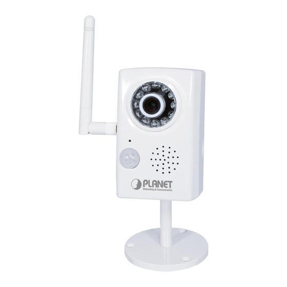
The ICA-HM101 features 0.5 lux illumination. 12 white LEDs built around the lens bring the clearest vision at night. The ICA-HM101 offers color pictures both in the day and night with built-in CMOS sensor supporting up to 10 meters. It also uses new High-Light LED to provide greater performance in the dark and longer life of LED. -
Page 7: Package Contents
Support both Variable Bit Rate and Variable Frame Rate 2 MP resolution or 720p mode selectable Up to 30fps for 1280x720 resolution and up to 15fps for 1600x1200 resolutions Digital WDR to provide clear images even under back light circumstances 3D de-noise to improve picture quality at low lux 2-Way audio with built-in microphone and speaker Sensor input and alarm output... -
Page 8: Basic Setup
1. The listed information is minimum system requirements only. Actual requirement will vary depending on the nature of your environment. 2. The ICA-HM101 series can be managed by PLANET IP Wizard II if you want to configure more detail information and settings of PLANET IP Wizard II software please refer to the CD-ROM folder “D:\Utility\IPWizardII\setup.exe”, assume D is... -
Page 9: Physical Description
2.2 Physical Description 2.2.1 Terminal Connections Front View User can attach the included antenna to antenna connector Antenna (SMA type) or use another high-gain antenna to get higher (ICA-HM101W only ) performance. These LEDs are White-light type by mode. It’s very useful for White-light LEDs low-lux environment to provide extra light source for image sensor Lens &... -
Page 10: Bottom Panel
2.2.2 Bottom Panel ICA-HM101 ICA-HM101W Audio/Video-out Jack allows this device to output audio and video signal. Audio/Video Use the attached A/V cable to connect A/V device where white cable is for Output Jack audio and yellow cable is for video. - Page 11 This button is hidden in the pinhole. This button is used to restore the all factory default settings. Sometimes restarting the camera will make the system back to a normal state. If the system still got problems after restart, user can restore the factory default settings and install it again. To restore the device, please follow the steps below: 1.
-
Page 12: Side Panel
2.2.3 Side Panel ICA-HM101/ICA-HM101W Micro-SD Card slot User can insert a micro SD card into this slot for event recording. -
Page 13: Hardware Installation
Hardware Installation 1. Attach the Camera with the included stand 2. Place the Camera on the table or fix it onto ceiling or wall Use three screws to fix the Network Camera onto the ceiling or wall. You could also put the Network Camera on the table directly. -
Page 14: Initial Utility Installation
4. Connect the external power supply to Camera Connect the attached power adapter to the DC power jack of the IP Camera. Note: Use the power adapter, 12VDC, included in the package and connect it to wall outlet for AC power. Once you have installed the IP Camera well and powered it on, the network accessing type LED will turn on. - Page 15 If the welcome screen does not appear, click “Start” at the taskbar. Then, select NOTE: “Run” and type “D:\Utility\IPWizard II\setup.exe”, assume D is your CD-ROM drive. 3. The “Welcome to the InstallShield Wizard for PLANET IP Wizard II” prompt will display on the screen and click “Next”...
-
Page 16: Preparation
5. Please click “Install” to start the installation. 6. Please click “Finish” to complete the installation and launch program immediately. 2.4 Preparation When you installed the Internet Camera on a LAN environment, you may execute PLANET IP Wizard II to discover camera’s IP address and set up related parameters in the camera. 2.4.1 Search and View by PLANET IP Wizard II When you installed the Internet Camera on a LAN environment, you have two easy ways to search your cameras by PLANET IP Wizard II or UPnP discovery. - Page 17 Search When launch the Planet IP Wizard II, a searching windows will pop up. Planet IP Wizard II is starting to searching Internet Cameras on the LAN. The existed devices will be listed as below.
- Page 18 View If Planet IP Wizard II finds Internet Camera, View button will be available. Please select the camera you want to view and click the View button. Then you could see the Video from camera directly. Furthermore you could double click the left button of mouse to link to the Internet Camera by browser.
- Page 19 In case, you do not want to change username and/or password, then just click “Submit” button to perform your setting accordingly. Click “<<” button will go back to previous page. If you like to change username and/or password of the device, just click the check button. Then, the related fields will show up as below.
-
Page 20: Using Upnp Of Windows Xp Or Vista
2.5 Using UPnP of Windows XP or Vista 2.5.1 Windows XP UPnP™ is short for Universal Plug and Play, which is a networking architecture that provides compatibility among networking equipment, software, and peripherals. This device is an UPnP enabled device. If the operating system, Windows XP, of your PC is UPnP enabled, the device will be very easy to configure. - Page 21 The following screen will appear, select “Networking Services” and click “Details” to continue. The “Networking Services” will display on the screen, select “Universal Plug and Play” and click “OK” to continue.
- Page 22 Please click “Next” to continue. The program will start installing the UPnP automatically. You will see the below pop-up screen, please wait while Setup configures the components.
- Page 23 Please click “Finish” to complete the UPnP installation Double-click “My Network Places” on the desktop, the “My Network Places” will display on the screen and double-click the UPnP icon with Internet Camera to view your device in an internet browser.
-
Page 24: Windows Vista
ICA-HM101 – 00304f0a145a 2.5.2 Windows Vista UPnP™ is short for Universal Plug and Play, which is a networking architecture that provides compatibility among networking equipment, software, and peripherals. This device is an UPnP enabled device. If the operating system, Windows Vista, of your PC is UPnP enabled, the device will be very easy to configure. -
Page 25: Setup Activex To Use The Internet Camera
Double-click “My Network Places“ on the desktop, the “My Network Places” will display on the screen and double-click the UPnP icon with Internet Camera to view your device in an internet browser. ICA-HM10 – 00304fA15076 2.6 Setup ActiveX to use the Internet Camera The Internet Camera web pages communicate with the Internet Camera using an ActiveX control. -
Page 26: Internet Explorer 7 For Windows Xp
setup your “Settings” as follow. Set the first 3 items • Download the signed ActiveX controls • Download the unsigned ActiveX controls • Initialize and script the ActiveX controls not masked as safe to Prompt By now, you have finished your entire PC configuration for Internet Camera. 2.6.2 Internet Explorer 7 for Windows XP From your IE browse ”Tools”... -
Page 27: Internet Explorer 7 For Windows Vista
By now, you have finished your entire PC configuration for Internet Camera. 2.6.3 Internet Explorer 7 for Windows Vista From your IE browse ”Tools” ”Internet Options…” ”Security” ”Internet” ”Custom Level…”, please setup your “Settings” as follow. • Enable “Automatic prompting for ActiveX controls” •... - Page 28 • Enable “Automatic prompting for ActiveX controls” • Prompt “Initialize and script active controls not marked….” By now, you have finished your entire PC configuration for Internet Camera.
-
Page 29: Web-Based Management
3. Web-based Management This chapter provides setup details of the Internet Camera’s Web-based Interface. 3.1 Introduction The Internet Camera can be configured with your Web Browser. Before configure, please make sure your PC is under the same IP segment with Internet Camera. 3.2 Connecting to Internet Camera Use the following procedure to establish a connection from your PC to the Internet Camera. - Page 30 Click on the message, and click Install ActiveX Control… When you see this message, click Install’ to install required ActiveX control After the ActiveX control was installed and run, the first image will be displayed. You should be able to see the images captured from the Internet Camera in the web page now. For advanced functions, please refer to instructions given in follows chapters.
-
Page 31: Live View
3.3 Live View Start-up screen will be as follow no matter an ordinary users or an administrator. Video Profile ActiveX Control Streaming Protocol Language Monitor Image Section Setting Menu Client Menu Video Information 2-Way Audio Full Screen Monitor Image The image shot by the camera is shown here. The date and time are Section displayed at the top of the window. - Page 32 control within Microsoft® Internet Explorer. Setting Menu This function is detail setting for the camera that only available for user logged into camera as administrator. Item Action Configure Network settings such as Wireless, Network IPv6, ONVIF, DHCP, DDNS, 3GPP, PPPoE and UPnP.
-
Page 33: Activex Control
3.4 ActiveX Control The plug-in ActiveX control supports a lot of functions by clicking the left mouse button. Note that this feature only supports on the ActiveX control within Microsoft® Internet Explorer. On the ActiveX control icon, click the Left Mouse Button, then a menu pop-up. This menu provides features that are unique to the ActiveX control. -
Page 34: Digital Zoom
3.4.1. Digital Zoom Click Digital Zoom to active this function as above. User can drag or scale the box over the video to adjust zoom ratio and position. 3.4.2. Record Click Record to activate this function. Press Record button to start recording. The video file is saved as ASF format into your local PC. -
Page 35: Snapshot
3.4.3. Snapshot Click Snapshot to activate this function. Press Snapshot button to take a picture. The image file is saved as JPEG format into your local PC. Select Browser, the pop-up window to select the save path and file name prefix, select OK to continue. If you like to retrieve the saved image, select the file to display the saved image by using any one of graph editing tools. -
Page 36: About
3.4.5. About Click About to show the ActiveX information 3.5 Network Configuration Use this menu to configure the network to connect the device and the clients. 3.5.1. Network This section provides the menu of connecting the device through Ethernet cable. MAC address Display the Ethernet MAC address of the device. - Page 37 address within limited tries, the device will assign a default IP address for 192.168.0.20. If you do not select “Obtain an IP address automatically”, then you need to enter these network parameters by yourself. IP Address This address is a unique numbers that identifies a computer or device on the WAN or LAN.
-
Page 38: Wireless (Ica-Hm101W Only)
If multiple devices are installed on the LAN and also required to be accessed from the WAN, then the HTTP Port can be assigned as the virtual server port mapping to support multiple devices. NOTE When the configuration is finish, please click “OK” to save and enable the setting. - Page 39 wireless”: Choose wired or wireless mode. However, note that wired is priority. Type To select one of WLAN modes from Infrastructure or Ad-Hoc mode. Security mode Shows which type of security the network uses. The device supports three security methods: None, WEP, WPA_PSK, WPA2_PSK Obtain DNS from Enable this checked box when a DHCP server is installed on the DHCP...
- Page 40 Obtain IP address Enable this checked box when a DHCP server is installed on the automatically (DHCP) network to issue IP address assignment. With this setting, the IP address is assigned automatically. IP address, Subnet If you do not select Obtain an IP address automatically, then you need mask, and Gateway to enter these network parameters manually.
- Page 41 5. ICA-HM101W restarting to enable wireless function. 6. Wait for wireless ready 7. Plug out cable to enable wireless function...
-
Page 42: Ipv6 Function
3.5.3. IPv6 function Internet Protocol version 6 (IPv6) is called the “IP Next Generation” (IPng), which is designed to fix the shortcomings of IPv4, such as data security and maximum number of user addresses. It is backward compatible and thus expected to slowly replace IPv4, with the two existing side by side for many years. -
Page 43: Https
3.5.4. HTTPS HTTPS: Stands for Hypertext Transfer Protocol Secure HTTPS is a combination of the Hypertext Transfer Protocol with the SSL/TLS protocol to provide encrypted communication and secure identification of a network web server. HTTPS connections are often used for sensitive transactions in corporate information systems. The main idea of HTTPS is to create a secure channel over an insecure network. - Page 44 Your Internet Service Provider (ISP) provides you at least one IP address which you use to connect to the Internet. The address you get may be static, meaning it never changes, or dynamic, meaning it’s likely to change periodically. Just how often it changes, depends on your ISP. A dynamic IP address complicates remote access since you may not know what your current WAN IP address is when you want to access your network over the Internet.
-
Page 45: Pppoe
3.5.6. PPPoE PPPoE: Stands for Point to Point Protocol over Ethernet A standard builds on Ethernet and Point-to-Point network protocol. It allows Internet Camera connect to Internet with xDSL or cable connection; it can dial up your ISP and get a dynamic IP address. -
Page 46: Streaming
3.5.7. Streaming RTSP is a streaming control protocol, and a starting point for negotiating transports such as RTP, multicast and Unicast, and for negotiating codecs. RTSP can be considered a "remote control" for controlling the media stream delivered by a media server. RTSP servers typically use RTP as the protocol for the actual transport of audio/video data. -
Page 47: Upnp
1.Choose a verified player (PacketVideo, Quicktime or Realplayer Dialing currently) procedure 2. Use the following URL to access: rtsp://host/mpeg4/media.3gp Where host is the host name or IP address of the camera. Compatible Please contact your dealer to get the approved list of compatible 3G 3G mobile phone. -
Page 48: Bonjour
must be enabled in the NAT router first. Port Range The port range will open in NAT router. External IP address Show the IP address and port for WAN access through Internet. If NAT traversal is configured successfully, user can use this IP address and port to access this device. -
Page 49: Onvif
3.5.10. ONVIF ONVIF is a global and open industry forum with the goal to facilitate the development and use of a global open standard for the interface of physical IP-based security products. Or in other words, to create a standard for how IP products within video surveillance and other physical security areas can communicate with each other. -
Page 50: Ip Filter
3.5.11. IP Filter You can enter different user’s IP address which are allowing enter or denying by the device. IP Filter To enable or disable the IP filter function here. IP Filter Policy Choose the filter policy where is denying or allowing. -
Page 51: Ip Notification
3.5.12. IP Notification In case the IP address is changed, system is able to send out an email to alert someone if the function is enabled. If enable this function, then the “Send to“ and “Subject” field SMTP Notification (e-mail) need to be filled. - Page 52 HTTP Login Password Type the password for the HTTP server. Proxy Address Type the server name or the IP address of the HTTP Proxy. Proxy Port Set port number of Proxy. Proxy Login name Type the user name for the HTTP Proxy. Proxy Login Password Type the password for the HTTP Proxy.
-
Page 53: Camera Configuration
3.6 Camera Configuration Use this menu to set the function of the camera of Internet Camera 3.6.1. Picture Rotation Turn the “Mirror” and “Vertical Flip” On or OFF. The image will be overturned as below. Auto: will adjust the white balance automatically. White Balance Hold: will hold the white balance. - Page 54 Auto: will adjust the internal gain automatically. Exposure Control Hold: will hold the internal gain. Maximum Exposure User can limit the maximum exposure time of the image sensor. Time The larger value means longer exposure time possibly. Color Level Large value will be colorful. Brightness Large value will brighten camera.
-
Page 55: Privacy Mask
3.6.2. Privacy Mask Use this page to specify privacy mask window 1 to window 8 and set the name and gray level for selected window. Add and Delete To add or delete the privacy mask windows, user can specify up to 7 windows to mask the video captured by this device. -
Page 56: System
3.7 System Use this menu to perform the principal settings of Internet Camera. 3.7.1. System Device title You can enter the name of this unit here. It’s very useful to identify the specific device from multiple units. Software version This information shows the software version in the device. Network LED Switch the LED light of this Internet Camera on or off, that Network LEDs will stop working, in case you don’t want other people know the... -
Page 57: Date & Time
3.7.2. Date & Time User can setup the time setting of Internet Camera, make it synchronized with PC or remote NTP server. Also, you may select the correct time zone of your country. Server Date & Time Displays the date and time of the device PC Time Displays the date and time of the connected PC Synchronize... -
Page 58: Maintenance
Daylight Saving Sets up the date and time of daylight saving stop time. Stop Time Daylight Saving Sets up the date of daylight saving offset. Offset 3.7.3. Maintenance Default Settings Recall the device hard factory default settings. Note that click (Include the network this button will reset all device’s parameters to the factory setting) - Page 59 2. Make sure that only you access this device at this moment 3. Disable Motion Detection function. 4. Select “Firmware name” 5. Select the Firmware binary file. Note : That it must make sure that the Firmware only applies to this device, once update, it will be burned into FLASH ROM of system.
-
Page 60: Video
3.8 Video This device provides 2 modes of video profile. The first one is Mega-pixel mode which supports video resolution up to Mega-pixel. However the maximum frame rate of this mode is up to 15fps only. The second one is VGA mode which supports video resolution up to VGA but frame rate can be up to 30fps. -
Page 61: Video Profile
3.8.2. Video Profile User can modify the detail parameter for each video profiles in this page. Name To assign a name to the selected profile. Video Type Video codec of the selected profile. Resolution Resolution of the selected profile. Assign the selected profile as a ROI stream or not. (Only available for the profiles with max resolution) Rate Control Defines the rate control method of this profile. -
Page 62: Roi
For ECBR, the video bitrates is based on normal CBR mode. However, the target bitrates can be increased to max target bitrate while lots of motion in video. The max target bitrates will keep a pre-defined time period and then back to normal CBR bitrates. For EVBR, the video bitrates is based on normal VBR mode. -
Page 63: Audio Configuration
3.9 Audio Configuration It’s M-JPEG mode in this profile. Audio To enable or disable audio function. Audio type To select G711 or G726 for audio coding. Audio Mode: To select Simplex or Full duplex (2-way audio) mode. Input Gain: To adjust gain of input audio. Output Gain: To adjust gain of output audio. -
Page 64: User Privilege Access Configuration
3.10 User Privilege Access Configuration Use this menu to set the user names and password of the Administrator and up to 10 users, and access right of each user. Viewer Login Select “Anonymous” to allow any one viewing the video once connected. -
Page 65: E-Mail Configuration
3.11 E-Mail Configuration You may setup SMTP mail parameters for further operation of Event Schedule. That’s, if users want to send the alarm message out, it will need to configure parameters here and also add at least one event schedule to enable event triggering. SMTP Server Type the SMTP server name or the IP address of the SMTP server. -
Page 66: Object Detection
3.12 Object Detection Use this menu to specify motion detection window 1 to window 4 and set the conditions for detection while observing a captured image. Add and Delete To add or delete the motion windows. User can specify up to 4 Included and/or Excluded windows to monitor the video captured by this device. -
Page 67: Storage Configuration
3.13 Storage Configuration This page shows the status of attached SD card and Samba server. You may setup related parameters to manage the attached SD card or Samba server also. Enable automatic disk cleanup Delete old recorded files while the conditions are reached as below. -
Page 68: Recording List
3.14 Recording List iles list inside the SD Card This page shows the files list information, f . User may reload file from SD card that play or remove the selected file. This page shows the files list information, files list inside the SD Card or Samba server. User may reload file from SD card or Samba server that play or remove the selected file. -
Page 69: Continuous Recording
3.15 Continuous Recording You m ay enable or disable continuous recording function here. Select SD card or Samba server for storage destination. Note : When enable continuous recording that press restart will delete correct recording... -
Page 70: Event Server Configuration
3.16 Event Server Configuration 3.16.1 FTP Server You may setup FTP parameters for further operation of Event Schedule. That’s, if users want to send the alarm message to an FTP server, it will need to configure parameters here and also add at least one event schedule to enable event triggering as SMTP. -
Page 71: Tcp Server
3.16.2 TCP Server In addition to send video file to FTP server, the device also can send event message to specified TCP server. Name User can specify multiple TCP servers as wish. Therefore, user needs to specify a name for each TCP server setting. TCP Server Type the server name or the IP address of the TCP server. -
Page 72: Http Server
3.16.3 HTTP Server The device also can send event message to specified HTTP server. Name User can specify multiple HTTP servers as wish. Therefore, user needs to specify a name for each HTTP server setting. Type the server name or the IP address of the HTTP server. Test Check the HTTP server whether it is available or not. -
Page 73: Samba Server
3.16.4 SAMBA Server The device also can send video stream to specified SAMBA server. Most of the time, the SAMBA server will be another PC or NAS server. Name User can specify multiple HTTP servers as wish. Therefore, user needs to specify a name for each HTTP server setting. SAMBA Server Type the server name or the IP address of the SAMBA server. -
Page 74: Event Schedule Configuration
3.17 Event Schedule Configuration This menu is used to specify the schedule of Events and activate the some actions provided by this device. Name Name of the Event or Schedule. Enable Enable or disable this Event or Schedule. Type Schedule start with Event trigger or Schedule trigger. Enable Time Define the feasible time slot. - Page 75 Example1. Send file to FTP server by motion triggered always: Select event trigger Enable time: start from 00:00 to 24:00 every day Trigger by: Motion Area (Added in Object Detection page) Action : Send FTP (Add in Event Server -> FTP Server page)
- Page 76 Example2. Send file to E-Mail server by motion triggered from Friday 18:00 to Saturday 06:00 Select event trigger. Enable time: start from Friday 18:00 and keep work in 12 hours, so it will stop on Saturday 06:00. Trigger by : Motion Area (Added in Object Detection page) Action : Send e-mail (Add in E-Mail page) To email address: You need to input the receiver email address.
- Page 77 Example3. Enable Voice Alert every 10-minute during 18:00 to 24:00 from Monday to Friday. 1. Type: Select schedule trigger and interval is 10-minute. 2. Enable Time: Select Monday to Friday, and set start time from 18:00 and keep work in 6 hours. 3.
-
Page 78: Record Configuration
3.18 Record Configuration User can choose the type of record file for event or schedule application. Record File Type Choose AVI or JPEG file format for record file. Record File Prefix Define the prefix of recorded filename. Pre-Trigger Duration Define the maximum duration of pre-alarm. Best Effort Duration Define the best effort duration of post-alarm. -
Page 79: Appendix A: Ping Ip Address
Appendix A: PING IP Address The PING (stands for Packet Internet Groper) command is used to detect whether a specific IP address is accessible by sending a packet to the specific address and waiting for a reply. It’s also a very useful tool to confirm Internet Camera installed or if the IP address conflicts with any other devices over the network. -
Page 80: Appendix B: 3Gpp Access
Appendix B: 3GPP Access To use the 3GPP function, in addition to previous section, you might need more information or configuration to make this function work. That to use the 3GPP function, it strongly recommends to install the Networked Device Note with a public and fixed IP address without any firewall protection. -
Page 81: Appendix C: Bandwidth And Video Size Estimation
Appendix C: Bandwidth and Video Size Estimation The frame rate of video transmitted from the Internet Camera depends on connection bandwidth between client and server, video resolution, codec type, and quality setting of server. Here is a guideline to help you roughly estimate the bandwidth requirements for your Internet Camera. The required bandwidth depends on content of video source. -
Page 82: Appendix D: Ddns Application
Appendix D: DDNS Application 1. Preface If you have a Cable modem or xDSL, this is a great way to host your own Networked Device or other TCP/IP Service. Get your own domain like www.yourname.com, www.yourname.com.tw etc. (Note: This domain must be registered with Internic via registration authorities such as Network Solutions, DirectNIC, Register.com etc). - Page 83 (4). Fill the application agreement and necessary information. a. Username b. E-mail address and confirmation c. Password and confirmation d. Submit all the input information and finish creating an account...
- Page 84 Click these two options (5). Check your e-mail mailbox. There will be an e-mail with a title “Your DynDNS Account Information“. Click the hyperlink address to confirm the DDNS service that you just applied. Click to confirm Then DDNS you applied activated.
- Page 85 (6). Enter the web page http://www.dyndns.org/ again. Input your username and password that you just applied to login administration interface of DDNS server. Input your account (7). If the correct username and password are input, you can see the following picture at the top-right of the login page.
- Page 86 (9). Click the “ Dynamic DNS ”. (10). Click the “Create Hosts”. (11). We could create a domain name without any charge at this step. First, we input the host name. (No.1) Then we pick a domain that is easy to remember. Finally (No.2), click the “Add Host”...
- Page 87 5. Configure PLANET DDNS steps: Step 1: Enable DDNS option through accessing web page of NAS Step 2. Select on DDNS server provide, and register an account if you do not use yet. http://planetddns.com Let’s take dyndns.org as an example. Register an account in...
-
Page 88: Appendix E: Configure Port Forwarding Manually
Appendix E: Configure Port Forwarding Manually The device can be used with a router. If the device wants to be accessed from the WAN, its IP address needs to be setup as fixed IP address, also the port forwarding or Virtual Server function of router needs to be setup. - Page 89 Your WAN IP Address will be listed here. 3. Open/set Virtual Server Ports to enable remote image viewing The firewall security features built into the router and most routers prevent users from accessing the video from the device over the Internet. The router connects to the Internet over a series of numbered ports.
- Page 90 Enter valid ports in the Virtual Server section of your router. Please make sure to check the box on this line to enable settings. Then the device can be access from WAN by the router’s WAN IP Address. By now, you have finished your entire PC configuration for this device.
-
Page 91: Appendix F: Power Line Frequency
Appendix F: Power Line Frequency COUNTRY VOLTAGE FREQUENCY COMMENTS *Neutral and line wires are reversed from that Argentina 220V 50 Hz used in Australia and elsewhere. *Outlets typically controlled by adjacent switch. Australia 230V* 50 Hz Though nominal voltage has been officially changed to 230V, 240V is within tolerances and commonly found. -
Page 92: Appendix G: Troubleshooting & Frequently Asked Questions
Appendix G: Troubleshooting & Frequently Asked Questions Features The video and audio codec is The device utilizes H.264, MPEG-4 and M-JPEG triple compression adopted in the device. to providing high quality images. Where H.264 and MPEG-4 are standards for video compression and M-JPEG is a standard for image compression. - Page 93 PLANET IP Wizard II program Re-power the device if cannot find the unit within 1 minutes. cannot find the device. Do not connect device over a router. PLANET IP Wizard II program cannot detect device over a router. If IP address is not assigned to the PC which running PLANET IP Wizard II program, then PLANET IP Wizard II program cannot find device.
- Page 94 The port number assigned in your Internet Camera might not be available via Internet. Check your ISP for available port. The proxy server may prevent you from connecting directly to the Internet Camera, set up not to use the proxy server. Confirm that Default Gateway address is correct.
- Page 95 be accessed outside your local LAN. Check the bandwidth of Internet connection. If the Internet bandwidth is lower than target bit rate, the video streaming will not work correctly. The unreadable characters are Use the operating system of the selected language. Set the displayed.
- Page 96 24 bit or higher if possible within your computer. The configuration on the device image display is incorrect. You need to adjust the image related parameters such as brightness, contrast, hue and sharpness properly. Image flickers. Wrong power line frequency makes images flicker. Make sure the 50 or 60Hz format of your device.
-
Page 97: Appendix H: Product Specification
Appendix H: Product Specification Product ICA-HM101 ICA-HM101W Camera Image Sensor 1/3” 2 Mega-Pixel CMOS image sensor 4.3 mm, F1.8 Lens View Angle (Horizontal / Vertical) 56 / 43 Degree Effective Pixels 1600x1200 (UXGA) 0.5 lux @ F1.2 Min Illumination 42 dB... - Page 98 IEEE 802.3 / IEEE 802.3u / Network Standard IEEE 802.3 / IEEE 802.3u IEEE 802.11 b/g/n Security WEP and WPA encryption TCP/IP, UDP, HTTP, SMTP, FTP, NTP, DNS, DDNS, DHCP, Network Protocol ARP, Bonjour, UPnP, RTSP, RTP, RTCP, PPPoE, 3GPP, ICMP Microsoft ®...