Table of Contents
Advertisement
Quick Links
dVm series
direct Vent gas fireplace
models: 500dVm, 600dVm
Installation & Operating
Instructions
warnIngs
If the InformatIon In these InstructIons
are not followed exactly, a fIre
or explosIon may result causIng
property damage, personal Injury or
loss of lIfe.
– do not store or use gasoline or other
flammable vapors and liquids in the vicinity
of this or any other appliance.
– what to do If you smell gas
• do not try to light any appliance.
• do not touch any electrical switch; do not
use any phone in your building.
• Immediately call your gas supplier from
a neighbor's phone. follow the gas
supplier's instructions.
• If you cannot reach your gas supplier, call
the fire department.
– Installation and service must be performed
by a qualified installer, service agency or
the gas supplier.
warnIng: Improper installation, adjustment,
alteration, services or maintenance can cause
injury or property damage. refer to this manual.
for assistance or additional information
consult a qualified installer, service agency or
the gas supplier.
this appliance may be installed in an oem installation
in manufactured home (usa only) or mobile home
and must be installed in accordance with the
manufacturer's instructions and the manufactured
home construction and safety standard, Title 24
CFR, Part 3280 or Standard for Installation in Mobile
Homes. CAN/CSA Z3-240MH.
this appliance is only for use with the type(s) of
gas indicated on the rating plate unless a certified
kit is used.
warnIng
due to hIgh temperatures, the a pplIance
should Be located out of traffIc and
away from furnIture and draperIes.
chIldren and adults should Be alerted
to the haZards of hIgh surface
temperature and should stay away to
aVoId Burns or clothIng IgnItIon.
young chIldren should Be superVIsed
when they are In the same room as the
applIance.
clothIng or other flammaBle materIal
should not Be placed on or near the
applIance.
Keep the room area clear and free
from comBustIBle materIals, gasolIne,
and other flammaBle Vapors and
lIquIds.
Installer: leave this manual with the appliance.
consumer: retain this manual for future refer-
ence.
752523
DVM MDV cover
75D2525 1/11 Rev. 7
Advertisement
Table of Contents

Related Manuals for Majestic 500DVM


Summary of Contents for Majestic 500DVM
- Page 1 Installation & Operating Instructions warnIngs If the InformatIon In these InstructIons are not followed exactly, a fIre or explosIon may result causIng property damage, personal Injury or loss of lIfe. – do not store or use gasoline or other flammable vapors and liquids in the vicinity of this or any other appliance. – what to do If you smell gas • do not try to light any appliance. 752523...
-
Page 2: Table Of Contents
DVM Series Direct Vent Gas Fireplace thank you and congratulations on your purchase of a majestic fireplace. please read the InstallatIon and operatIon InstructIons Before usIng the applIance! Important: read all instructions and warnings carefully before starting installation. failure to follow these instructions may result in a possible fire hazard and will void the warranty. Important safety Information ........3 check gas pressure - signature command system ......35 code approval .............4 electrical wiring - scs ..........35 product features ............5 Junction Box Wiring ..........36 High Elevations ............5 Command Center Wall Installation ......36 Gas Pressures ............5 Wall Switch Installation .........36 Gas Specifications &... -
Page 3: Important Safety Information
Important safety InformatIon DVM Series Direct Vent Gas Fireplace owner Installer Please retain these instructions for future reference. Please leave these instructions with the appliance. • read this owner’s manual carefully and completely before trying to assemble, operate, or service this fireplace. • any change to this fireplace or its controls can be dangerous. • Improper installation or use of this fireplace can cause serious injury or death from fire, burns, explosions, electrical shock and carbon monoxide poisoning. This fireplace is a vented product. This fireplace must be 4. -
Page 4: Code Approval
Important safety InformatIon DVM Series Direct Vent Gas Fireplace Important: 14. Do not use any solid fuels (wood, coal, paper, card- please read the followIng board, etc.) in this fireplace. Use only the gas type carefully indicated on rating plate. It is normal for fireplaces fabricated of steel 15. -
Page 5: Product Features
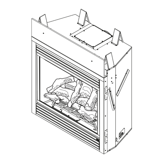
The appliance must be properly connected to a venting Nailing system. Flange • The appliance is not approved for closet or recessed installations. Figure 1 - 5/8" 500DVM and 600DVM Fireplace Nailing Flange (Millivolt Unit Shown — Also Available with Signature Command System) 1/2" Nailing Hi/Lo Knob Flange Off/Pilot/On Knob do not remove insulation board. -
Page 6: Fireplace & Framing Dimensions
Min. Rough Opening Height 5” 5/8” 2” 1/2” 1/2” Figure 2 - 5/8” Fireplace & Framing Dimensions 2 ” (64 mm) ref. 500dVm 600dVm 41" (1041 mm) 47" (1194 mm) 46B\zn" (1176 mm) 46B\zn" (1176 mm) 752525 DVM MDV dims 40C\," (1026 mm) 40C\,"... -
Page 7: Pre-Installation Information
pre-InstallatIon InformatIon DVM Series Direct Vent Gas Fireplace Before you start fIreplace framIng Read this homeowner manual thoroughly and follow all Firebox framing can be built before or after the appliance instructions carefully. Inspect all contents for shipping is set in place. Refer to Figure 2 for firebox dimensions and damage and immediately inform your dealer if any damage framing. -
Page 8: Fireplace Location
pre-InstallatIon InformatIon DVM Series Direct Vent Gas Fireplace fIreplace locatIon Plan for the installation of your appliance. This includes determining where the unit is to be installed, the vent configuration to be used, framing and finishing details, and whether any optional accessories (i.e. -
Page 9: Clearances
clearances DVM Series Direct Vent Gas Fireplace clearances to comBustIBles follow these instructions carefully to ensure safe installation. failure to follow instructions exactly can create a fire hazard. the appliance cannot be installed on a carpet, tile or other combustible material other than wood flooring. If installed on carpet or vinyl flooring, the appliance shall be installed on a metal, wood or noncombustible material panel extending full width and depth of the appliance. Stud 12” Header Side Wall 10” Standoff 8” 12" 6” Insulation 10 ” Combustible 4” Board Mantel 9 ”... -
Page 10: Secure Fireplace
secure fIreplace to floor or framIng DVM Series Direct Vent Gas Fireplace The fireplace must be secured to the floor and/or to framing studs as shown in Figure 6 . Use two (2) wood screws or masonry/ concrete screws to secure fireplace to the floor. Use four (4) screws to attach fireplace to framing. -
Page 11: Optional Top Vent Application
optIonal top Vent applIcatIon DVM Series Direct Vent Gas Fireplace optIonal top Vent applIcatIon after conversion to top vent configuration The appliance is shipped as a rear vent unit. If the installa- the 5" (127 mm) flue pipe should be tion layout requires the unit to be a top vent configuration concentric with the 8" (203 mm) outer collar ... -
Page 12: Venting Installation
VentIng InstallatIon DVM Series Direct Vent Gas Fireplace read all instructions completely and thoroughly before attempting installation. failure to do so could result in serious injury, property damage or loss of life. operation of improperly installed and maintained venting system could result in serious injury, property damage or loss of life. failure to follow these instructions will void the warranty. InstallatIon precautIons Consult local building codes before beginning the installation. The installer must make sure to select the proper vent system for installation. Before installing vent kit, the installer must read this fireplace manual and vent kit instructions. -
Page 13: Installation Clearances
VentIng InstallatIon DVM Series Direct Vent Gas Fireplace horizontal sections of this vent system require a minimum of 3” clearances to combustibles at the top of the flue and 1” clearance at the sides and bottom until the flue penetrates the outside wall. a minimum 1” clearance all around the flue is acceptable at this point of penetration. If vertical rise is 7Z\x” feet or higher when top venting, the clearance to combustibles is 1” on all sides of the horizontal run. Vertical sections of this vent system require a minimum of 1” clearance to combustibles on all sides of the pipe. this fireplace must be vented to the outside. the venting system must neVer be attached to a chimney serving a separate solid fuel burning appliance. each gas appliance must use a separate vent system. do not use common vent systems. *3” **1” *3" **1" **1” **1" 48 ” 34 ” (1226 mm) (880 mm) FP2412 Figure 10 - * A minimum of 3" clearance to the top is Combustible Clearances for Vent Pipe required along horizontal length until flue pipe penetrates outside wall. -
Page 14: Installation Planning
VentIng InstallatIon DVM Series Direct Vent Gas Fireplace InstallatIon plannIng never run the vent pipe down. this may There are two basic types of direct-vent installation: cause excessive temperatures which could • Horizontal Termination cause a fire. • Vertical Termination It is important to select the proper length of vent pipe for the type of termination you choose. -
Page 15: Termination Location
VentIng InstallatIon DVM Series Direct Vent Gas Fireplace general VentIng InformatIon - termInatIon locatIon INSIDE CORNER DETAIL G V H A D E L C B B V Fixed B V Closed V Fixed Operable Closed F V B M V B J B Figure 11 - I ... -
Page 16: Termination Clearances
VentIng InstallatIon DVM Series Direct Vent Gas Fireplace Termination Clearances Termination clearances for buildings with combustible and noncombustible exteriors. Inside Corner Alcove Applications* Outside Corner Combustible 6" (152 mm) Combustible 6" (152 mm) Noncombustible 2" (51 mm) Noncombustible 2" (51 mm) Balcony - Balcony - with no side wall... -
Page 17: Rear Wall Vent Installation
VentIng InstallatIon DVM Series Direct Vent Gas Fireplace rear wall Vent InstallatIon 2. Refer to the venting and termination instructions for further instructions. (5" 8" VentIng only) 3. Locate and cut the vent opening in the wall. For com- When installed as a rear vent unit this appliance may be bustible walls first frame in opening. -
Page 18: Horizontal With Vertical Rise (Through-The-Wall)
VentIng InstallatIon DVM Series Direct Vent Gas Fireplace 6. Slide the wall thimble over the vent pipe before con- necting the horizontal run to the vent cap. Figure 19 7. Carefully move the fireplace with vent assembly attached toward the wall and insert the vent pipe into the horizontal termination. - Page 19 VentIng InstallatIon DVM Series Direct Vent Gas Fireplace when installing the appliance as a rear vent unit, the 90°, 45° transition elbow attached directly to the rear of the unit is not Included in the following criteria and calculations, and unless specifically mentioned should be ignored when calculating venting layouts. • The maximum number of 90° elbows per side wall installation is three (3). Figure 20 •...
- Page 20 VentIng InstallatIon DVM Series Direct Vent Gas Fireplace • The maximum number of 45° elbows permitted per side 10Z\x" wall installation is two (2). These elbows can be installed (267 mm) in either the vertical or horizontal run. • For each 45° elbow installed in the horizontal run, the length of the horizontal run MUST be reduced by 18"...
-
Page 21: Below Grade Installation
VentIng InstallatIon DVM Series Direct Vent Gas Fireplace 9Z\x" Screws (241 mm) Firestop Minimum 9Z\x" 4" Clearance (241 mm) Ground Window 24” Well framing Minimum combustible wall Gravel Drain 7Z\x" (190 mm) Foundation Wall Figure 27 - FP1965 Below Grade Installation Figure 26 - VO584-100 5. -
Page 22: Vertical Through-The-Roof Installation
VentIng InstallatIon DVM Series Direct Vent Gas Fireplace VertIcal through-the-roof applIca- tIons a restrictor disc must be installed on any vertical termination that is higher than Maximum 12'. Height 10' Maximum Minimum Height Install restrictor disc as shown in Figure 29 for vertically vented applications. Up to three (3) restrictor discs may be needed for 40' installation. -
Page 23: Installation For Vertical Termination
VentIng InstallatIon DVM Series Direct Vent Gas Fireplace Example: Elbow 1 = 90° Roof Flashing Elbow 2 = 45° Elbow 3 = 45° Elbow 4 = 90° Total Angular = 270° Variation Wall Strap 45° Elbows FP1669 Ceiling Firstop Figure 32 - Figure 31 - Offset with Wall Strap and 45°... - Page 24 VentIng InstallatIon DVM Series Direct Vent Gas Fireplace Nails NOTE: If the vent pipe passes through any occupied areas above the first floor, including storage spaces and closets, you must enclose pipe. You may frame and sheetrock the enclosure with standard construction material. Make sure to meet the minimum allowable clearances to combustibles.
-
Page 25: Flex Venting Installation
flex VentIng InstallatIon DVM Series Direct Vent Gas Fireplace UL1777 f l e x v e n t p i p e s p a c e r s : r e f e r t o Flex Vent manufacturer’s ... - Page 26 flex VentIng InstallatIon DVM Series Direct Vent Gas Fireplace Rigid Pipe Length Termination Screws (3 Places Storm Collar Flashing Flex to Pipe Adapter equidistant Roof Sup- just above port gear clamp) Rigid Pipe Gear Clamp Length " Flexible Pipe and Flex to Pipe Adapter Outer Collar Over- Adapter Gear Clamp...
- Page 27 flex VentIng InstallatIon DVM Series Direct Vent Gas Fireplace 4" x 7" flex pipe UL1777 Flex Vent If you prefer to use 4" x 7" flex pipe, you must install model 7TDVP58 reducer (5" x 8" to 4" x 7") onto the fireplace collar. Then follow the the assembly guidelines for 5" x 8" flex venting.
-
Page 28: Fireplace Installation
fIreplace InstallatIon DVM Series Direct Vent Gas Fireplace checK gas type Use proper gas type for the fireplace you are installing. If you have conflicting gas type, do not install fireplace. See dealer where you purchased the fireplace for proper fireplace according to your gas type. -
Page 29: Gas Pipe Installation
fIreplace InstallatIon DVM Series Direct Vent Gas Fireplace a manual shutoff valve must be installed only persons licensed to work with gas upstream of the appliance. union tee piping may make the necessary gas and plugged 1/8" npt pressure tapping connections to this appliance. point should be installed upstream of the appliance. Figure 46 note : The gas line connection may be made using 1/2" rigid tubing or an approved flex connector. Since some municipalities have additional local codes it is always best to consult your local authorities and the current edition of the National Fuel Gas Code ANSI.Z223.1, NFPA54. -
Page 30: Check Gas Pressure - Millivolt
checK gas pressure and electrIcal InstallatIon - mIllIVolt DVM Series Direct Vent Gas Fireplace 1. Check gas type. The gas supply must be the same as stated on the appliance’s rating decal. If the gas supply is different from the fireplace, stop! Do not install the appliance. Contact your dealer immediately. 2. -
Page 31: Electrical Installation - Millivolt
electrIcal InstallatIon - mIllIVolt DVM Series Direct Vent Gas Fireplace remote wall mounted swItch (for mIllIVolt ValVes only) A remote wall switch and up to fifteen (15) feet of 18 Ga. wire may be used with this appliance. Attach the wall do not connect wall switch to (110 V) switch in a junction box at the desired location on the wall. -
Page 32: Operating Instructions - Millivolt
operatIng InstructIons - mIllIVolt DVM Series Direct Vent Gas Fireplace for your safety read Before lIghtIng If you do not follow these instruction exactly, a fire or explosion may result causing property damage, personal injury or loss of life. a. This appliance is equipped with a pilot which must be lit with built-in ignitor while following these instructions exactly. -
Page 33: Lighting Pilot - Millivolt
operatIng InstructIons - mIllIVolt DVM Series Direct Vent Gas Fireplace lIghtIng pIlot for the fIrst tIme - mIllIVolt approVed leaK testIng method If using a soap and water solution You may check for gas leaks with the following to test for leaks, do not spray methods only: solution onto control body. • Soap and water solution • An approved leak testing spray •... -
Page 34: Lighting Burner - Millivolt
operatIng InstructIons - mIllIVolt DVM Series Direct Vent Gas Fireplace lIghtIng Burner - mIllIVolt maIn Burner swItch The “ON/OFF/RS” switch for the main burner can be found behind door of the fireplace. This switch allows you to turn on and to turn off the main burner without using the gas valve knob. Make sure the button is in the “ON”... -
Page 35: Check Gas Pressure - Signature Command System
sIgnature command - checK gas pressure and electrIcal InstallatIon DVM Series Direct Vent Gas Fireplace 1. Check gas type. The gas supply must be the same as Pressure Inlet stated on the appliance’s rating decal. If the gas supply is different from the fireplace, stop! Do not install the appliance. -
Page 36: Junction Box Wiring
electrIcal InstallatIon DVM Series Direct Vent Gas Fireplace junctIon Box wIrIng 1. This should be done before framing the fireplace. Wire the receptacle into an electrical circuit. Wire with minimum 60° C wire in accordance with prevailing codes. 2. Remove the external junction box cover by removing the screw from the side of the outside firebox wall. -
Page 37: Signature Command System Wiring Diagram
electrIcal InstallatIon DVM Series Direct Vent Gas Fireplace Optional To Junction Box AC Module in Fireplace Pilot Optional White Light Black Optional White Blower Black White Optional Black Aux. Green Connector Pin To Control Board Input 300 Watt Max. Each Optional A/C Module Replaces 6V Adapter When Used RF Receiver ON/OFF Button Control Board 6V AC Black / Thermopile Adapter Red / Thermopile Sensor Conversion NG/LP Ignitor / Sparker Plug-in Connector Control Board to Command Center... -
Page 38: Optional Fan/Blower System
optIonal fan Blower systems DVM Series Direct Vent Gas Fireplace electrical grounding Instructions: this electrical connections should only be appliance is equipped with a three-prong performed by a qualified licensed electrician. (grounding) plug for your protection against main power supply must be turned off before shock hazard and should be plugged directly connecting the fan to the main electrical into a properly grounded three-prong power supply or performing service. receptacle. the ... -
Page 39: Blotsdv Automatic Thermostat Blower
optIonal fan Blower systems DVM Series Direct Vent Gas Fireplace BlotsdV automatIc thermostat Blower 120VAC Receptacle Junction BLACK GREEN WHITE BLACK WHITE BLACK BLACK Speed Control Figure 53 - BLOTSDV Blower Wiring Diagram FP2685 Before installing the blower, wire the receptacle into an electrical circuit. This should be done before framing the fireplace. -
Page 40: Operating Instructions - Scs
operatIng InstructIons - sIgnature command DVM Series Direct Vent Gas Fireplace for your safety read Before lIghtIng If you do not follow these instructions exactly, a fire or explosion may result causing property damage, personal injury or loss of lie. a. This appliance is equipped with an ignition device which automatically lights the pilot. Refer to the instructions for match lighting. -
Page 41: Operating Instructions
operatIng InstructIons - sIgnature command DVM Series Direct Vent Gas Fireplace operatIng InstructIons 1. stop! Read the safety information above. 2. This appliance is equipped with an ignition device which automatically lights the burner. Do not try to light the burner by hand. 3. With five (5) minutes to clear out any gas. Then smell for gas, including near the floor. If you smell gas, stop! Follow "B"... -
Page 42: Signature Command System Operating Instructions
sIgnature command system operatIon InstructIons DVM Series Direct Vent Gas Fireplace To Thermopile features RF Receiver ON/OFF To Sensor command center To Sparker • Easy Access Function Operation and System Configuration • Operation Confirmation/Fault Diagnostic Indications (LED/ NG/LP Conversion Buzzer) • ON/OFF/HI/Med/Low Operation • control Board Optional Wall Mounting To Command Center control Board... - Page 43 sIgnature command system operatIon InstructIons DVM Series Direct Vent Gas Fireplace system confIguratIon/setup All System configuration/setup is done on the Command Center. note: When using On/Off wall switch, the switch must be in the ON position to perform all configura- tion set ups at the command center. Intermittent/standing pilot setup (default intermittent) 1.
- Page 44 DVM Series Direct Vent Gas Fireplace sIgnature command system operatIon InstructIons functIons/operatIon turning on the fireplace 1. Turn on the master switch and wait for a beep. 2. Press the ON button on the Command Center or turn on wall switch. Pilot will light and burner will come on High set- ting or last memory setting (See Turning Off Fireplace below).
-
Page 45: Eyebrow Installation And Glass Removal
DO NOT TOUCH GLASS UNTIL COOLED. NEVER ALLOW CHILDREN TO TOUCH GLASS. BrIcK InstallatIon Screws 500dVm (1-piece) Figure 56 - 1. Install floor brick before installing logs or rock wool. Install Canopy 2. Install the rear brick panel by sliding it over the existing FP2418 bracket fastened to the rear of the firebox. -
Page 46: Logs And Rock Wool Installation
logs and rocK wool InstallatIon DVM Series Direct Vent Gas Fireplace 1. Distribute one layer of rock wool to cover all round burner ports. Do not cover rect- angular slots, located in front and rear. Figure 58 note: Placing rock wool on burner provides glowing embers. - Page 47 logs and rocK wool InstallatIon DVM Series Direct Vent Gas Fireplace 4. Place the right middle log by aligning the holes in Right Middle Log the bottom of the log with the two pins located on the right side of the burner. Figure 61 LG668 Figure 61 - Place Right Middle Log...
-
Page 48: Cleaning And Maintenance
cleanIng and maIntenance DVM Series Direct Vent Gas Fireplace turn off gas before servicing fireplace. It is Thermocouple recommended that a qualified service technician perform these check-ups at the beginning of Thermopile each heating season millivolt pilot Burner, pIlot and control compart- ment Keep the control compartment, logs, and burner areas surrounding the logs clean by vacuuming or brushing at least twice a year. -
Page 49: Vent System
cleanIng and maIntenance DVM Series Direct Vent Gas Fireplace Vent system The fireplace and venting system should be inspected before initial use and at least annually by a qualified field service person. Inspect the external vent cap on a regular basis to make sure that no debris is interfering with the airflow. -
Page 50: Troubleshooting
trouBleshootIng DVM Series Direct Vent Gas Fireplace standIng pIlot IgnItIon symptom possIBle cause actIon 1. Spark ignitor will A. Wire disconnected. A. Open door and check to make sure wire is connected not light pilot after to ignitor. repeated triggering of B. Defective ignitor. B. - Page 51 trouBleshootIng DVM Series Direct Vent Gas Fireplace standIng pIlot IgnItIon symptom possIBle cause actIon 4. Frequent pilot A. Pilot flame may be too high A. Clean and adjust the pilot flame for maximum flame outage problem. or too low, causing pilot impingement on thermocouple. safety to drop out 5.
-
Page 52: Signature Command System
trouBleshootIng DVM Series Direct Vent Gas Fireplace sIgnature command system OPERATION FAULT ACTION DIAGNOSIS Using Battery polarity wrong? Re-install batteries battery? Make sure Command Install batteries and/or Battery voltage low? Change batteries Center and plug in the AC board No beep in about the control 8 seconds board are... -
Page 53: Replacement Parts
DVM Series Direct Vent Gas Fireplace fIreBox components ref. description qty. 500dVm 600dVm Junction Box Assy. 26D2128K 26D2128K Top Louver Assy. 56D2134K 56D2262K 752525 Bottom Louver Door Assy. 56D2135K 56D2263K DVM firebox parts Glass Frame Assy 56D2143K 56D2269K Eyebrow 56D4041 56D4038 Insulation Board... -
Page 54: Standing Pilot - Millivolt Control
replacement parts DVM Series Direct Vent Gas Fireplace standing pilot - millivolt control 11,12,13,14,15,16 752525 DVM millivolt parts 75D2525... - Page 55 44D0501 44D0501 44D0501 44D0501 accessories Thermostatic Remote Control RCST/RCT/WWTD/RCSTE On/Off Remote Control RCB/RCBE/RCMT/WMTD Full Function Remote Control RCSTEB/RCSITE Wall Switch MVWS Wired Thermostat Kit fuel conversion Kits - millivolt natural gas to lp 500DVM Kit #SCK500CKP 600DVM Kit #SCK600CKP lp to natural gas 500DVM Kit #SCK500CKN 600DVM Kit #SCK600CKN 75D2525...
-
Page 56: Signature Command System
replacement parts DVM Series Direct Vent Gas Fireplace sIgnature command system 13, 14, 15, 16, 17 752523 MDV DVM SC parts 75D2525... - Page 57 SCS Wall Mount Extension Kit (15' wire, rough-in box, wall cover) (not shown) SCSWEK SCS A/C Module (Opt. Blower, Light & Aux. Control) SCSACM note: TSFSC must be used with SCS A/C Module to control blower, lights and aux. fuel conversion Kits - signature command system natural gas to lp 500DVM Kit #MDV500CKPS 600DVM Kit #MDV600CKPS lp to natural gas 500DVM Kit #MDV500CKNS 600DVM...
-
Page 58: Logs
DVM Series Direct Vent Gas Fireplace logs ref. description qty. 500dVm 600dVm Rear Log #1 75D2016 75D2016 Left Middle Log #2 75D2017 75D2017 Right Middle Log #3 75D2018 75D2018 Left Front Log #4 75D2019 75D2019 Right Front Log #5... -
Page 59: Additional Accessories
DVM Series Direct Vent Gas Fireplace accessories / field Installed options ref. description qty. 500dVm 600dVm Metal Trim - Brass BRMTK500 BRMTK600 752525 Metal Trim - Pewter PWMTK500 PWMTK600 DVM accessories Metal Trim - Black BLMTK500 BLMTK600 Brass Louvers L36BRM L42BRM Pewter Louvers L36PWM... -
Page 60: Vent Components For 4" X 6 B
VentIng components DVM Series Direct Vent Gas Fireplace Vent components for 4" x 6B\," (simpson duravent, selkirk) 4" x 6Z\x" (metal-fab) current simpson simpson duravent duravent qty./ or mhsc or mhsc selkirk metal-fab Item Box description part no. part no. part no. ... -
Page 61: Vent Components For 5" X 8
VentIng components DVM Series Direct Vent Gas Fireplace Vent components for 5" x 8" current simpson simpson duravent duravent qty./ or mhsc or mhsc selkirk metal-fab Item Box description part no. part no. part no. part no. -
Page 62: Vent Components For 4" X 7
VentIng components DVM Series Direct Vent Gas Fireplace horIZontal VentIng - 4" x 7" description model number Horizontal Vent Termination Kits Rear Vent Hot Touch Termination Kit w/ 10" to 16" 7TBRHTK Adjustable Termination Pipe, Firestop, and Hot Touch Termination w/ Siding Shield Up and Out Side Wall Termination Kit w/ 10" to 16" 7TDVSCTK Adjustable Termination Pipe, 90°... - Page 63 VentIng components DVM Series Direct Vent Gas Fireplace VertIcal VentIng - 4" x 7" description model number Vertical Vent Termination Kits Vertical Vent Termination w/ Storm Collar 7TDVSKV (flashing NOT included) Vertical Vent Termination w/ Storm Collar - 8 pack 7TDVSKV/8 (flashing NOT included) Vertical Vent Termination w/ 1/12 - 6/12 Flashing, Storm 7TDVSKVA* Collar and Ceiling Support Kit Vertical Vent Termination w/ 6/12 - 12/12 Flashing,...
- Page 64 DVM Series Direct Vent Gas Fireplace 75D2525...
- Page 65 DVM Series Direct Vent Gas Fireplace 75D2525...
-
Page 66: For Massachusetts Residents Only
massachusetts residents only — please read and follow these special requirements DVM Series Direct Vent Gas Fireplace note regardIng Vented products 2. approved carbon monoxide detectors. Each carbon This product must be installed by a licensed plumber or gas fitter monoxide detector as required in accordance with the above when installed within the Commonwealth of Massachusetts. provisions shall comply with NFPA 720 and be ANSI/UL 2034 listed and IAS certified. -
Page 67: Warranty
lImIted lIfetIme warranty polIcy DVM Series Direct Vent Gas Fireplace lIfetIme warranty The following components are warranted for life to the original owner, subject to proof of pur- chase: Firebox, Combustion Chamber, Heat Exchanger, Grate and Stainless Steel Burners. fIVe year warranty The following components are warranted five (5) years to the original owner, subject of proof of purchase: Ceramic Fiber Logs. -
Page 68: Efficiencies
Based on CSA P.4.1-09 efficiency ratings model energuide ratings fireplace efficiency (%) 500DVMNV 71.7 500DVMPV 77.9 500DVMNSC 76.4 Recherchez dans la brochure 500DVMPSC 82.1 les caractéristique de rendement 600DVMNV 67.6 énergétique de foyer au gaz 600DVMPV 74.3 Énerguide 600DVMNSC 71.0 Based on CSA P.4.1-09 Selon CSA P.4.1-09 600DVMPSC 77.7 mhsc...