Advertisement
Quick Links
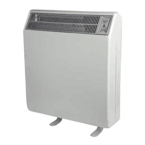
Dimplex Ultra-Slim Storage and Convector Heaters
Models CXL12N, CXL18N, CXL24N
Twin Sensor Models CXLS12N Automatic,
CXLS18N Automatic, CXLS24N Automatic
IMPORTANT
These instructions should be read carefully and retained for future reference.
Note also the information given on the appliance.
This heater is VERY HEAVY. In order to maintain stability
and to ensure its future safety in use, it is essential that the
heater is FIXED SOUNDLY TO A WALL and that the feet
are mounted on a FIRM, LEVEL SURFACE. Care should
be taken to avoid irregular surfaces, such as may result
from tiled surrounds partially protruding under the heater.
It is important that the following instructions are strictly
followed.
IT IS IMPORTANT THAT THE FIXING DEVICE CHOSEN IS
APPROPRIATE TO THE WALL MATERIAL TO WHICH THE
HEATER IS BEING FIXED. SOME MODERN INTERNAL
BUILDING MATERIALS ARE VERY LOW DENSITY BLOCK
AND REQUIRE SPECIALISED FIXING DEVICES TO PROVIDE
A SAFE, SECURE INSTALLATION.
THE HEATER MUST BE INSTALLED WHERE IT IS IMPOSSIBLE
FOR SWITCHES AND OTHER CONTROLS TO BE TOUCHED BY
A PERSON USING A BATH OR SHOWER.
Connection to a 30 amp Ring Circuit
The storage heater section of the CXLN/CXLSN
should not be connected to a 30 amp ring circuit.
A means for disconnection must be incorporated in
the fi xed wiring in accordance with the wiring rules.
The convector section may be connected to a 30 amp
ring circuit by either of the following methods.
IMPORTANT - Due to the newness of materials the heater will produce a slight smell for the fi rst few days of operation.
ROOMS MUST BE WELL VENTILATED AND YOUNG CHILDREN, CAGED BIRDS, OR PERSONS WITH RESPIRATORY
COMPLAINTS MUST NOT REMAIN IN CLOSE PROXIMITY TO THE HEATER DURING THE COMMISSIONING PERIOD.
To commission the heater set both controls to maximum and leave for 48 hours, after this period the controls should be
adjusted for everyday use - see operating instructions.
This appliance is not intended for use by persons (including children) with reduced physical, sensory or mental capabilities,
or lack of experience and knowledge, unless they have been given supervision or instruction concerning use of the appliance
by a person responsible for their safety. Children should be supervised to ensure that the do not play with the appliance.
Bricks are in
packs of two.
The pack catalogue
number is XT 8300
This product complies with the European Safety Standards EN60335-2-30 and the European Standard Electromagnetic Compatibility (EMC) EN55014, EN60555-2 and EN60555-3.
CXL12/CXLS12N - 12kWh
8 Bricks (4 Packs)
These cover the essential requirements of EEC Directives 2006/95/EC and 2004/108/EC
Installation Instructions
The installation of this appliance should be carried out by
competent personnel and be in accordance with the current IEE
wiring regulations. For the assembly of the heater tools required
are a No. 2 pozidriver, an electrical screwdriver with a 4mm
wide blade and a 8mm AF open ended or box spanner. A small
mirror will aid insertion of the front panel retaining screws.
Only Heat Resisting Cable (min. rating T85) should be used.
DO NOT COVER OR OBSTRUCT the surfaces of the
appliance.
DO NOT INSTALL the heater immediately below a socket
outlet.
DO NOT POSITION under windows where curtains may contact
the heater. (See minimum clearances, stage 5).
DO NOT PLACE OBJECTS in contact with the heater.
If, during any reassembly of the heater, a part of the thermal
insulation shows damage or deterioration which may impair
safety, it should be replaced with an identical part.
(a) 13 amp fused connection unit with D.P. switch to
BS5733.
(b) 13A switched socket outlet and a 13 amp fused
safety plug to BS1363 (we recommend the
safety plug to be ASTA Certifi ed for complete
compliance to BS1363).
NOTE: The double pole switch must have a contact
separation of at least 3mm in all poles.
CXL18/CXLS18N - 18kWh
12 Bricks (6 Packs)
(85317 Iss. 12)
CXL24/CXLS24N - 24kWh
16 Bricks (8 Packs)
Advertisement

Related Manuals for Dimplex CXL12N


Summary of Contents for Dimplex CXL12N
- Page 1 Installation Instructions Dimplex Ultra-Slim Storage and Convector Heaters (85317 Iss. 12) Models CXL12N, CXL18N, CXL24N Twin Sensor Models CXLS12N Automatic, CXLS18N Automatic, CXLS24N Automatic IMPORTANT These instructions should be read carefully and retained for future reference. Note also the information given on the appliance.
-
Page 2: Assembly Of Heater
3. Secure feet to base of the heater using two Taptite screws (provided) 4. Loosen hexagon head front panel securing screws, by 1-2 turns using for each foot. (On modules CXL12N/CXLS12N it would be necessary to screwdriver through aperture in each end packaging piece. - Page 3 8. Having decided on the method of standing the heater on the fl oor the 7. Fitting directly on the fl oor. If the fl oor is carpeted then the carpet position of the wall bracket should be marked on the wall. may be slit and underlay cut away to allow the feet to rest fi...
- Page 4 13. At this point determine which side of the heater off peak and on peak 14. Secure the heater to wall fi xing bracket by replacing the two screws supplies are to be connected. If off peak supply is to be connected from and spacer bushes removed in step 11.
- Page 5 CXL24N/CXLS24N remove the element to right of centre, on the CXL18N/ coincident with the air slots in the base insulation slab. Push the bricks CXLS18N remove the central element and on the CXL12N/CXLS12N fi rmly to the back of the heater. Fit the top rear row of bricks, with the remove the left hand element.
- Page 6 25. Replace the element which had been removed by carefully passing the ends through the base insulation slots into the terminal blocks below. Position the insulator on the element end in contact with the terminal block ceramic as shown, and tighten the connection screws. At this point check 26.
- Page 7 Mauve Wire Both in Still in Circuit Still in Circuit Circuit (Upper Element) (Lower Element) 450W 450W 900W #CXL12N/CXLS12N 450W 1000W 1450W #CXL18N/CXLS18N 650W 1350W 2000W CXL24N/CXLS24N 31. Check that the damper mechanism within the heater functions freely, by rotating the left hand control knob. Check also that the right hand (input) #Note: if the heater is situated underneath a shelf or overhand up to 250mm knob rotates freely.
- Page 8 CXL12N/CXLS12N Charge Controller Mains Supply Terminal Block & Earth Terminal Site Connections Peak Circuit Diagram Peak Circuit Diagram SENSING SENSING STAT STAT CXL24N CXL12N & 18N CXLS24N CXLS12N & 18N STAT NEON NEON SWITCH SWITCH CUT-OUT CUT-OUT MAUVE MAUVE ELEMENT...