AMX NetLinx Master-Ethernet Card/Module NXC-ME260 Instruction Manual
Amx corporation nxc-me260 netlinx master-ethernet card/module instruction manual
Hide thumbs
Also See for NetLinx Master-Ethernet Card/Module NXC-ME260:
- Instruction manual (48 pages) ,
- Hardware reference manual (26 pages) ,
- Engineering drawing (1 page)
Table of Contents
Advertisement
Quick Links
Download this manual
See also:
Programming Manual
Advertisement
Table of Contents

Related Manuals for AMX NetLinx Master-Ethernet Card/Module NXC-ME260


Summary of Contents for AMX NetLinx Master-Ethernet Card/Module NXC-ME260
- Page 1 instruction manual NXC-ME260 NetLinx Master-Ethernet Card/Module N e t L i n x C e n t ra l C o n t r o l l e r s a n d C a r d s...
- Page 2 RMA number. AMX Corporation is not liable for any damages caused by its products or for the failure of its products to perform. This includes any lost profits, lost savings, incidental damages, or consequential damages. AMX Corporation is not liable for any claim made by a third party or by an AMX Dealer for a third party.
-
Page 3: Table Of Contents
Table of Contents Product Information ...1 Front and rear panel components ... 1 Specifications ... 2 Rear panel LEDs: ICSNet/ICSHub... 3 Rear panel LEDs: Ethernet ... 3 Installation and Wiring ...5 Setting the Program Port DIP Switch ... 5 Baud rate settings ... 5 Program Run Disable (PRD) mode... - Page 4 Table of Contents Communication and Firmware Update ... 19 Communicating with the Master via the Program Port... 19 Verifying the current version of NetLinx Master firmware ... 20 Setting the System Value... 21 Working with multiple NetLinx Masters ... 22 Changing the system value on the Modero panel...
- Page 5 Master Security Setup Procedures... 51 Setting the system security options for a NetLinx Master (Security Options Menu) ... 51 Adding a Group and assigning their access rights... 52 Modifying an existing Group’s access rights ... 53 Showing a list of authorized Groups ... 54 Deleting an existing Group...
- Page 6 Table of Contents Option 9 - Delete Group ... 82 Option 10 - Show List of Authorized Groups... 83 Option 11 - Set Telnet Timeout in seconds... 83 Option 12 - Display Telnet Timeout in seconds ... 83 Option 13 - Make changes permanent by saving to flash ... 83 Main Security Menu ...
-
Page 7: Product Information
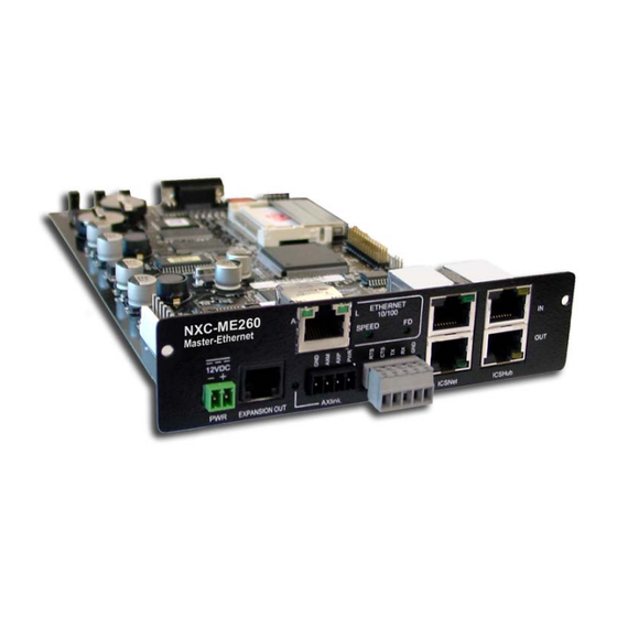
Product Information The NXC-ME260 (FG2010-60) is a Master-Ethernet Card for use within NetLinx systems. This card provides a 10/100 Base-T Ethernet connection and an RJ-11 SPE (Server Port Expander) connector for use with an AXB-SPE (Server Port Expander). The NXC-ME260 is the only Master card you will need, as it incorporates the functionality of all previous NetLinx Master Cards (NXC-M, NXC-ME, and NXC-MPE). -
Page 8: Specifications
Product Information Specifications NXC-ME260 Specifications Dimensions (HWD): NXC Card NXS Module Weight: Power Consumption: Memory: Microprocessor: Enclosure: Front Faceplate: Front Panel Components: Program port Status LED Output LED Input LED Front Panel LEDs - blink patterns Program Port DIP Switch Rear Panel Components: PWR connector EXPANSION OUT port... -
Page 9: Rear Panel Leds: Icsnet/Icshub
NXC-ME260 Specifications (Cont.) Rear Panel Components (Cont:) AXlink connector Axlink Status LED Program port ICSNet connectors ICSNet LEDs ICSHub In/Out connectors ICSHub IN/OUT LEDs Included Accessories: Optional Accessories: Rear panel LEDs: ICSNet/ICSHub ICSNet LED (green) lights to indicate data input activity on this port FIG. - Page 10 Product Information NXC-ME260 NetLinx Master-Ethernet Card/Module...
-
Page 11: Installation And Wiring
Installation and Wiring This section contains information about configuring the connector pinouts, and NXC-ME260 installation procedures. Setting the Program Port DIP Switch Prior to installing the NXC-ME260, configure the Program port’s communication speed by setting the baud rate DIP switch (SW1) to the appropriate setting. The Program port’s DIP switch is located to one side of the Master’s RS232 Program port. -
Page 12: Setting The Program Port Dip Switch
Installation and Wiring PRD mode prevents the NetLinx program stored in the Master from running when you power up the NXC-ME260. PRD mode should only be used when you suspect the resident NetLinx program is causing inadvertent communication and/or control problems. If necessary, place the Master in PRD mode and use the NetLinx Studio 2.1 program to resolve the communication and/or control problems with the resident NetLinx program. -
Page 13: Modes And Front Panel Led Blink Patterns
Modes and Front Panel LED Blink Patterns The following table lists the modes for the ME260 and blink patterns displayed on the front panel LEDs for each mode. These patterns are not evident until after the unit is powered. Modes and LED Blink Patterns Mode OS Start Boot... -
Page 14: Wiring Length Guidelines
Installation and Wiring Wiring length guidelines The Master requires a 12 VDC power from a PSN to operate properly. The unit should only have one source of incoming power. Using more than one source of power to the Master can result in damage to the internal components and a possible burn out. -
Page 15: Using The 4-Pin Mini-Phoenix Connector For Data With External Power
Using the 4-pin mini-Phoenix connector for data with external power To use the NetLinx 4-pin 3.5 mm mini-Phoenix (female) captive-wire connector for data communication and power transfer; the incoming PWR and GND cable from the PSN must be connected to the AXlink cable connector going to the NXC-ME260. FIG. 7 shows the wiring diagram. -
Page 16: Rs232 Program Port (Front Panel)
Installation and Wiring RS232 Program port (front panel) The following table shows the front panel RS232 (DB9) Program Port connector (male), pinouts, and signals. RS232 Program Port, Pinouts, and Signals Program Port Connector Male 5-Pin Program port (rear panel) The table below lists the pinouts and signals for the grey rear panel 5-pin 3.5 mm mini-Phoenix Program port connector. -
Page 17: Icshub Rj-45 Connections/Wiring
RJ-45 Pinout Information (EIA/TIA 568 B) Wire Color Orange/White Orange Green/White Blue White/Blue Green White/Brown Brown (female) RJ-45 connector - pin configurations Unlike the ICSNet ports, the ICSHub connections require a specific polarity. The IN/OUT configuration, on the Hub ports, was implemented to use the same cables as ICSNet, but these ports need TX and RX crossed. -
Page 18: Icshub Out Port
Installation and Wiring ICSHub OUT port The following table describes the pinout and signal information for the ICSHub OUT port. ICSHub OUT Pinouts and Signals Signal RX + RX - ------ ------ ------ ------ TX + TX - Ethernet 10/100 Base-T RJ-45 Connections/Wiring The following table lists the pinouts and signals associated to the Ethernet connector. -
Page 19: Ethernet Ports Used By The Me260
Ethernet ports used by the ME260 Ethernet Ports Used by the ME260 Port type Description ICSP Peer-to-peer protocol used for both Master-to-Master and Master-to-device communications. For maximum flexibility, the Master can be configured to utilize a different port than 1319, or disable ICSP over Ethernet completely from either Telnet or the Program Port located on the rear of the Master itself. -
Page 20: Spe Cable Pinout Information
FIG. 10 Daisy chaining two or more AXB-SPE's off of an NXC-ME260 SPE cable pinout information The following table gives pinout information for the RJ-11 SPE connector. AMX supplies a 6" RJ-11 cable with the AXB-SPE. The pins 2, 3, 4 and 5. Pin 2 is Ground; the others are all pin-to-pin connections. -
Page 21: Nxc-Me260 Installation And Mounting Procedures
NXC-ME260 Installation and Mounting Procedures Mounting the ME260 into an NXS-NMS 1. Confirm the contents of the shipment box to verify that you have all specified parts. Refer to the NXC-ME260 Specifications section on page 2 for more information about included and optional accessories. -
Page 22: Mounting The Nxc-Me260 In An Nxf Cardframe Or Nxi
Installation and Wiring Mounting the NXC-ME260 in an NXF CardFrame or NXI The NXC-ME260 can be installed in a NetLinx CardFrame (NXF) or NetLinx Integrated Controller (NXI). In both cases, the card mounts in a horizontal position, through the Master card slot on the rear panel of the enclosure. -
Page 23: Replacing The Lithium Batteries
Replacing the Lithium Batteries The NXC-ME260 is equipped with two lithium batteries (FG57-0013) that have a life of approximately 2.5 years to protect their memory. When DC power is on, the batteries (FIG. 15) are not used. When replacing the batteries, remove one at a time to avoid losing the program in memory. - Page 24 Installation and Wiring NXC-ME260 NetLinx Master-Ethernet Card/Module...
-
Page 25: Communication And Firmware Update
NetLinx Master via an IP section on page 28. Communicating with the Master via the Program Port 1. Launch NetLinx Studio 2.1 (default location is Start >Programs > AMX Control Disc > NetLinx Studio > NetLinx Studio 2.1). 2. Select Settings > Master Communication Settings, from the Main menu, to open the Master Communication Settings dialog (FIG. -
Page 26: Verifying The Current Version Of Netlinx Master Firmware
Communication and Firmware Update FIG. 16 Assigning Communication Settings and Baud Rates 7. Set the COM port parameters for the selected COM port being used for communication to the NetLinx Master. Default parameters are: COM1, 38400, 8 Data Bits, No Parity, 1 Stop Bit, and No Flow Control. -
Page 27: Setting The System Value
FIG. 17 Initial NetLinx Workspace window (showing the OnLine Tree tab) Setting the System Value 1. Access/open the Device Addressing dialog (FIG. 18) by either one of these two methods: Right-click on any System item listed in the OnLine Tree tab of the Workspace and select Device Addressing (from the pop-up list). -
Page 28: Working With Multiple Netlinx Masters
Communication and Firmware Update the Master to reboot. The STATUS and OUTPUT LEDs should begin to alternately blink during the incorporation. Wait until the STATUS LED is the only LED to blink. 7. Right-click the associated System number and select Refresh System to establish a new connection to the specified Master and refresh the System list with devices on that system. -
Page 29: Changing The Device Address On A Netlinx Device
If the Master does not appear in the Workspace window, check to make sure that the Master’s System Number (from within the Device Addressing tab) is correctly assigned. If there is a problem, use a system value of zero (0) on the Master. Changing the Device Address on a Netlinx Device 1. -
Page 30: Changing The Device Address On The Modero Panel
Communication and Firmware Update If the Master does not appear in the Workspace window, make sure that the Master’s System Number (from within the Device Addressing tab) is correctly assigned. If there is a problem, use a system value of zero (0) on the Master. Changing the device address on the Modero panel The device address on a Modero touch panel can not be changed from the Device Addressing dialog. -
Page 31: Resetting The Factory Default System And Device Values
Resetting the Factory Default System and Device Values 1. Access the Device Addressing dialog (FIG. 19 on page 23) by either one of these two methods: Right-click on any system device listed in the Workspace and select Device Addressing. Select Diagnostics > Device Addressing from the Main menu. 2. - Page 32 Communication and Firmware Update System Address reflects the value set in the Device Addressing tab Used to display the IP Address given to the Master from the DHCP Server FIG. 20 Network Addresses dialog (showing Get IP) DO NOT enter ANY IP information at this time, this step only gets the System Master to recognize that it should begin using an obtained DHCP Address.
-
Page 33: Assigning A Static Ip To The Netlinx Master
Assigning a Static IP to the NetLinx Master 1. Select Diagnostics > Network Addresses from the Main menu. 2. Verify the System number corresponds to the value previously assigned in the Device Addressing tab for the specific System Master. 3. Verify that zero (0) is entered into the Device field. The system value must correspond to the Device Address previously entered in the Device Addressing tab. -
Page 34: Communicating With The Netlinx Master Via An Ip
Network Addresses dialog to establish a new communication method to the Ethernet connected Master. 1. Launch NetLinx Studio 2.1 (default location is Start > Programs > AMX Control Disc > NetLinx Studio > NetLinx Studio 2.1). 2. Obtain the IP Address of the Master from your System Administrator, if you do not have an IP Address: Follow the steps outlined in either the Obtaining the Master’s IP Address (using... -
Page 35: Installing New Netlinx Master Firmware Via An Ip
11. Select Tools > Reboot the Master Controller to access the Reboot the Master dialog, then click Continue to reboot the Master and incorporate any changes. Allow 20 - 30 seconds for the Master to reboot. The STATUS and OUTPUT LEDs should begin to alternately blink during the incorporation. - Page 36 Communication and Firmware Update 4. If the firmware version is not build 139 (v2_XX_139) for the NXC-ME260; locate the latest firmware file from www.amx.com > Tech Center > Downloadable Files > Firmware Files > NetLinx Masters. 5. Verify you have downloaded the latest Master firmware (KIT) file to a known location.
- Page 37 12. Repeat steps 8 - 11 again (the last component will successfully be installed). 13. Click Close once the download process is complete. The OUTPUT and INPUT LEDs alternately blink to indicate the Master is incorporating the new firmware. Allow the Master 20 - 30 seconds to reboot and incorporate the new firmware.
- Page 38 Communication and Firmware Update NXC-ME260 NetLinx Master-Ethernet Card/Module...
-
Page 39: Netlinx Security And Web Server
The new NetLinx Web Server used to power the Master security and SSL certificate features on AMX Masters, not only provides user name/password security for the target Master, but also a new level of secure encryption through the use of a unique server certificate. -
Page 40: New Master Firmware Security Features
NetLinx Security and Web Server When using Mozilla on a Linux machine, the Group Rights column checkboxes (from within the Modify User page) can become greyed-out but are actually present. New Master Firmware Security Features Master Security Telnet Security Terminal (RS232 Program port) security HTTP (Web Server) Security FTP Security SSL Certificate Encryption and Identification Technology... -
Page 41: Accessing The Netlinx Master Via An Ip Address
Refer to the Installing New NetLinx Master Firmware via an IP section on page 29 for more detailed information on how to download the latest firmware (build 139) from www.amx.com. This firmware build enables SSL security and disables the ability to alter the Master security properties via a TELNET session. -
Page 42: Default Security Configuration
NetLinx Security and Web Server G3 panel pages accessed through the WebControl tab are virtual pages created by a user in TPDesign3 and then downloaded to the target Master. Interaction with these pages are not reflected on an actual G3 panel unless you use specific programming commands that link these virtual pages with their real G3 panel counterparts. -
Page 43: Security Tab
The NetLinx user account is created to be compatible with previous NetLinx Master firmware versions. This account is initially created by default and can later be deleted or modified. The administrator group account cannot be deleted or modified. The FTP Security and Admin Change Password Security are always enabled and cannot be disabled. -
Page 44: Security Tab - Enable Security Page
NetLinx Security and Web Server Security Tab Features (Cont.) SSL Certificate section Security tab - Enable Security page It is recommended that enabling the Master Security option be done after the groups, users, and passwords have been setup. If not, when the user accesses the Master from within another session, the default administrator user names and password are used for access. -
Page 45: Security Tab - Add Group Page
Security System Features (Cont.) OK/Cancel You must first enable the Master Security selection and then click OK before altering any settings. Click OK again after making alterations to any of these features (such as Terminal, HTTP, and Telnet access) and save these changes to the target Master. Security tab - Add Group page The Groups >... -
Page 46: Security Tab - Modify Group Page
NetLinx Security and Web Server Add Group Entries (Cont.) OK/Cancel A User represents a single potential client of the NetLinx Master, while a Group represents a logical collection of users. Any properties possessed by groups (example: access rights, directory associations, etc.) are inherited by all the members of the group. Security tab - Modify Group page The Groups >... -
Page 47: Security Tab - Group Directory Associations Page
Modify Group Entries (Cont.) HTTP Access Telnet Access Security Config Access OK/Cancel/Delete Security tab - Group Directory Associations page The Groups > Directory Associations link allows an authorized user to view current directory associations assigned to the selected group, add paths for new directory associations, and delete any previously configured directory associations (FIG. - Page 48 NetLinx Security and Web Server Here are some examples of valid entries: Valid Directory Association Entries Path /user1 /user1/ /Room1/iWebControlPages/* By default, all accounts that enable HTTP Access are given a '/*' Directory Association if no other Directory Association has been assigned to the account. Group Directory Association Entries Feature Select New Group...
-
Page 49: Security Tab - Add User Page
Security tab - Add User page The Users > Add User link allows an authorized user to add a user account (FIG. 30) and then assign that user’s current access rights. FIG. 30 Security Tab - Add User Add User Entries Feature User ID (user name) Group... -
Page 50: Security Tab - Modify User Page
NetLinx Security and Web Server Security tab - Modify User page The Users > Modify User link allows an authorized user to select from a listing of available users (FIG. 31) and then modify the Master’s access rights for the selected user. FIG. -
Page 51: Security Tab - User Directory Associations Page
Modify User Entries (Cont.) Telnet Access Security Config Access Password/Confirm OK/Cancel/Delete Security tab - User Directory Associations page The Users > Directory Associations link allows an authorized user to view current directory associations assigned to the selected user, add paths for new directory associations, and delete any previously configured directory associations (FIG. - Page 52 NetLinx Security and Web Server A single '/' is sufficient to grant access to all files and directories in the user directory and it's subdirectory. The '/*' wildcard can also be added to enable access to all files. All entries should start with a '/'.
-
Page 53: Security Tab - Ssl Server Certificate Page
Security tab - SSL Server Certificate page A certificate is a cryptographically signed object that associates a public key and an identity. Certificates also include other information in extensions such as permissions and comments. A "CA" is short for Certification Authority and is an internal entity or trusted third party that issues, signs, revokes, and manages these digital certificates. - Page 54 NetLinx Security and Web Server Server Certificate Entries (Cont.) City/Location State/Province Country Name Action OK/Cancel/Delete If a certificate has been purchased from an external CA and then installed onto a specific Master, DO NOT regenerate the certificate or alter its properties (ex: bit length, city, etc.).
-
Page 55: Security Tab - Export Certificate Request Page
Security tab - Export Certificate Request page The SSL > Export Certificate Request link opens an Export Certificate Request field (FIG. 34) where an authorized user can copy the raw text from a generated Certificate request into their clipboard and then send it to the CA. FIG. -
Page 56: System Tab
NetLinx Security and Web Server System Tab Displays the firmware version and log information for the NetLinx Master (FIG. 36). FIG. 36 System Tab Show Devices Tab Displays the device values and firmware versions of devices connected to the current NetLinx Master System (FIG. -
Page 57: Master Security Setup Procedures
Master Security Setup Procedures Setting the system security options for a NetLinx Master (Security Options Menu) 1. Enter the URL/IP Address of the target Master into the Address/URL field within the web browser. Refer to the Accessing the NetLinx Master via an IP Address section on page 35 for more detailed instructions on using your web browser to access your Master. -
Page 58: Adding A Group And Assigning Their Access Rights
NetLinx Security and Web Server 6. Click on the checkbox next to SSL Enable to enable the use of SSL encryption and server certificate usage. Activating this feature requires the creation of a server certificate. Refer to the SSL Certificate Procedures section on page 61 for instructions on creating and requesting a server certificate for the target Master. -
Page 59: Modifying An Existing Group's Access Rights
4. Click on the checkbox next to the requested access rights desired for the selected group. Placing a check in these fields activates the access rights (Terminal/Admin Change/FTP/ HTTP/Telnet/Security Configuration). Refer to the Security tab - Add Group page section on page 39 for more detailed field descriptions. -
Page 60: Showing A List Of Authorized Groups
NetLinx Security and Web Server 5. Click OK to accept and save the changes made on this tab to the Master. Clicking Delete removes the selected group from the list of authorized groups on the Master. Clicking Cancel voids any changes made within this tab, disables the security configuration session, voids any changes made to the Master, and returns you to the empty Security tab. -
Page 61: Adding A Group Directory Association
Adding a Group directory association 1. Click on the Security tab. By default this tab is blank until a security option is selected from the left of the browser window. Refer to the Security tab - Group Directory Associations page section on page 41 for more detailed descriptions on the security configuration options. 2. -
Page 62: Confirming The New Directory Association
NetLinx Security and Web Server Not only can an administrator provide group access to a file or folder on the Master, but also to an Application tab displayed within the web browser (such as Show Devices or Network). To add an association to an Application tab, enter the association location (ex: /showdevices.asp) into the Adding Association field. -
Page 63: Adding A User And Configuring Their Access Rights
Adding a User and configuring their access rights 1. Click on the Security tab. By default this tab is blank until a security option is selected from the left of the browser window. Refer to the Security tab - Add User page section on page 43 for more detailed descriptions on the security configuration options. -
Page 64: Modifying An Existing User's Access Rights
NetLinx Security and Web Server Each selection simply toggles the security setting from enabled to disabled. Modifying an existing User’s access rights 1. Click on the Security tab. By default this tab is blank until a security option is selected from the left of the browser window. -
Page 65: Showing A List Of Authorized Users
6. Enter the same password for the user into both the Password and Confirm fields, if you want to change the password. Leaving this field blank retains the current or previous password. A user password is a valid character string (4 - 20 alpha-numeric characters) that is used to supplement the user name/ID in defining the potential client. -
Page 66: Adding A User Directory Association
NetLinx Security and Web Server Adding a User directory association 1. Click on the Security tab. By default this tab is blank until a security option is selected from the left of the browser window. Refer to the Security tab - User Directory Associations page section on page 45 for more detailed descriptions on the security configuration options. -
Page 67: Confirming The New Directory Association
Confirming the new directory association 1. Click on the Security tab. 2. Click the Directory Associations link. 3. From the Delete Association section of the User Directory Associations window, click the down arrow from the Select Association field to open a list of associations and confirm the new directory association has been assigned to the user. -
Page 68: Self-Generating A Ssl Server Certificate Request
NetLinx Security and Web Server Self-Generating a SSL Server Certificate Request 1. Click on the Security tab (FIG. 45). Refer to the Security tab - SSL Server Certificate page section on page 47 for more detailed descriptions on the security configuration options. 2. -
Page 69: Creating A Request For A Ssl Server Certificate
11. Choose Self Generate Certificate from the drop-down list. certificate is generated and installed into the Master in one step. 12. Click OK to save the new encrypted certificate information to the Master or click Cancel to void any changes made within this tab and exit without making changes to the target Master. ONLY use the Regenerate certificate option when you have Self Generated your own certificate. -
Page 70: Importing A Ca Certificate To The Master Over A Secure Ssl Connection
NetLinx Security and Web Server 10. Click the down arrow from the Action field to open a drop-down listing of available certificate generation options. 11. Choose Create Request from the drop-down list. 12. Click OK to accept the information entered into the above fields and generate a certificate file. Refer to the Security tab - Export Certificate Request page section on page 49. -
Page 71: Display Ssl Server Certificate Information
4. Click OK to enter the new encrypted certificate information and save it to the Master or click Cancel to void any changes made within this tab and exit without making changes to the target Master. Once a certificate has been purchased from an external CA and then installed onto a specific Master, DO NOT regenerate the certificate or alter its properties (example: bit length, city, etc.).If the purchased certificate is regenerated, it becomes invalid. -
Page 72: Common Steps For Requesting A Certificate From A Ca
NetLinx Security and Web Server This method of certificate generation is used to modify or recreate a previously existing certificate already on the Master. By default, if a certificate is already present on the target Master, the Display Certificate Action is selected and these fields are populated with information. EX: if the company has moved from Dallas to Houston, all of the information is reentered exactly except for the City. - Page 73 4. Enter the name of the server being used (this is the Master). The server name is the name as it shows up in the URL of the Master you are securing with this server certificate. For example, if the URL of the Master will be https://www.myNetLinxMaster.com/, then enter the server name as www.myNetLinx Master.com.
-
Page 74: Accessing An Ssl-Enabled Master Via An Ip Address
NetLinx Security and Web Server Accessing an SSL-Enabled Master via an IP Address 1. Enter the IP Address of the target Master (example: 198.198.99.99) into the web browser Address field. 2. Press the Enter key on your keyboard to begin the communication process between the target Master and your computer. - Page 75 6. The user is then presented with a Certificate Import Wizard that begins the process of adding the certificate (FIG. 47). FIG. 47 Certificate Import Wizard 7. Click Next to proceed with the certificate store process. FIG. 48 Certificate Import Wizard- storing the certificate 8.
-
Page 76: Using Your Netlinx Master To Control The G4 Panel
NetLinx Security and Web Server 18. The first tab displayed within your open browser window is WebControl. Using your NetLinx Master to control the G4 panel Refer to the specific panel instruction manual for detailed information on configuring and enabling WebControl. -
Page 77: Using Your Netlinx Master To Control The G3 Panel
FIG. 50 WebControl VNC installation and Password entry screens 8. Click Yes from the Security Alert popup window to agree to the installation of the G4 WebControl application on your computer. This application contains the necessary Active X and VNC client applications necessary to properly view and control the panel pages from your computer. -
Page 78: What To Do When A Certificate Expires
NetLinx Security and Web Server 2. Click on the Download Java Web Start > Download Java Web Start 1.4.2 link to begin the download of the application to your hard drive and follow the installation procedures recommended by the application. 3. -
Page 79: Netlinx Security With A Terminal Connection
NetLinx Security with a Terminal Connection NetLinx ME260 Masters (build 139) have built-in security capabilities. It will require a valid user name and password to access the NetLinx System’s Telnet, HTTP and FTP servers. The security capabilities are configured and applied via a Telnet connection or the NetLinx Master’s RS-232 terminal interface (the RS232 Program port). -
Page 80: Accessing The Security Configuration Options
NetLinx Security with a Terminal Connection 4. Enter any text into the Name field of the HyperTerminal Connection Description dialog window and click OK when done. 5. From the Connect Using field, click the down-arrow and select the COM port being used for communication by the target Master. -
Page 81: Option 1 - Set System Security Options For Netlinx Master (Security Options Menu)
Option 1 - Set system security options for NetLinx Master (Security Options Menu) Type 1 and <ENTER> display the Security Options Menu. The Security Options Menu sets the "global" options for the NetLinx Master. It is accessed by the Set Security system options of the Main Security Menu. This first thing that will happen is you will be asked one of two questions. -
Page 82: Option 2 - Display System Security Options For Netlinx Master
NetLinx Security with a Terminal Connection Changes made to the target Master from within the Terminal window are not reflected within the web browser, until the Master is rebooted and the web browser connection is refreshed. Any changes made to the Master, from within the web browser are instantly reflected within the Terminal session without the need to reboot. -
Page 83: Option 4 - Edit User
4. Enter a password for the new user. A password is a valid character string (4 - 20 alpha-numeric characters) to supplement the user name in defining the potential client. This string is also case sensitive. 5. The session then prompts you to verify the new password. Enter the password again, and press <ENTER>... - Page 84 NetLinx Security with a Terminal Connection The Edit User Menu options are described in the following table: Edit User Menu Command 1) Change User Password 2) Change Inherits From Group 3) Add Directory Association 4) Delete Directory Association This selection will display any current Directory Associations 5) List Directory Associations This selection will display any current Directory Associations 6) Change Access Rights 7) Display User Record Contents This selection will display the group the user is assigned to and the...
-
Page 85: Option 5 - Delete User
Access Rights Menu Command 1) Terminal (RS232) Access (Enable/Disable) 2) Admin Change Password Access (Enable/Disable) 3) FTP Access (Enable/Disable) 4) HTTP Access (Enable/Disable) 5) Telnet Access (Enable/Disable) 6) Security Configuration Access (Enable/Disable) Option 5 - Delete user 1. Type <ENTER> to delete an existing user account. - Page 86 NetLinx Security with a Terminal Connection 2. Enter a name for the group. A group name is a valid character string (4 - 20 alpha-numeric characters) defining the group. This string is case sensitive, and each group name must be unique.
- Page 87 access to a file or directory. From the answer, it will enter the appropriate Directory Association. The NetLinx Master will not create the path if it is not valid. That must be done via another means, most commonly by using an FTP client and connecting to the FTP server on the NetLinx Master.
-
Page 88: Option 8 - Edit Group
NetLinx Security with a Terminal Connection Edit Group menu: Display Access Rights 1. At the Edit Group prompt, type 5 to view the current access rights for the selected group account. A sample session response is: Terminal (RS232)...Disabled Admin Password Change...Disabled FTP...Disabled HTTP...Disabled Telnet...Disabled... -
Page 89: Option 10 - Show List Of Authorized Groups
Option 10 - Show List of Authorized Groups 1. Type 10 and <ENTER> at the Security Setup prompt (at the bottom of the Main Security Menu) to display a list of all authorized group accounts. A sample session response is: The following groups are currently enrolled: administrator Group 1... -
Page 90: Main Security Menu
NetLinx Security with a Terminal Connection Main Security Menu The Main Security menu is described below: Main Security Menu Command 1) Set system security options for NetLinx Master 2) Display system security options for NetLinx Master 3) Add user 4) Edit user 5) Delete user 6) Show the list of authorized users 7) Add group... -
Page 91: Default Security Configuration
Main Security Menu (Cont.) Command 14) Reset Database 15) Display Database Default Security Configuration By default, the NetLinx Master will create the following accounts, access rights, directory associations, and security options. Account 1: Password: Group: Rights: Directory Association: /* Account 2: Password: Group: Rights:... -
Page 92: Help Menu
NetLinx Security with a Terminal Connection Help menu Type help at the prompt in the Telnet session to display the following help topics: Help Menu Options Command ----- Help ----- <D:P:S> ? or Help DATE DEVICE HOLDOFF ON|OFF DEVICE STATUS <D:P:S> DNS LIST <D:P:S>... -
Page 93: Logging Into A Session
ENABLE:DISABLED Logging Into a Session Until Telnet security is enabled, a session will begin with a welcome banner. Welcome to NetLinx v2.10.80 Copyright AMX Corp. 1999-2004 > The welcome banner is not displayed for Terminal sessions. When Terminal security is enabled, the user will be prompted for a user name and password before they will be allowed to access any commands available from Telnet. -
Page 94: Logout
After the password is entered, if the password is correct you will see a welcome banner as shown below: Login: User1 Password: ***** Welcome to NetLinx v2.10.80 Copyright AMX Corp. 1999-2002 > If the password is incorrect, the following will be displayed: Login: User1 Password: ***** Login not authorized. -
Page 95: Programming
Programming The NetLinx programming language allows numbers in the range 0-32,767. Device 0 refers to the Master Card; numbers greater than 32,767 are reserved for internal use only. The NetLinx programming language requires a Device:Port:System (D:P:S) syntax where Axcess expects only a device number. The NetLinx D:P:S triplet variable is expressed as: DEVICE:PORT:SYSTEM where: •... - Page 96 Displays status of the specified Master. Example (on a local Master): >DEVICE STATUS [0:1:0] Device 0 AMX Corp.,Master,v2.10.75 contains 1 Ports. Port 1 - Channels:256 Levels:8 MaxStringLen=64 Types=8 bit The following input channels are on:None...
- Page 97 Program Port Commands (Cont.) Command DISK FREE GET IP <D:P:S> MSG ON MSG OFF OFF <D:P:S, channel> ON <D:P:S, channel> NXC-ME260 NetLinx Master-Ethernet Card/Module Description Displays the total bytes of free space available on the Master Card's compact Flash memory. Example: >DISK FREE The disk has 2441216 bytes of free space.
- Page 98 >PROGRAM INFO -- Program Name Info -- Module Count = 1 Name is i!-PCLinkPowerPointTest -- File Names = 2 1 = C:\Program Files\AMX Applications\i!-PCLinkPowerPoint 2 = C:\Program Files\Common Files\AMXShare\AXIs\NetLinx.axi 2 = Name is MDLPP -- File Names = 2 1 C:\AppDev\i!-PCLink-PowerPoint\i!-PCLinkPowerPointMod.axs 2 C:\Program files\Common Files\AMXShare\AXIs\NetLinx.axi...
- Page 99 Enter DNS Entry 2 : 12.18.110.8 Enter DNS Entry 3 : 12.18.110.7 You have entered: Domain Name: amx.com DNS Entry 1: 192.168.20.5 DNS Entry 2: 12.18.110.8 DNS Entry 3: 12.18.110.7 Is this correct? Type Y or N and Enter -> Y Settings written.
- Page 100 Physical Address=NeuronID 000239712501 (00256)vxWorks Image (00001) (PID=0:OID=1) Serial=N/A (00256)BootROM (00001) (PID=0:OID=2) Serial=N/A (00256)AXLink I/F uContr(00001) (PID=0:OID=3) Serial=0000000000000000 00096 (00192)VOLUME 3 CONTROL BO(00001)AMX Corp. (PID=0:OID=0) Serial=0000000000000000 Physical Address=Axlink 00128 (00188)COLOR LCD TOUCH PAN(00001)AMX Corp. (PID=0:OID=0) Serial=0000000000000000 Physical Address=Axlink 05001 (00257)NXI Download (00001)AMX Corp.
- Page 101 Program Port Commands (Cont.) Command SHOW LOG SHOW NOTIFY NXC-ME260 NetLinx Master-Ethernet Card/Module Description Displays the log of messages stored in the Master's memory. The Master logs all internal messages and keeps the most recent messages. The log contains:· • Entries starting with first specified or most recent •...
- Page 102 Physical Address=NeuronID 000239712501 (00256)vxWorks Image (00001) (PID=0:OID=1) Serial=N/A (00256)BootROM (00001) (PID=0:OID=2) Serial=N/A (00256)AXLink I/F uContr(00001) (PID=0:OID=3) Serial=0000000000000000 00096 (00192)VOLUME 3 CONTROL BO(00001)AMX Corp. (PID=0:OID=0) Serial=0000000000000000 Physical Address=Axlink 00128 (00188)COLOR LCD TOUCH PAN(00001)AMX Corp. (PID=0:OID=0) Serial=0000000000000000 Physical Address=Axlink 05001 (00257)NXI Download (00001)AMX Corp.
-
Page 103: Esc Pass Codes
Program Port Commands (Cont.) Command TCP LIST URL LIST <D:P:S> ESC Pass Codes There are 'escape' codes in the pass mode. These codes can switch the display mode or exit the pass mode. The following 'escape' codes are defined. ESC Pass Codes Command + + ESC ESC Exit Pass Mode... -
Page 104: Notes On Specific Telnet/Terminal Clients
Programming Notes on Specific Telnet/Terminal Clients Telnet and terminal clients will have different behaviors in some situations. This section states some of the known anomalies. Windows client programs Anomalies occur when using a windows client if you are not typing standard ASCII characters (i.e. using the keypad and the ALT key to enter decimal codes). - Page 105 Programming NXC-ME260 NetLinx Master-Ethernet Card/Module...
- Page 106 ATLANTA • BOSTON • CHICAGO • CLEVELAND • DALLAS • DENVER • INDIANAPOLIS • LOS ANGELES • MINNEAPOLIS • PHILADELPHIA • PHOENIX • PORTLAND • SPOKANE • TAMPA 3000 RESEARCH DRIVE, RICHARDSON, TX 75082 USA • 800.222.0193 • 469.624.8000 • 469-624-7153 fax • 800.932.6993 technical support • www.amx.com...