AMX NETLINX MASTER NXC-ME260 Instruction Manual
Master-ethernet card/module, central controllers and cards
Hide thumbs
Also See for NETLINX MASTER NXC-ME260:
- Instruction manual (106 pages) ,
- Hardware reference manual (26 pages) ,
- Engineering drawing (1 page)

Related Manuals for AMX NETLINX MASTER NXC-ME260


Summary of Contents for AMX NETLINX MASTER NXC-ME260
- Page 1 instruction manual NXC-ME260 NetLinx Master-Ethernet Card/Module N e t L i n x C e n t ra l C o n t r o l l e r s a n d C a r d s...
- Page 2 This warranty extends only to products purchased directly from AMX Corporation or an Authorized AMX Dealer. AMX Corporation is not liable for any damages caused by its products or for the failure of its products to perform. This includes any lost profits, lost savings, incidental damages, or consequential damages. AMX Corporation is not liable for any claim made by a third party or by an AMX Dealer for a third party.
-
Page 3: Table Of Contents
Table of Contents Product Information ...1 Front and rear panel components ... 1 Specifications ... 2 Ethernet ports used by the ME260... 3 Modes and front panel LED blink patterns ... 4 Rear panel LEDs: ICSNet/ICSHub... 4 Rear panel LEDs: Ethernet ... 5 Installation and Wiring ...7 Setting the Program Port DIP Switch ... - Page 4 Table of Contents NetLinx Security Features... 27 Security Terms Used in This Document... 27 User... 27 Group ... 27 User Name ... 28 Group Name... 28 Password ... 28 Access Rights ... 28 Directory Associations... 28 Initial Setup (via Telnet or Terminal Connection) ... 29 Getting connected ...
-
Page 5: Product Information
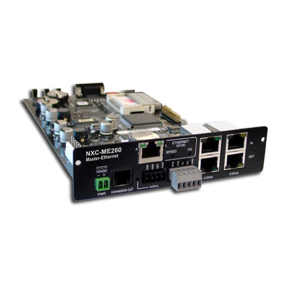
Product Information The NXC-ME260 Master-Ethernet Card is a Master Card for NetLinx systems with a 10/100BaseT TCP/IP Ethernet connection, and an RJ-11 SPE (Server Port Expander) connector for use with an AXB-SPE (Server Port Expander). The NXC-ME260 is the only Master Card you need, as it incorporates the functionality of all previous NetLinx Master Cards (NXC-M, NXC-ME, and NXC-MPE). -
Page 6: Specifications
Product Information Specifications NXM-ME260 Specifications Power consumption Memory Microprocessor Front Panel Components: Program port Status LED Output LED Input LED Front Panel LEDs - blink patterns Program Port DIP Switch Rear Panel Components: PWR connector EXPANSION OUT port Ethernet 10/100 port Ethernet 10/100 LEDs AXlink connector Axlink Status LED... -
Page 7: Ethernet Ports Used By The Me260
NXM-ME260 Specifications (Cont.) Rear Panel Components (Cont): ICSNet connectors ICSNet LEDs ICSHub In/Out connectors ICSHub IN/OUT LEDs Enclosure Front Faceplate Dimensions (HWD): Card(s) Module Weight Optional Accessories Ethernet ports used by the ME260 Ethernet Ports Used by the ME260 Port type Description ICSP Peer-to-peer protocol used for both master-to-master and master-to-device... -
Page 8: Modes And Front Panel Led Blink Patterns
Product Information Modes and front panel LED blink patterns The following table lists the modes for the Master Cards/Modules and blink patterns for the front panel LEDs for each mode. Modes and LED Blink Patterns Mode OS Start Boot Contacting DHCP server Unknown DHCP server... -
Page 9: Rear Panel Leds: Ethernet
Rear panel LEDs: Ethernet A - Activity LED (yellow) blinks when receiving Ethernet data packets. lights when transmitting data at 100 Mbps, and is off when transmitting at 10 Mbps. FIG. 3 Layout of Ethernet LEDs NXC-ME260 NetLinx Master-Ethernet Card/Module ETHERNET 10/100 SPEED... - Page 10 Product Information NXC-ME260 NetLinx Master-Ethernet Card/Module...
-
Page 11: Installation And Wiring
Installation and Wiring This section contains information about configuring the Modules and the ME260, wiring diagrams, and pinouts for assembling cables. Setting the Program Port DIP Switch Baud rate settings The Program Port DIP switch is located on the front of the Master Cards. For Modules, you must remove the front panel to access the DIP switch. -
Page 12: Setting The Program Port Dip Switch
Installation and Wiring DIP Switch positions 2,3 and 4 must remain in the OFF position at all times. Setting the Program Port DIP switch 1. Disconnect the power supply from the 2-pin PWR (green) connector on the Master Card. 2. Remove the front faceplate and four mounting screws from the Master Card's front panel. Then, locate the Program Port DIP switch (to the left of the Program port). -
Page 13: 5-Pin Program Port (Rear Panel)
5-Pin Program port (rear panel) The table below lists the pinouts and signals for the rear panel Program port connector. 5-Pin Program Port Pinouts and Signals Signal ICSNet RJ-45 Connections/Wiring The following table shows the pinouts, signals, and pairing information to use for ICSNet RJ-45 connections. -
Page 14: Icshub In Port
Installation and Wiring ICSHub IN port The following table describes the pinout/signal information for the ICSHub IN port. ICS Hub IN Pinouts and Signals Signal TX - TX + ------ ------ ------ ------ RX - RX + ICSHub OUT port The following table describes the pinout/signal information for the ICSHub OUT port. -
Page 15: Spe Port Connection/Wiring
FIG. 4 diagrams the RJ-45 cable and connectors. RJ-45 Plug FIG. 4 RJ-45 wiring diagram SPE Port Connection/Wiring Use an RJ-11 cable to connect the NXC-ME260 to an AXB-SPE Slave Port Expander. EXPANSION OUT port on the rear panel of the AXB-SPE (FIG. 5). FIG. -
Page 16: Spe Cable Pinout Information
FIG. 6 Daisy chaining two or more AXB-SPE's off of an NXC-ME260 SPE cable pinout information The following table gives pinout information for the RJ-11 SPE connector. AMX supplies a 6" RJ-11 cable with the AXB-SPE. connectors (on the AXB-SPE) use pins 2, 3, 4 and 5. Pin 2 is Ground; the others EXPANSION are all pin-to-pin connections. -
Page 17: Mounting The Modules Into An Equipment Rack
FIG. 7 diagrams the RJ-11 cable and connectors. RJ-11 Plug FIG. 7 RJ-11 wiring diagram Mounting the Modules Into an Equipment Rack To install the Modules into an equipment rack, you'll need an optional AC-RK Kit. 1. Remove the front panel from the Module to expose the mounting holes. 2. -
Page 18: Replacing The Lithium Batteries
Installation and Wiring To install a Master Card in either an NXF CardFrame or NXI Integrated Controller: 1. Discharge the static electricity from your body by touching a grounded object. 2. Unplug all the connectors from the Controller or Module. 3. -
Page 19: Programming
Programming The NetLinx programming language allows numbers in the range 0-32,767. Device 0 refers to the Master Card; numbers greater than 32,767 are reserved for internal use only. The NetLinx programming language requires a Device:Port:System (D:P:S) syntax where Axcess expects only a device number. The NetLinx D:P:S triplet variable is expressed as: DEVICE:PORT:SYSTEM where: •... - Page 20 Displays status of the specified Master. Example (on a local Master): >DEVICE STATUS [0:1:0] Device 0 AMX Corp.,Master,v2.10.75 contains 1 Ports. Port 1 - Channels:256 Levels:8 MaxStringLen=64 Types=8 bit The following input channels are on:None...
- Page 21 Program Port Commands (Cont.) Command DISK FREE GET IP <D:P:S> MSG ON MSG OFF OFF <D:P:S, channel> ON <D:P:S, channel> NXC-ME260 NetLinx Master-Ethernet Card/Module Description Displays the total bytes of free space available on the Master Card's com- pact Flash memory. Example: >DISK FREE The disk has 2441216 bytes of free space.
- Page 22 >PROGRAM INFO -- Program Name Info -- Module Count = 1 Name is i!-PCLinkPowerPointTest -- File Names = 2 1 = C:\Program Files\AMX Applications\i!-PCLinkPowerPoint 2 = C:\Program Files\Common Files\AMXShare\AXIs\NetLinx.axi 2 = Name is MDLPP -- File Names = 2 1 C:\AppDev\i!-PCLink-PowerPoint\i!-PCLinkPowerPointMod.axs 2 C:\Program files\Common Files\AMXShare\AXIs\NetLinx.axi...
- Page 23 Enter DNS Entry 2 : 12.18.110.8 Enter DNS Entry 3 : 12.18.110.7 You have entered: Domain Name: amx.com DNS Entry 1: 192.168.20.5 DNS Entry 2: 12.18.110.8 DNS Entry 3: 12.18.110.7 Is this correct? Type Y or N and Enter -> Y Settings written.
- Page 24 Physical Address=NeuronID 000239712501 (00256)vxWorks Image (00001) (PID=0:OID=1) Serial=N/A (00256)BootROM (00001) (PID=0:OID=2) Serial=N/A (00256)AXLink I/F uContr(00001) (PID=0:OID=3) Serial=0000000000000000 00096 (00192)VOLUME 3 CONTROL BO(00001)AMX Corp. (PID=0:OID=0) Serial=0000000000000000 Physical Address=Axlink 00128 (00188)COLOR LCD TOUCH PAN(00001)AMX Corp. (PID=0:OID=0) Serial=0000000000000000 Physical Address=Axlink 05001 (00257)NXI Download (00001)AMX Corp.
- Page 25 Program Port Commands (Cont.) Command SHOW LOG SHOW NOTIFY NXC-ME260 NetLinx Master-Ethernet Card/Module Description Displays the log of messages stored in the Master's memory. The Master logs all internal messages and keeps the most recent mes- sages. The log contains:· •...
- Page 26 Physical Address=NeuronID 000239712501 (00256)vxWorks Image (00001) (PID=0:OID=1) Serial=N/A (00256)BootROM (00001) (PID=0:OID=2) Serial=N/A (00256)AXLink I/F uContr(00001) (PID=0:OID=3) Serial=0000000000000000 00096 (00192)VOLUME 3 CONTROL BO(00001)AMX Corp. (PID=0:OID=0) Serial=0000000000000000 Physical Address=Axlink 00128 (00188)COLOR LCD TOUCH PAN(00001)AMX Corp. (PID=0:OID=0) Serial=0000000000000000 Physical Address=Axlink 05001 (00257)NXI Download (00001)AMX Corp.
-
Page 27: Esc Pass Codes
Program Port Commands (Cont.) Command TCP LIST URL LIST <D:P:S> ESC Pass Codes There are 'escape' codes in the pass mode. These codes can switch the display mode or exit the pass mode. The following 'escape' codes are defined. ESC Pass Codes Command + + ESC ESC Exit Pass Mode... -
Page 28: Notes On Specific Telnet/Terminal Clients
Programming Notes on Specific Telnet/Terminal Clients Telnet and terminal clients will have different behaviors in some situations. This section states some of the known anomalies. Windows client programs Anomalies occur when using a windows client if you are not typing standard ASCII characters (i.e. using the keypad and the ALT key to enter decimal codes). -
Page 29: Firmware Transfers
Controllers or System devices. NXI Master Controllers use Kit files for firmware upgrades. A Kit file (.KIT) is a package of several files, all of which are required to upgrade the firmware, and are available online via www.amx.com/firmware-files.asp. The Online Device Tree (Online Tree tab of the Workspace Window) displays information about each online device, including the current firmware version. - Page 30 Firmware Transfers 4. Review the File, Connection, Address, and Target Device information before you send. Check the Reboot option. Click the Send button to send the selected KIT file to the specified device. You can watch the progress of the transfer in the Send to NetLinx Device dialog. When the transfer is finished, and the reboot is complete, press the Close button.
-
Page 31: Netlinx Security
NetLinx Security NetLinx Masters (version 2.10.80 or later) have built-in security capabilities. It will require a valid user name and password to access the NetLinx System’s Telnet, HTTP and FTP servers. The security capabilities are configured and applied via a Telnet connection or the NetLinx Master’s RS-232 terminal interface (the DB9 Always use the Program port when entering potentially sensitive security information. -
Page 32: User Name
NetLinx Security User Name A user name is a valid character string (4 - 20 alpha-numeric characters) defining the user. This string is case sensitive. Each user name must be unique. Group Name A group name is a valid character string (4 - 20 alpha-numeric characters) defining the group. This string is case sensitive. -
Page 33: Initial Setup (Via Telnet Or Terminal Connection)
Master will not create the path if it is not valid. That must be done via another means, most commonly by using an FTP client and connecting to the FTP server on the NetLinx Master. Initial Setup (via Telnet or Terminal Connection) Security administration and configuration is done via either Telnet (the Ethernet Port on the NetLinx Master), or Terminal (the If you have NetLinx Studio installed, use the Tools >... -
Page 34: Set System Security Options For Netlinx Master (Security Options Menu)
NetLinx Security Or <ENTER> to return to previous menu Security Setup -> 3. The Main Security Menu shows a list of choices and a prompt. To select one of the listed choices, simply enter the number of the choice (1-13) at the prompt and press 4. -
Page 35: Display System Security Options For Netlinx Master
For example, if selection displayed again as follows: Select to change current security option 1) Terminal (RS232) Security... Enabled 2) HTTP Security... Disabled 3) Telnet Security... Enabled 4) Security Configuration Security... Enabled Or <ENTER> to return to previous menu Security Options -> Each selection simply toggles the security setting selected. -
Page 36: Add User
NetLinx Security 3) Add user 1. Type 3 and <ENTER> to create a new user account. A sample session response is: The following users are currently enrolled: administrator Fred Betty Enter user name: 2. At the Enter user name name is a valid character string (4 - 20 alpha-numeric characters) defining the user. This string is case sensitive. -
Page 37: Access Rights Menu
Or <ENTER> to return to previous menu Edit User -> Each selection (1-7) accesses the named option. Press return to the Main Security Menu. The Edit User Menu options are described in the following table: Edit User Menu Command 1) Change User Password 2) Change Inherits From Group 3) Add Directory Association 4) Delete Directory Association This selection will display any current Directory Associations... -
Page 38: Delete User
NetLinx Security Access Rights Menu Command 1) Terminal (RS232) Access (Enable/Disable) 2) Admin Change Password Access (Enable/Disable) 3) FTP Access (Enable/Disable) 4) HTTP Access (Enable/Disable) 5) Telnet Access (Enable/Disable) 6) Security Configuration Access (Enable/Disable) 5) Delete user 1. Type <ENTER> to delete an existing user account. -
Page 39: Edit Group Menu
Edit Group Menu Please select from the following options: 1) Add directory association 2) Delete directory association 3) List directory associations 4) Change Access rights 5) Display Access Rights Or <ENTER> to return to previous menu. Edit Group -> Edit Group Menu: Add directory association 1. -
Page 40: Edit Group Menu: Delete Directory Association
NetLinx Security Edit Group menu: Delete directory association 1. At the Edit Group prompt, type 2 to delete an existing directory association. A sample session response is: Select a directory association from the following: 1) /directory1/* 2) /directory2/* Select Directory -> 2. -
Page 41: Edit Group Menu: Display Access Rights
Edit Group menu: Display Access Rights 1. At the Edit Group prompt, type 5 to view the current access rights for the selected group account. A sample session response is: Terminal (RS232)...Disabled Admin Password Change...Disabled FTP...Disabled HTTP...Disabled Telnet...Disabled Security Configuration...Disabled Press <ENTER>... -
Page 42: Show List Of Authorized Groups
NetLinx Security 10) Show List of Authorized Groups 1. Type 10 and <ENTER> at the Security Setup prompt (at the bottom of the Main Security Menu) to display a list of all authorized group accounts. A sample session response is: The following groups are currently enrolled: administrator Group 1... -
Page 43: Main Security Menu
Main Security Menu The Main Security menu is described below: Main Security Menu Command 1) Set system security options for NetLinx Master 2) Display system security options for NetLinx Master 3) Add user 4) Edit user 5) Delete user 6) Show the list of authorized users 7) Add group 8) Edit group 9) Delete group... -
Page 44: Default Security Configuration
NetLinx Security Main Security Menu (Cont.) Command 14) Reset Database 15) Display Database Default Security Configuration By default, the NetLinx Master will create the following accounts, access rights, directory associations, and security options. Account 1: Password: Group: Rights: Directory Association: /* Account 2: Password: Group:... -
Page 45: Help Menu
Help menu Type help at the prompt in the Telnet session to display the following help topics: Help Menu Options Command ----- Help ----- <D:P:S> ? or Help DATE DEVICE HOLDOFF ON|OFF DEVICE STATUS <D:P:S> DNS LIST <D:P:S> DISK FREE GET DEVICE HOLDOFF GET IP <D:P:S>... -
Page 46: Logging Into A Session
URL LIST <D:P:S> Logging Into a Session Until Telnet security is enabled, a session will begin with a welcome banner. Welcome to NetLinx v2.10.80 Copyright AMX Corp. 1999-2002 > The welcome banner is not displayed for Terminal sessions. When Telnet security is enabled (or Terminal security for a terminal session), the user will be prompted for a user name and password before they will be allowed to access any commands available from Telnet. -
Page 47: Logout
After the password is entered, if the password is correct you will see a welcome banner as shown below: Login: User1 Password: ***** Welcome to NetLinx v2.10.80 Copyright AMX Corp. 1999-2002 > If the password is incorrect, the following will be displayed: Login: User1 Password: ***** Login not authorized. - Page 48 ATLANTA • BOSTON • CHICAGO • CLEVELAND • DALLAS • DENVER • INDIANAPOLIS • LOS ANGELES • MINNEAPOLIS • PHILADELPHIA • PHOENIX • PORTLAND • SPOKANE • TAMPA 3000 RESEARCH DRIVE, RICHARDSON, TX 75082 USA • 800.222.0913 • 469.624.8000 • 469-624-7153 fax • 800.932.6993 technical support • www.amx.com...