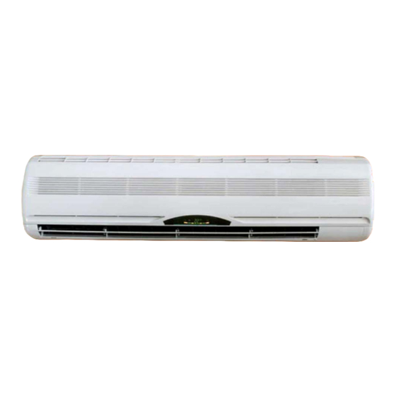
Summary of Contents for Ferroli 20-V
- Page 1 20-V - 30-V - 40-V Wall-mounted Fan coil °C INSTALLATION AND OPERATION MANUAL...
- Page 2 Dear customer, Thank you for having purchased a FERROLI air conditioner. It is the result of lengthy experience, dedicated planning research and has been made with top-quality materials and avant-garde technologies. Moreover, the CE marking gua- rantees that the appliance complies with the European Machine Directive governing safety matters. The quality level is constantly supervised, thus FERROLI products stand for Safety, Quality and Reliability.
-
Page 3: Table Of Contents
TABLE OF CONTENTS GENERAL SPECIFICATIONS ..............4 WHEN THE MACHINE ARRIVES . -
Page 4: General Specifications
GENERAL SPECIFICATIONS WHEN THE MACHINE ARRIVES As soon as the machine arrives, it is essential to check to make sure that all the materials listed in the shipping document have been consi- gned and that none of the parts has sustained damage due to trans- port. -
Page 5: Technical Specifications
(NOTE): the water pressure drops on the wet side are inclusive of los- - Inlet Water temperature 50°C, Δt water 5°C ses from the valve. - Ambient Air temperature 20°C D.B. OVERALL DIMENSIONS °C Mod. 20-V 30-V 40-V 1030 1030... -
Page 6: Safety Regulations
SAFETY REGULATIONS Strictly comply with the following regulations to prevent injuries to the operator or damage to the machine. · The machine must be installed in compliance with the laws in force in the country of use. · This installation manual, the operating instructions and the wiring diagrams are an integral part of the machine. They must be kept with care and be ready to hand for consultation when required. -
Page 7: Machine Installation
MACHINE INSTALLATION PACKING AND STORAGE Fig.1 All the models are provided with their own specific cardboard boxes. The units must be moved by hand. The box containing the unit gives instructions about how to handle the machine cor- rectly when it is stored and installed. The machine must be stored at a temperature between -25°C and 55°C. -
Page 8: Wiring Diagrams
NOTE: Refer to the wiring diagrams supplied with the machine for all work involving the electrical system. Models 30-V / 40-V Model 20-V FCP 30-V / 40-V FAN MOTOR... - Page 9 MACHINE INSTALLATION Model 20-V Fig.1 PIPE Models 30-V / 40-V 1025 PIPE The plastic casing of the unit has pre-cut holes which can be removed if necessary, so as to route the cooling pipes and cables. Fig.2 Proceed as described below: 1.
-
Page 10: Other Positions For Installation
MACHINE INSTALLATION Fig.3 7. Raise and carefully turn the pipe sections required for connecting to the exte- rior unit and route them through the Ø 70 mm hole. 8. Route the condensation drain pipe through the same hole. Depending on per- sonal requirements, this pipe can also be routed in other directions, so long as it slopes sufficiently to allow the condensation to drain away properly. -
Page 11: Wet Connections
MACHINE INSTALLATION WET CONNECTIONS The unit has wet connections with threads as those listed in the table below and flat seals. Model Couplings 20-V 30-V 1/2” 40-V PIPE INSULATION 1.The insulation must cover both the water inlet and outlet pipes as illustrated. -
Page 12: Air Vent
MACHINE INSTALLATION AIR VENT 1.Connect the water inlet and outlet pipes and, power the unit and set it to the cooling mode, making sure that the valve opens. This allows water to start entering the coils. 2. Check to make sure that there are no leaks from the wet connections. If there are no leaks, open the air vent will now start to leave the coils. -
Page 13: Setting At Work
SETTING AT WORK USE OF THE REMOTE CONTROL The remote control has a set of keys and a display that shows all the functions activated along with the parameters the user and installer need to correctly operate the unit. The keys are: Infrared signal Trasmettitore dei transmitter... -
Page 14: Indicator "Led" Of The Indoor Unit
SETTING AT WORK INDICATOR “LED” OF THE INDOOR UNIT °C The following is a description of the meaning of the LEDS on the front part of the indoor unit as they come on: 1. HEATING MODE INDICATOR 4. TEMP INDICATOR Units run when setting temp is lower than the room tem- Display the room temp. -
Page 15: Timer Programming
TEMP/TIMER °C EMERGENCY KEY OF THE UNIT Model 20-V The ON/OFF emergency key is situated on the front of the unit. It allows the unit to be powered and/or switched off if the remote con- trol is faulty and operates in the following way:... -
Page 16: Routine Maintenance
ROUTINE MAINTENANCE Fig.1 HOW TO CLEAN THE FILTERS OF THE UNIT The air filter must be checked and cleaned periodically to ensure that the appliance operates correctly. Proceed as described below (Fig. 1): Standard filter 1. Remove the plug from the power socket. 2. - Page 17 The manufacturer declines all liability for inaccuracies in this manual when due to printing or typing errors.
- Page 18 Ferroli spa ¬ 37047 San Bonifacio (Verona) Italy ¬ Via Ritonda 78/A tel. +39.045.6139411 ¬ fax +39.045.6100933 ¬ www.ferroli.it...


