Sony SLT-A33 Service Manual
Interchangeable lens digital camera/zoom lens kit
Hide thumbs
Also See for SLT-A33:
- Instruction manual (203 pages) ,
- Service manual (62 pages) ,
- Function manual (7 pages)
Advertisement
Quick Links
SLT-A33/A33L/A33Y/A55/A55V/A55L/A55VL/
SERVICE MANUAL
Ver. 1.0 2010.08
SERVICE NOTE (Check the following note before the service.)
– ENGLISH –
1-1.
METHOD FOR REPLACING THE P.O.I.
1-2.
PRECAUTION ON REPLACING THE AM-022 BOARD
1-3.
METHOD FOR CHECKING THE AS SLIDER UNIT (863)
1-4.
METHOD FOR ADJUSTING THE TEBURE REVISE
1-5.
METHOD FOR REPLACING THE AS SLIDER B ASSY
1-6.
METHOD FOR REPLACING THE AS HOLDER ACTUATOR ASSY
1-7.
GPS RECEIVING CHECK (SLT-A55V/A55VL/A55VY)
– JAPANESE –
1-1.
P.O.I.の交換方法
1-2.
AM-022基板交換時の注意
1-3.
ASスライダーユニッ ト (863) チェック方法
1-4.
手ぶれリバイス調整方法
1-5.
ASスライダーB ASSYの交換方法
1-6.
ASアクチュエータホルダASSYの交換方法
1-7.
GPS 受信確認 (SLT-A55V/A55VL/A55VY)
[About the service of this model]
SLT-A33L/A55L/A55VL is a commodity that packed the Interchangeable Lens Digital Camera (SLT-A33/A55/A55V) and Zoom Lens Kit (DT 18-
55mm F3.5-5.6 SAM).
SLT-A33Y/A55VY is a commodity that packed the Interchangeable Lens Digital Camera (SLT-A33/A55V) and W Zoom Lens Kit (DT 18-55mm
F3.5-5.6 SAM/DT 55-200mm F4-5.6 SAM).
Refer to each following service manual of the Zoom lens kit, when you repair.
• Zoom Lens Kit
SAL1855 (DT 3.5-5.6/18-55 SAM) (DT 18-55mm F3.5-5.6 SAM) Service Manual (9-852-691-1[])
SAL55200-2 (DT 4-5.6/55-200 SAM) (DT 55-200mm F4-5.6 SAM) Service Manual (9-852-692-1[])
INTERCHANGEABLE LENS DIGITAL CAMERA/ZOOM LENS KIT
The components identified
Les composants identifiés par
by mark 0 or dotted line with
une marque 0 sont critiques
mark 0 are critical for safety.
pour la sécurité.
Replace only with part number
Ne les remplacer que par une
specified.
pièce portant le numéro spécifié.
SLT-A33/A33L/A33Y/A55/A55V/A55L/A55VL/A55VY_L2
9-834-515-31
A55VY
Canadian Model
AEP Model
Australian Model
Chinese Model
Korea Model
Japanese Model
Tourist Model
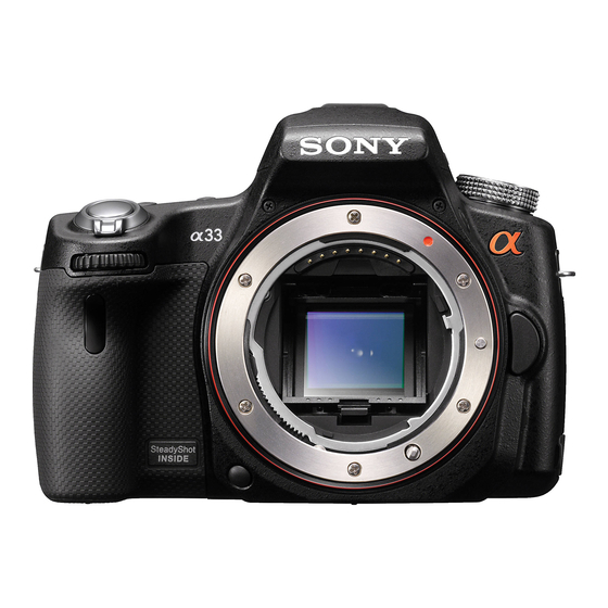
Photo: SLT-A55V
Ver.
Date
2
LEVEL
1.0
2010.08
Official Release
US Model
UK Model
E Model
Sony Corporation
Revision History
History
Contents
—
983451531.pdf
S.M. Rev.
issued
—
2010H29-1
© 2010.08
Published by Sony Techno Create Corporation
Advertisement

Related Manuals for Sony SLT-A33


Summary of Contents for Sony SLT-A33
- Page 1 SLT-A33L/A55L/A55VL is a commodity that packed the Interchangeable Lens Digital Camera (SLT-A33/A55/A55V) and Zoom Lens Kit (DT 18- 55mm F3.5-5.6 SAM). SLT-A33Y/A55VY is a commodity that packed the Interchangeable Lens Digital Camera (SLT-A33/A55V) and W Zoom Lens Kit (DT 18-55mm F3.5-5.6 SAM/DT 55-200mm F4-5.6 SAM).
- Page 2 1 152 000 Dolby Digital 2ch sensor equipped with Dolby 63 95 32mm Frame coverage Maximum dimensions 100% SLT-A33 Digital Stereo Creator 100% Approx. 63 × 95 × 32 mm SLT-A33 23.4 × 15.6 mm (APS-C 1.10 50mm • Manufactured under (2 1/2 ×...
- Page 3 Model information table Model SLT-A33 SLT-A33L SLT-A33Y SLT-A55 US, AEP, UK, E, AUS, US, CND, AEP, UK, E, CND, AEP, UK, E, AUS, Destination KR, J AUS, CH, KR, J, JE CH, KR, J Imager sensor × × × ×...
-
Page 4: Plastic Parts
DIAGRAMMES SCHÉMATIQUES ET LA LISTE DES PIÈCES SONT ARE CRITICAL TO SAFE OPERATION. REPLACE THESE COMPO- CRITIQUES POUR LA SÉCURITÉ DE FONCTIONNEMENT. NE REM- NENTS WITH SONY PARTS WHOSE PART NUMBERS APPEAR AS PLACER CES COMPOSANTS QUE PAR DES PIÈCES SONY DONT サービス,点検時には次のことにご注意ください。... -
Page 5: Service Note
USB Serial No. The set is shipped with a unique ID (USB Serial No.) written in it. This ID has not been written in a new board for service, and therefore it must be entered after the board replacement. SLT-A33/A33L/A33Y/A55/A55V/A55L/A55VL/A55VY_L2... - Page 6 It can be done easily if B is removed beforehand. (5) Remove the AS Unit Holder Ball. AS Slider B Assy AS Unit Holder Ball (11) Remove the three Ball Bearings. (6) Remove the two Ball Bearings. Ball Bearing Ball Bearing Ball Bearing SLT-A33/A33L/A33Y/A55/A55V/A55L/A55VL/A55VY_L2...
- Page 7 * After applying grease, attach the Ball Bearings. Ball Bearing G G-15 AS Holder Actuator Assy Ball Bearing G G-15 1-7. GPS RECEIVING CHECK (SLT-A55V/A55VL/A55VY) After a part of set was replaced or after the set was assembled, check the reception of GPS signal. SLT-A33/A33L/A33Y/A55/A55V/A55L/A55VL/A55VY_L2...
- Page 8 ASスライダー B Assy又はASアクチュエータホルダAssyを交換する前に,必ず以下の確認を行ってください。 (1) MBミラー枠ホルダ係止SPを押し,P.O.I.をアップしてくだ (1) P.O.I.を組み付ける際,下図のようにP.O.I.へこみ部が手前, さい。 下向きとなるように取り付けてください。 (1) CVリアカバー Assy ( 863) を取り外し,ASスライダーユニット (863) を仮付けします。 (2) ASスライダーユニット (863) を写真のように上向きにセットし,ボディを安定した場所に置きます。 (2) P.O.I.を奥へ押しながらツメ2箇所を取り外してください。 (3) 調整ソフトのSlider Unit Checkを行い,PITCH,YAW方向の動きを確認し,エラーが出た場合,PITCH,YAWの 動きに対応した部品に交換します。 1-2. AM-022基板交換時の注意 仕向けデータ 補修用基板と交換する時,補修用基板に書かれている仕向けデータは元の設定と異なっている場合があります。 USBシリアルNo. セットは,1台毎に異なる固有のID (USB Serial No.) を書き込んだ後,出荷されています。 新品の補修用基板には,このIDが書き込まれていないので,基板交換後にIDを入力する必要があります。 SLT-A33/A33L/A33Y/A55/A55V/A55L/A55VL/A55VY_L2...
- Page 9 (1) カメラのCVリアカバー Assy ( 863) を取り外し,ASスライダーユニット (863) にイメージャを組み付けた状態で仮付けして, ボディ,ASスライダーユニット (863) を立てた状態を保持します。 (9) ASスライダー A Assyを取り外します。 Aを先に取り外すと容易に取り外すことが出来ます。 (2) エナメル線の半田付け2箇所を取り外します。 (2) 調整ソフトのSlider Unit Checkを行い,調整結果がOKか確認します。 (3) フレキシブル基板をASスライダー B Assyから取り外します。 (3) 調整ソフトのTebure Revise Adjを行い,調整結果がOKか確認します。 (4) ASスライダーユニット (863) をセットに組み付けます。 (10) ASスライダー B Assyを取り外します。 Bを先に取り外すと容易に取り外すことが出来ます。 (4) ビス2本を取り外します。 (5) ASボールホルダを取り外します。 (11) ボールベアリング3個を取り外します。 (6) ボールベアリング2個を取り外します。 (7) キャップSP (Pitch,Yaw共に) を取り外します。 SLT-A33/A33L/A33Y/A55/A55V/A55L/A55VL/A55VY_L2...
- Page 10 – JAPANESE – 1-6. ASアクチュエータホルダASSYの交換方法 組み付け方 取り外し方 組み付け方 注意: ASアクチュエータホルダAssyを組み付けた後に作業を行ってください。 注意: ASスライダー B Assyを取り外した後に作業を行って 注意: ASスライダー B Assyを組み付ける前に作業を行って ください。 ください。 組み付け時は,取り外し手順の逆に行ってください。 下記指示部に,グリスを塗布してください。 (1) エナメル線の半田付けを取り外します。 組み付け時は,取り外し手順の逆に行ってください。 下記指示部に,グリスを塗布してください。 * グリスの塗布後,ボールベアリングを組み付けてください。 (2) フレキシブル基板をASアクチュエータホルダAssyの フックから取り外します。 (3) ビス4本を取り外し,ASアクチュエータホルダAssyを取り 外します。 * グリスの塗布後,ボールベアリングを組み付けてください。 1-7. GPS 受信確認 (SLT-A55V/A55VL/A55VY) 部品交換やセット組み立て後は,GPS 信号受信確認を行ってください。 SLT-A33/A33L/A33Y/A55/A55V/A55L/A55VL/A55VY_L2 1-6E...
-
Page 11: Repair Parts List
Follow the disassembly in the given numerical order. • -XX, -X mean standardized parts, so they may have some differences from the original one. The components identified by mark 0 or • Items marked “*” are not stocked since they are seldom required for routine service. Some delay dotted line with mark 0 are critical for safety. should be anticipated when ordering these items. Replace only with part number specified. • The mechanical parts with no reference number in the exploded views are not supplied. • Due to standardization, replacements in the parts list may be different from the parts specified Les composants identifiés par une marque Note: The procedure 5 is not necessary for SLT-A33/A33L/A33Y/A55/A55L. in the diagrams or the components used on the set. 0 sont critiques pour la sécurité. Ne les remplacer que par une pièce portant 4�Strobe Base Section 1�Rear Cover Section le numéro spécifié. [Disassembly] [Disassembly] [Exploded View] [Exploded View] •... -
Page 12: Note For Repair
1 kΩ /1 W (1-215-869-11). Wrap insulating tape fully around the leads of the resistor to prevent electrical shock. Wrap insulating tape. R:1 kΩ/1 W R:1 kΩ/1 W (Part code: 1-215-869-11) : 1-215-869-11) SUBSIDIARY MATERIALS G: Grease G-15 (J-6082-619-A) G-85 (J-6082-626-A) G-116 (J-6082-628-A) SLT-A33/A33L/A33Y/A55/A55V/A55L/A55VL/A55VY_L2... - Page 13 Part No. Description Ref. No. Part No. Description 4-192-214-01 CV RMC COVER 2-635-562-31 SCREW (M1.7) 4-194-534-01 CV SS COVER SHEET 3-080-204-21 SCREW, TAPPING, P2 4-192-215-01 VM EYE CUP #112 2-178-410-11 TITE (UB TITE) 1.4 4-154-680-01 CV DIOPTER ADJUST DIAL (857) SLT-A33/A33L/A33Y/A55/A55V/A55L/A55VL/A55VY_L2...
- Page 14 Ref. No. Part No. Description 1-489-077-11 SWITCH BLOCK, CONTROL (RS86300) 4-192-294-01 CV REAR GRIP 4-192-216-01 CV MODE DIAL PLATE (863) (SLT-A33/A33L/A33Y) 1-471-504-11 MAGNET (ND5X3.5X2.4-B) (Note1) 4-192-216-11 CV MODE DIAL PLATE (864) (SLT-A55/A55V/A55L/A55VL/A55VY) * 60 4-192-308-01 CV LCD HINGE SIDE COVER (G)
- Page 15 4-192-306-01 CV LCD HINGE COVER (M) LCD901 A-1789-529-A P CAB M BLOCK ASSY (SERVICE) 1-881-235-21 SHD-002 FLEXIBLE BOARD 2-635-562-31 SCREW (M1.7) A-1781-920-A PD-414 BOARD, COMPLETE 3-078-890-11 SCREW, TAPPING * 108 1-471-558-11 MAGNET (NEO44) (Note1) 4-192-309-01 EM LCD BOARD TAPE SLT-A33/A33L/A33Y/A55/A55V/A55L/A55VL/A55VY_L2...
- Page 16 CV DECORATION RING ∗ 156 4-192-225-01 CV SIDE COVER (L) X-2548-486-1 CV FRONT COVER ASSY (863) A-1782-153-A GP864 ASSY (GP-028) (SLT-A55V/A55VL/A55VY) (SLT-A33/A33L/A33Y) (Note4) 4-143-883-11 LOGO EMBLEM (A) X-2548-490-1 CV FRONT COVER ASSY (864) (SLT-A55V/A55VL/A55VY) (Note4) SP901 1-858-462-11 LOUDSPEAKER (1.0CM) (Note1)
- Page 17 * 203 4-192-220-01 BD TOWER BAR * 208 4-194-533-01 BD AM RADIATOR SHEET * 204 4-197-652-02 BD AS CUSHION A-1789-527-A AM-022 (863) BOARD, COMPLETE (SERVICE) 3-080-204-21 SCREW, TAPPING, P2 (SLT-A33/A33L/A33Y) 2-599-475-11 SCREW (M1.7) A-1790-073-A AM-022 (864) BOARD, COMPLETE (SERVICE) (SLT-A55/A55V/A55L/A55VL/A55VY) SLT-A33/A33L/A33Y/A55/A55V/A55L/A55VL/A55VY_L2...
- Page 18 A-1773-801-A IM IMAGER UNIT 14M (including CP001 4-194-127-01 IM TAPE, SPACER FIXED (Note1) Peel off the released paper. (CMOS imager) and IS-077 complete board) (SLT-A33/A33L/A33Y) (Note1, 2, 3) 4-194-225-01 IM TAPE FPC GUIDE A-1790-017-A IM IMAGER UNIT 16M (including IC4501...
- Page 19 Ref. No. Part No. Description A-1782-917-A SLIDER UNIT (863 SERVICE), AS (Note1, 2) 2-599-475-11 SCREW (M1.7) 4-110-892-01 SPRING, ADJUSTMENT AO 2-689-328-01 SCREW, CCD BLAST ADJUSTMENT X-2548-677-1 AS HOLDER ACTUATOR ASSY (Note4) 2-695-356-11 BALL, BEARING X-2548-676-1 AS SLIDER B ASSY (Note3) SLT-A33/A33L/A33Y/A55/A55V/A55L/A55VL/A55VY_L2...
- Page 20 MIC902 1-542-757-61 MICROPHONE UNIT X-2548-484-1 ST STROBE BASE ASSY PL901 1-455-061-11 SOLENOID, PLUNGER * 361 4-192-268-01 VM MODULE HOLDER 2-635-562-31 SCREW (M1.7) 1-881-219-21 AO-001 FLEXIBLE BOARD 3-078-890-11 SCREW, TAPPING X-2548-487-2 VM VF LENS ASSY 3-080-204-21 SCREW, TAPPING, P2 SLT-A33/A33L/A33Y/A55/A55V/A55L/A55VL/A55VY_L2 2-10...
- Page 21 * 407 4-195-077-01 BD LIGHT INTERCEPTION SHEET (A) 2-693-420-01 SP, S ADJUSTMENT * 404 4-162-330-01 EM FPC TAPE 2-635-562-31 SCREW (M1.7) A-1735-179-A ALX-8630 (including AF-131 flexible complete board) 3-080-204-21 SCREW, TAPPING, P2 (Note2) #207 4-191-605-01 S ADJUSTMENT SCREW SLT-A33/A33L/A33Y/A55/A55V/A55L/A55VL/A55VY_L2 2-11...
- Page 22 BD BT LID COVER OPEN SP 0 C901 1-116-522-11 ELECT 180uF 99% 330V * 458 4-192-241-01 BD BATTERY LOCK SHAFT X-2548-483-1 BD BT LID COVER ASSY 3-080-204-21 SCREW, TAPPING, P2 4-192-240-02 BD BATTERY LOCK * 461 4-192-242-01 BD BATTERY LOCK SP SLT-A33/A33L/A33Y/A55/A55V/A55L/A55VL/A55VY_L2 2-12...
- Page 23 SCREW, TAPPING, P2 #163 2-695-575-11 SCREW (T2), +P1 PAN TAPPNG 2-689-313-01 ROLLER A (SV), RING #164 3-268-954-11 SCREW, AF BASE PLATE STOPPER * 512 4-141-103-01 AF COUPLER TENSION SP #165 2-695-434-31 SCREW (T1.7), HEAD PAN TAPPING 4-141-108-01 AF COUPLER SLT-A33/A33L/A33Y/A55/A55V/A55L/A55VL/A55VY_L2 2-13...
- Page 24 EM A MOUNT LUG PLATE (LOWER) A-1779-677-A BL CONTACT UNIT (including BL-035 flexible board) (including M903 (charge motor) and SLK-008 flexible complete board) X-2548-413-2 MB MIRROR FRAME HOLDER ASSY (Note1) 3-080-204-11 SCREW, TAPPING, P2 A-1789-528-A P.O.I. (SERVICE) (Note1, 2) SLT-A33/A33L/A33Y/A55/A55V/A55L/A55VL/A55VY_L2 2-14...
- Page 25 ∗ 4-187-045-21 (FRENCH, ITALIAN) ∗ 4-187-045-31 (SPANISH, PORTUGUESE) ∗ 4-187-045-41 (GERMAN, DUTCH) ∗ 4-187-045-52 (TRADITIONAL CHINESE, SIMPLIFIED CHINESE) (E, JE) ∗ 4-187-045-62 (RUSSIAN) ∗ 4-187-045-72 (ARABIC, PERSIAN) 4-187-045-82 (KOREAN) 4-187-045-92 (SIMPLIFIED CHINESE) (CH) ∗ 4-187-046-11 (POLISH) ∗ 4-207-057-11 (INDONESIAN) SLT-A33/A33L/A33Y/A55/A55V/A55L/A55VL/A55VY_L2 2-15E...
- Page 26 Adhesive tape 1-9. Wrap the LCD-021 Flexible Board around the CV LCD Hinge Assy by rotating it one circle as shown in figure. CV LCD Hinge Cover (M) Adhesive tape 1-6. Attach the LCD-021 Flexible Board as shown in figure. SLT-A33/A33L/A33Y/A55/A55V/A55L/A55VL/A55VY_L2...
- Page 27 CV Front Cover Assy 7-2. Loosen the S Adjustment Screw for half circle. ALX-8630 (AF Module) Assembly-3: Routing of Flash Unit Harness Assembly-5: BD Absorber putting position BD Absorber BD Battery Holder Assy 7-3. Perform the adjustment. ST-233 Complete Board SLT-A33/A33L/A33Y/A55/A55V/A55L/A55VL/A55VY_L2...
- Page 28 G G-85 Ring Roller Shaft (C) (SV) AP Ring Roller C Iris Ring Ring Roller Shaft (C) (SV) EM A Mount Lug Plate (Lower) Boss Soldering 1-5. AP Aperture Unit Free Position Setting The AP Aperture Unit returns to the original potion when the Iris Joint Gear is removed from it. SLT-A33/A33L/A33Y/A55/A55V/A55L/A55VL/A55VY_L2...
- Page 29 MB AF/MF Change Lever are in AF position. MB Mount Spacer H Mount CV Front Cover Assy Focus Mode Switch MB AF/MF Change Lever ∗ Tighten the six screws in order of the number. #163: M2.0 X 5.5 (Tapping) (Silver) 2-695-575-11 SLT-A33/A33L/A33Y/A55/A55V/A55L/A55VL/A55VY_L2...
- Page 30 Mirror Lock Lever <Cleaning Procedure for Tip of CCD Cleaning Jig> 1. Put the two cleaning cloths on a tray like below. <ATTENTION> 1 Souse the one cleaning cloth in ethyl alcohol. If you cannot remove dirt with remedy above, cleaning by the following jig are used. 2 Put the other cleaning cloth on a tray as it is dry. Soak a small amount of EE3310 (Liquid cleaner) after wrapping the cleaning cloth (J-6082-636-A) around the cleaning jig (J-6082-635-A). 2. Dab the tip of CCD cleaning jig at the cleaning cloth of 1 5 or 6 times. * Do not slide the tip from right to left or up and down while dabbing. 3. Dab the tip of CCD cleaning jig at the cleaning cloth of 2 5 or 6 times. Cleaning Cloth * Do not slide from right to left or up and down while dabbing. (J-6082-636-A) 4. Wait until the tip will be dried completely. EE3310 1 Souse the cleaning Cleaning Jig cloth in ethyl alcohol. (J-6082-635-A) 2 The dry cleaning cloth. SLT-A33/A33L/A33Y/A55/A55V/A55L/A55VL/A55VY_L2 3-5E...