Advertisement
Quick Links
Download this manual
See also:
Owner's Manual
M M o o d d e e l l 1 1 3 3 0 0 X X V V
I I n n s s t t a a l l l l a a t t i i o o n n G G u u i i d d e e
© 2005 Directed Electronics, Vista, CA N561V 07-05
Advertisement

Related Manuals for Viper 130XV


Summary of Contents for Viper 130XV
- Page 1 M M o o d d e e l l 1 1 3 3 0 0 X X V V I I n n s s t t a a l l l l a a t t i i o o n n G G u u i i d d e e ©...
- Page 2 t t a a b b l l e e o o f f c c o o n n t t e e n n t t s s w w h h a a t t i i s s i i n n c c l l u u d d e e d d ..........3 3 b b y y p p a a s s s s i i n n g g G G M M v v e e h h i i c c l l e e a a n n t t i i - - t t h h e e f f t t s s y y s s t t e e m m s s ( ( V V A A T T S S ) ) .
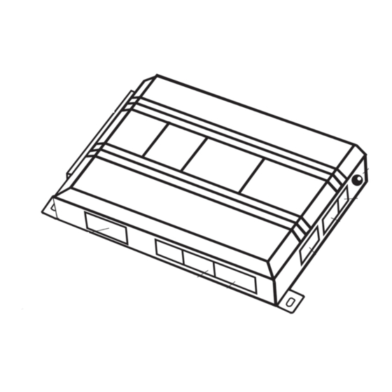
- Page 3 w w h h a a t t i i s s i i n n c c l l u u d d e e d d ■ T T h h e e c c o o n n t t r r o o l l m m o o d d u u l l e e ( ( s s e e e e d d i i a a g g r r a a m m ) ) ■...
- Page 4 w w a a r r n n i i n n g g ! ! s s a a f f e e t t y y f f i i r r s s t t The following safety warnings must be observed at all times: ■...
- Page 5 i i n n s s t t a a l l l l a a t t i i o o n n p p o o i i n n t t s s t t o o r r e e m m e e m m b b e e r r I I M M P P O O R R T T A A N N T T ! ! This product is designed for fuel-injected, automatic transmission vehicles only.
- Page 6 f f i i n n d d i i n n g g t t h h e e w w i i r r e e s s y y o o u u n n e e e e d d I I M M P P O O R R T T A A N N T T ! ! Do not use a 12V test light or logic probe (computer safe test light) to locate these wires! All testing described in this manual assumes the use of a digital multimeter.
- Page 7 is not in gear! If your meter reads (+)12V, go to the next step. If it doesn’t, probe another wire. 5. Cut the wire you suspect of being the starter wire. 6. Attempt to start the car. If the starter engages, reconnect it and go back to Step 3. If the starter does not turn over, you have the right wire.
- Page 8 f f i i n n d d i i n n g g a a ( ( + + ) ) p p a a r r k k i i n n g g l l i i g g h h t t w w i i r r e e Most vehicles use a (+) parking light circuit.
- Page 9 can use a fuel injector control wire for engine speed sensing. Common locations for a tachometer wire are the ignition coil itself, the back of the gauges, engine computers, and automatic transmission computers. I I M M P P O O R R T T A A N N T T ! ! Do not test tachometer wires using a test light or logic probe. The vehicle will be damaged.
- Page 10 p p r r i i m m a a r r y y h h a a r r n n e e s s s s ( ( H H 1 1 ) ) w w i i r r i i n n g g d d i i a a g g r r a a m m ______ H H 1 1 / / 1 1 L L I I G G H H T T G G R R E E E E N N / / B B L L A A C C K K...
- Page 11 h h e e a a v v y y g g a a u u g g e e r r e e l l a a y y w w i i r r i i n n g g d d i i a a g g r r a a m m ______ P P I I N N K K ( ( + + ) ) ( ( 3 3 0 0 A A M M P P ) ) O O U U T T P P U U T T T T O O I I G G N N I I T T I I O O N N C C I I R R C C U U I I T T...
- Page 12 p p r r i i m m a a r r y y h h a a r r n n e e s s s s ( ( H H 1 1 ) ) , , 9 9 - - p p i i n n c c o o n n n n e e c c t t o o r r H H 1 1 / / 1 1 L L I I G G H H T T G G R R E E E E N N / / B B L L A A C C K K ( ( - - ) ) f f a a c c t t o o r r y y a a l l a a r r m m d d i i s s a a r r m m This wire sends a negative pulse every time the remote start is activated or the doors are unlocked.
- Page 13 N N O O T T E E : : When the activation pulse count can be programmed to 1, 2, or 3 pulses when changed it will affect both activation inputs; the White/Blue wire and the remote control activation. H H 1 1 / / 5 5 G G R R A A Y Y / / B B L L A A C C K K ( ( - - ) ) d d i i e e s s e e l l w w a a i i t t - - t t o o - - s s t t a a r r t t b b u u l l b b i i n n p p u u t t Connect this wire to the wire in the vehicle that sends the signal to turn on the WAIT-TO-START bulb in the dash- board.
- Page 14 H H 1 1 / / 6 6 W W H H I I T T E E / / R R E E D D ( ( + + ) ) a a c c t t i i v v a a t t i i o o n n i i n n p p u u t t This input comes from the factory set to 2 activation pulses.
- Page 15 H H 1 1 / / 8 8 B B L L A A C C K K ( ( - - ) ) c c h h a a s s s s i i s s g g r r o o u u n n d d c c o o n n n n e e c c t t i i o o n n Remove any paint and connect this wire to bare metal, preferably with a factory bolt rather than your own screw.
- Page 16 ( ( - - ) ) L L i i g g h h t t F F l l a a s s h h O O u u t t p p u u t t h h e e a a v v y y g g a a u u g g e e r r e e l l a a y y i i n n t t e e r r f f a a c c e e The heavy gauge wires are used to energize high current circuits in the vehicle.
- Page 17 P P I I N N K K / / W W H H I I T T E E ( ( + + ) ) o o u u t t p p u u t t t t o o s s e e c c o o n n d d i i g g n n i i t t i i o o n n / / a a c c c c e e s s s s o o r r y y c c i i r r c c u u i i t t Connect this wire to the second ignition or accessory wire in the vehicle.
- Page 18 H H 2 2 / / 3 3 B B R R O O W W N N ( ( + + ) ) b b r r a a k k e e s s w w i i t t c c h h i i n n p p u u t t This wire MUST be connected to the vehicle's brake light wire.
- Page 19 has one side effect: If the customer inserts the key in the ignition with the driver's door open, the remote start system will shut down. If this interface is used, it is important to inform the customer that the driver’s door must be closed before inserting the key into the ignition when the remote start is active.
- Page 20 g g e e n n e e r r a a l l m m o o t t o o r r s s t t r r u u c c k k s s , , S S U U V V s s , , a a n n d d c c o o l l u u m m n n s s h h i i f f t t i i n n g g p p a a s s s s e e n n g g e e r r c c a a r r s s p p r r e e - - 1 1 9 9 9 9 6 6 d d o o d d g g e e d d a a k k o o t t a a p p i i c c k k u u p p s s w w i i t t h h 2 2 .
- Page 21 b b y y p p a a s s s s i i n n g g G G M M v v e e h h i i c c l l e e a a n n t t i i - - t t h h e e f f t t s s y y s s t t e e m m s s ( ( V V A A T T S S ) ) Vehicles with the GM VATS (Pass Key) systems have a resistor embedded in the ignition key.
- Page 22 1 1 9 9 9 9 5 5 a a n n d d n n e e w w e e r r v v e e h h i i c c l l e e a a n n t t i i - - t t h h e e f f t t s s y y s s t t e e m m s s ( ( i i m m m m o o b b i i l l i i z z e e r r s s ) ) 1995 and newer vehicle anti-theft systems (immobilizers) require a bypass module.
- Page 23 will excite the transponder, which is located (but not visible) in the head of the ignition key. The key transpon- der will then send a unique code back to the transceiver for evaluation. If the code matches a valid code of the system, the vehicle will be allowed to start.
- Page 24 p p r r o o g g r r a a m m m m i i n n g g j j u u m m p p e e r r s s l l i i g g h h t t f f l l a a s s h h ( ( + + ) ) / / ( ( - - ) ) This jumper is used to determine the light flash output polarity.
- Page 25 p p l l u u g g - - i i n n p p r r o o g g r r a a m m s s w w i i t t c c h h The Program switch plugs into the blue two-pin connector.
- Page 26 t t r r a a n n s s m m i i t t t t e e r r / / r r e e c c e e i i v v e e r r l l e e a a r r n n r r o o u u t t i i n n e e The system comes with one transmitter that has been taught to the receiver.
- Page 27 C C H H A A N N N N E E L L N N U U M M B B E E R R F F U U N N C C T T I I O O N N Auto-Learn* Lock/Unlock Channel 2 output...
- Page 28 t t a a c c h h l l e e a a r r n n i i n n g g t t o o l l e e a a r r n n t t h h e e t t a a c c h h s s i i g g n n a a l l Start the vehicle with the key.
- Page 29 T T r r a a n n s s m m i i t t . . The transmitter is used to select the desired setting. As shipped, the unit is con- figured to the LED ON settings. These are called the default settings. Pressing Channel One (usually Button I) will set it to the LED ON setting.
- Page 30 f f e e a a t t u u r r e e s s m m e e n n u u The factory default settings are indicated in b b o o l l d d text in the table below. F F E E A A T T U U R R E E D D E E F F A A U U L L T T - - L L E E D D O O N N S S E E T T T T I I N N G G L L E E D D O O F F F F S S E E T T T T I I N N G G...
- Page 31 f f e e a a t t u u r r e e d d e e s s c c r r i i p p t t i i o o n n s s The features of the system are described below. 1 1 E E N N G G I I N N E E C C H H E E C C K K —...
- Page 32 8 8 A A C C T T I I V V A A T T I I O O N N P P U U L L S S E E C C O O U U N N T T — — 1 1 /2/3 P P U U L L S S E E S S : : This feature allows the number of pulses to activate the remote start feature to be changed from 1, 2, or 3 pulses.
- Page 33 1 1 8 8 I I G G N N I I T T I I O O N N C C O O N N T T R R O O L L L L E E D D L L O O C C K K — — O O N N , , OFF: : When programmed ON the doors will lock when the key is on and all doors are closed.
- Page 34 L L E E D D S S H H U U T T D D O O W W N N F F L L A A S S H H E E S S M M O O D D E E System timed out Over-rev shutdown Three...
- Page 35 t t i i m m e e r r m m o o d d e e By pressing the remote buttons simultaneously the parking lights will flash 4 times and then start the vehicle and run for the set duration. The remote start can be shut off by the transmitter by press- ing the remote start button and remain in timer mode, but if any other shut down zones or the ignition becomes active the timer mode will cancel.
- Page 36 a. Make sure the hood is closed and no other shutdown circuits are active. b. Set the emergency brake. c. Turn the ignition key to the run position but do not start the engine. d. Put the vehicle in Drive (D). e.
- Page 37 ■ T T h h e e c c l l i i m m a a t t e e c c o o n n t t r r o o l l s s y y s s t t e e m m d d o o e e s s n n o o t t w w o o r r k k w w h h i i l l e e t t h h e e u u n n i i t t i i s s o o p p e e r r a a t t i i n n g g t t h h e e v v e e h h i i c c l l e e . . Either the wrong accessory wire is being energized or more than one ignition or accessory wire must be ener- gized in order to operate the climate control system.
- Page 38 ■ T T h h e e v v e e h h i i c c l l e e w w i i l l l l s s t t a a r r t t a a n n d d r r u u n n o o n n l l y y f f o o r r a a b b o o u u t t 1 1 0 0 s s e e c c o o n n d d s s . . 1.
- Page 39 w w i i r r i i n n g g q q u u i i c c k k r r e e f f e e r r e e n n c c e e g g u u i i d d e e 3 3 9 9 ©...