Table of Contents
Advertisement
Safe Operation Practices • Set-Up • Operation • Maintenance • Service • Troubleshooting • Warranty
O
'
M
peratOr
s
anual
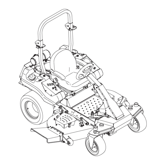
Tank SZ
WARNING
READ AND FOLLOW ALL SAFETY RULES AND INSTRUCTIONS IN THIS MANUAL
BEFORE ATTEMPTING TO OPERATE THIS MACHINE.
FAILURE TO COMPLY WITH THESE INSTRUCTIONS MAY RESULT IN PERSONAL INJURY.
CUB CADET LLC, P.O. BOX 361131 CLEVELAND, OHIO 44136-0019
Printed In USA
Form No. 769-07369
(February 23, 2012)
Advertisement
Table of Contents

Related Manuals for Cub Cadet Tank SZ


Summary of Contents for Cub Cadet Tank SZ
- Page 1 READ AND FOLLOW ALL SAFETY RULES AND INSTRUCTIONS IN THIS MANUAL BEFORE ATTEMPTING TO OPERATE THIS MACHINE. FAILURE TO COMPLY WITH THESE INSTRUCTIONS MAY RESULT IN PERSONAL INJURY. CUB CADET LLC, P.O. BOX 361131 CLEVELAND, OHIO 44136-0019 Printed In USA Form No. 769-07369...
-
Page 2: Table Of Contents
Visit us on the web at www.cubcadet.com See How-to Maintenance and Parts Installation Videos at www.cubcadet.com/tutorials ◊ Locate your nearest Cub Cadet Dealer at (877) 282-8684 ◊ Write to Cub Cadet LLC • P.O. Box 361131 • Cleveland, OH • 44136-0019... -
Page 3: Safe Operation Practices
Important Safe Operation Practices WARNING! This symbol points out important safety instructions which, if not followed, could endanger the personal safety and/or property of yourself and others. Read and follow all instructions in this manual before attempting to operate this machine. Failure to comply with these instructions may result in personal injury. - Page 4 Training Always wear appropriate clothing and personal protective equipment (e.g. safety glasses, long pants, gloves, hearing protection , safety shoes, hard hat) when operating or Read the Operator’s manual and other training material. If maintaining this machine. Long hair, loose fitting clothing the operator(s) or mechanic(s) cannot read English it is the or jewelry may get entangled in moving parts.
- Page 5 Never attempt to operate the machine without the Keep all movements on the slopes slow and gradual. Do mowing deck attached; the machine could tip over. not make sudden changes in speed or direction. Rapid acceleration could cause the front of the machine to lift Keep the machine and especially the engine exhaust and rapidly flip over backwards, which could cause serious system and hydraulic components clean and free of grease,...
- Page 6 Never allow children under 16 years of age to operate this Seat belts shall be used and shall be properly fastened machine. Children 16 and over should read and understand the about the operator’s waist at all times, except when the instructions and safe operation practices in this manual and on ROPS are: the machine and should be trained and supervised by an adult.
- Page 7 Hydraulic Devices and Systems Never remove fuel cap or add fuel while the engine is hot or running. Allow engine to cool at least two Hydraulic fluid escaping under pressure may have sufficient minutes before refueling. force to penetrate skin and cause serious injury. If foreign fluid is Never over fill fuel tank.
- Page 8 Do not modify engine Grass catcher components and the discharge cover are subject to wear and damage which could expose moving To avoid serious injury or death, do not modify engine in any parts or allow objects to be thrown. For safety protection, way.
-
Page 9: Safety Symbols
Safety Symbols This page depicts and describes safety symbols that may appear on this product. Read, understand, and follow all instructions on the machine before attempting to assemble and operate. Symbol Description READ THE OPERATOR’S MANUAL(S) Read, understand, and follow all instructions in the manual(s) before attempting to assemble and operate WARNING—... - Page 10 2 — S ection peration racticeS...
-
Page 11: Assembly & Set-Up
Assembly & Set-Up Contents of Crate • One Zero-Turn Tractor • One ROPS Assembly • One Steering Wheel • One Deck Wash Hose Coupler • One Zero-Turn Tractor Operator’s • One Engine Operator’s Manual Manual NOTE: All references in this manual to the left or right side and The two hydrostatic transmissions are equipped with a front or back of the machine are from the operating position bypass valve that will allow you to manually move the... - Page 12 Install Roll Over Protective System (ROPS) Install the upper ROPS section onto the lower ROPS “posts”. Install the bolts, retaining washers and lock nuts. See Fig. 3-4. The Roll Over Protective System (ROPS) has not been installed on your unit for shipping purposes. Using the hardware found in the Roll Over Protective System container, install it on your unit Retaining as follows:...
- Page 13 Move the upper ROPS section to the upright position, and Place the belleville washer over the steering wheel and insert the locking pins with their retainer hairpin clips. See secure with the hex lock screw. See Fig. 3-8. Fig. 3-6. Locking Pin Steering Wheel...
-
Page 14: Seat Adjustment
Seat Adjustment Suspension Seat (If equipped) This machine is equipped with an adjustable seat, which includes Standard Seat (If equipped) a retractable seat belt assembly and an Operator Presence Sensor (OPS). The OPS in the form of a switch, is integrated into This machine is equipped with an adjustable seat, which includes a retractable seat belt assembly and an Operator Presence the seat bottom and is connected to the machine electrical... - Page 15 The mechanical suspension mechanism incorporates weight/ ride adjustment controls for operators in the 125 to 275 lb. weight range (turn the knob on the front of the seat clockwise to increase the weight capacity and counter-clockwise to decrease. NOTE: The seat base must be secured by the latch, otherwise, the seat assembly could tilt forward.
-
Page 16: Controls & Features
Controls & Features Forward Drive Pedal Reverse Drive Pedal Deck Lift Pedal Steering Column Adjustment Lever Deck Height Index Deck Lift Release Lever Parking Break Lever Digital Tachometer & Hour Meter Tool Box Throttle Control Ignition Switch Choke Knob PTO Switch Accessory Switch Receptacles Cup Holder Fuel Gauge... -
Page 17: Throttle Control
Digital Tachometer and Hour Meter Forward Drive Pedal The forward drive pedal is located on the right side of the machine, along the running board. Press the forward drive pedal forward to cause the tractor to travel forward. Ground speed is also controlled with the forward drive pedal. - Page 18 Deck Height Index Fuel Gauge There is a fuel gauge on top of each of the two fuel tanks and measures the fuel level in each tank. The deck height index consists of several holes located on the left of the foot platform. Each hole corresponds to a 1⁄4” change in the deck height position ranging from 1”...
-
Page 19: Operation
It has been prepared to help you ever malfunction, do not operate the machine. Contact your operate and maintain your machine efficiently. authorized Cub Cadet Dealer. Fill the fuel tank with only clean, fresh, unleaded gasoline •... -
Page 20: Driving The Tractor
Practice Operation (Initial Use) the engine’s starter motor to cool. Try again after waiting. If after a few attempts the engine fails to start, do not keep Operating a zero-turn tractor is not like operating a conventional trying to start it with the choke closed as this will cause type riding tractor. - Page 21 Driving the Tractor Forward Driving the Tractor In Reverse WARNING! WARNING! Keep all movement of the drive pedals Always look behind and down on both slow and smooth. Abrupt movement of the pedals sides of the tractor before backing up. Always look can affect the stability of the tractor and could cause behind while traveling in the reverse direction.
- Page 22 Executing a Zero Turn Using the Mower Deck A zero turn maneuver can be executed while the machine WARNING! Make certain the area to be mowed is is moving in the forward or reverse directions if the free of debris, sticks, stones, wire or other objects steering wheel is turned completely in the one direction.
- Page 23 If a safety circuit is not working as designed, the lowest noise levels. Bahia blades are configured without offset, contact you Cub Cadet dealer to have the tractor inspected. DO and with a maximum amount of sharpened cutting edge.
- Page 24 Reconfigurable Mower Discharge Cutting Gauge Inner Baffle Baffle Blades Wheels Front Roller Rear Rollers Standard set-up Installed Installed Hi-lift Low = 3 to 5” Low = 3 to 5” Low = 3 to 5” High = 1 to High = 1 to High = 1 to Stems (Dandelion, Bahia, 2-1⁄2”...
-
Page 25: Maintenance & Adjustment
Maintenance & Adjustments Maintenance Schedule Before Every 25 Hours Every 50 Hours Every 500 Hours After Mowing Each use Check gasoline level Check hydraulic hoses for leaks Check tires & tire pressure Check deck, mower and hydro drive belts Check blades and blade bolt tightness Check safety switches for proper operation Check fluid level in transmission oil expansion reservoir Check engine intake screen/cover... - Page 26 OIL CHART Number of Oil Points Description DAILY Apply a few drops of SAE engine oil, grease, or use a spray lubricant. Apply Deck Suspension Pivots the oil to both sides of pivot points. Wipe Height Adjustment Turnbuckle Clevis Pin off any excess.
- Page 27 If a safety circuit is not working as designed, contact you Cub Cadet dealer to have the tractor inspected. DO Maintain oil level as instructed in engine manual. Be careful not NOT operate the tractor if any safety circuit is not functioning to spill oil on any of the belts.
- Page 28 Battery Leaking Tires When a flat tire occurs, repair or replace immediately. The normal CALIFORNIA PROPOSITION 65 WARNING procedure is to remove the wheel and replace it. If a tire is Battery posts, terminals, and related accessories getting soft, park the mower on the nearest level, paved area. contain lead and lead compounds, chemicals known to the State of California to cause cancer and Rear Tire...
- Page 29 Deck Wash System Tractor Storage WARNING! When using the deck wash system, never If your tractor is not going to be operated for an extended period engage the deck from any position other than the of time (thirty days to approximately six months), the tractor operator’s seat of the tractor.
- Page 30 Leveling the Mower Deck Sharpen the blades so that the mower will be ready to use when needed. When correctly adjusted the mower deck should be level side to Protect the metal surfaces. Repair scratches with the side, and the front of the deck should be approximately 1⁄4” lower appropriate touch-up spray paint.
- Page 31 Front to Back Leveling Adjusting the Belt Tension Measure the blade-to-ground height at the right rear blade To increase the tension on the belt, loosen the jam nuts on the tip. Again be sure to measure at the blade tip at the rear of deck rods, then tighten the flange nuts until a ten-pound pull with the right blade when aligned along the mower centerline.
- Page 32 Remove the flange lock nut and carriage bolt securing Adjust the cable housing nuts one full turn and check the front deck wheel and spacer to the deck. Remove the parking capacity. Repeat if parking brake does not hold. wheel and carriage bolt. Refer to Fig. 6-5. See Fig.
-
Page 33: Service
If you have a recurring problem with blown fuses, have the tractor’s negative battery lead to the negative battery post (marked electrical system checked by your Cub Cadet Service Dealer. NEG). Move the cable away from the negative battery post. -
Page 34: Deck Removal
Deck Removal CAUTION: There is a certain amount of spring tension due to the weight of the deck. When removing the lift Remove the mower deck from the tractor as follows: linkage from the deck the tension of the springs will go from the deck to the deck lift pedal. - Page 35 WARNING! Route the PTO belt as shown in Fig. 7-5. After routing the Avoid pinching injuries. Never place belt around the PTO pulley, use a 1⁄2” drive in the idler pulley your fingers on the idler spring or between the belt bracket and turn towards the right of the tractor to finish and a pulley while removing the belt.
- Page 36 Sharpening the Blades Use a 1-1⁄8” socket wrench on the pulley side of the spindle bolt. See Fig. 7-7. Set the parking brake. Clean any debris from the blades. Keep blades sharp and free of build up at all times. Hex Screw To properly sharpen the cutting blades, remove equal amounts of metal from both ends of the blades along the...
- Page 37 Several components must be removed and special tools used in order to change the tractor’s transmission drive belt. See your Cub Cadet dealer to have the transmission drive belt replaced. Tractor Creeping Creeping is the slight forward or backward movement of the mower when the throttle is on and the speed control pedals are in the neutral position.
-
Page 38: Troubleshooting
Troubleshooting Problem Cause Remedy Excessive vibration 1. Cutting blade loose or unbalanced. 1. Tighten blade and spindle. 2. Damaged or bent cutting blade. 2. Replace blade. Uneven cut 1. Deck not leveled properly. 1. Perform side-to-side deck adjustment. 2. Dull blade. 2. -
Page 39: Replacement Parts
Replacement Parts Component Part Number and Description 759-3336 Spark Plug KH-25-083-01-S Primary Air Filter (SZ-48 & SZ-60 w/ Kohler) KH-25-083-04-S Safety Air Filter (SZ-48 & SZ-60 w/ Kohler) Air Filter (SZ-60 w/ Kawasaki) KH-24-050-13-S Fuel Filter (SZ-48) KH-25-050-22-S Fuel Filter (SZ-60 w/ Kohler) Fuel Filter (SZ-60 w/ Kawasaki) KH-12-050-01-S Oil Filter (SZ-48 &... - Page 40 Component Part Number and Description 634-3159 Deck Wheel 925-1707D Battery 951-12193 Gas Cap 746-04534 Throttle Control 746-04812 Choke Control 725-05000 Ignition Key 01006693 Discharge Chute Assembly 02002666 Wheel Assembly (SZ-48), 23 x 9.50-12 634-04734 Wheel Assembly (SZ-60), 24 x 12-12 634-04704 Wheel Assembly, 15 x 6.5-8 10 —...
-
Page 41: Attachments & Accessories
Attachments & Accessories Part No. Part 59A30033150 Power Assist Triple Bagger 59A30036150 72” Snow Blade 59A30035150 Electric Deck Lift 490-850-0005 Blade Removal Tool 490-850-0008 Oil Siphon... - Page 42 FEDERAL and/or CALIFORNIA EMISSION CONTROL WARRANTY STATEMENT YOUR WARRANTY RIGHTS AND OBLIGATIONS MTD Consumer Group Inc, the United States Environmental Protection Agency (EPA), and, for those products certified for sale in the state of California, the California Air Resources Board (CARB) are pleased to explain the emission (evaporative and/or exhaust) control system (ECS) warranty on your outdoor 2006 and later small off-road spark-ignited engine and equipment (outdoor equipment engine) In California, new outdoor equipment engines must be designed, built and equipped to meet the State’s stringent anti-smog standards (in other states, 1997 and later model year equipment must be designed, built, and equipped to meet the U.S.
- Page 43 WARRANTED PARTS: The repair or replacement of any warranted part otherwise eligible for warranty coverage may be excluded from such warranty coverage if MTD Consumer Group Inc demonstrates that the outdoor equipment engine has been abused, neglected, or improperly maintained, and that such abuse, neglect, or improper mainte- nance was the direct cause of the need for repair or replacement of the part.
- Page 44 361131, Cleveland, Ohio 44136-0019, call 1-877-282- 8684 required maintenance and service intervals. or log on to our website at www.cubcadet.com. The limited warranty set forth below is given by Cub Cadet LLC with In Canada: respect to new merchandise purchased or leased and used in the Contact MTD Products Limited, Kitchener, ON N2G 4J1, call 1-800- 668-1238 or log on to our website at www.mtdcanada.com.