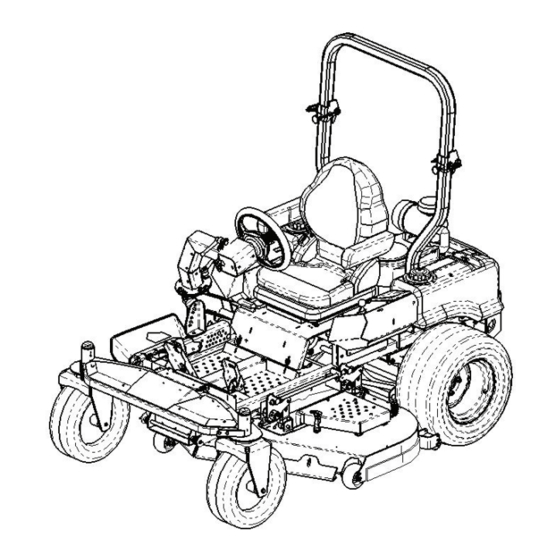
Cub Cadet THE TANK S6031 Operator's And Service Manual
Commercial zero-turn riding mower
Hide thumbs
Also See for THE TANK S6031:
- Brochure & specs (2 pages) ,
- Brochure (4 pages) ,
- Operator's manual (48 pages)

Related Manuals for Cub Cadet THE TANK S6031


Summary of Contents for Cub Cadet THE TANK S6031
- Page 1 Commercial Zero-Turn Riding Mower Professional Turf Equipment S6031 S7237 OPERATOR’S AND SERVICE MANUAL...
-
Page 2: Table Of Contents
Foreword ..............3 General Safety Operations . -
Page 3: Foreword
The Tank Hydrostatic Zero-Turn Synchro-Steer Commercial Riding Mower provides superb maneuver- ability, mid-mount cutting capability for professional landscapers, commercial lawn service companies, professional turf managers and golf course superintendents. The machine incorporates many safety fea- tures that should be studied by all operators and maintenance personnel before use. The list of safety precautions should receive particular attention. -
Page 4: General Safety Operations
OPERATIONS A. DANGER Do not operate machine in confined areas where exhaust gases can accumulate. Do not operate machine without mower chute deflec- tor in place and operational. Do not carry passengers. Do not operate nor store machine in areas where open flames, electrical switches and circuit breakers are present. -
Page 5: Related To Fuel
B. Related to Fuel Fuel is highly flammable and its vapors can explode if ignited. Please respect it. Do not smoke or permit others to smoke while han- dling fuel. Always use approved containers for fuel and fill slowly to decrease the chance of static electricity buildup and spillage. -
Page 6: Towing
operating the mower. 15. Never attempt to operate the traction unit without the mowing deck attached. 16. Keep the mower and especially the engine and hydraulic components clean and free of grease, grass and leaves to reduce the chance of fire and to permit proper cooling. -
Page 7: H.steering Control
fabric. An OPS in the form of a switch, is integrated into the seat bottom and is connected to the machine electrical system. The seat back is also covered with a heavy-duty vinyl fabric, it adjusts to recline up to 16 degrees, (lever actuated on opera- tor’s left side). -
Page 8: Safety Decals
SAFETY DECALS AND LABELS WARNING SHIELD MISSING DO NOT OPERATE Part Number: 00030635 Part Number: 01002166 Part Number: 777S33087 Part Number: 777S30503 Part Number: 777D12837 Part Number: 02005110 WARNIN Maximum weight on hitch is 50 lbs. Maximum towed load is 500 lbs. Never allow passengers on towed equipment. -
Page 9: Specifications
SPECIFICATIONS GENERAL INFO. Controls: Engine ignition and start switch; throttle; choke; speed control pedals; electric blade clutch switch; parking brake; mower deck lift Steering: 14” diameter steering wheel coupled to hydraulic steering valve and cylinder Parking Brake: Mechanical linkage brake to internal drum brakes Seat: Adjustable seat and armrests. -
Page 10: Operating Instructions
OPERATING INSTRUCTIONS Figure. 4 Engine throttle Ignition Switch Electric Blade Choke Lever Clutch Switch A.General When Mowing: Keep adults, children, and pets away from the area to be mowed. When operating this mower, in the forward direc- tion, do not allow the speed control pedals to rap- idly return to Neutral. -
Page 11: Controls
g. Slow-down before turning and come to a complete stop before any zero turn maneuver. h. Do not stop machine or park machine over com- bustible materials such as dry grass, leaves, debris, etc. To Mow Grass and Produce a Striped Pattern Pick a point on the opposite side of the area to be mowed (post, tree, shrub, etc.). -
Page 12: Initial Adjustments
mower deck removal and installation). The following features are incorporated into the hydraulic actuated valve implement lift design: Lever implement lift allows for some operators with physical limitations to use the implement lift mechanisms and the machine; reduces potential for operator fatigue; accommodates a variety of operator sizes, shapes, and strengths. -
Page 13: Zero Turn Break-In And Operating Procedures
of the deck on each side of the mower. (Four dimensions.) Note: The front edge of the mowing deck should be 1/8"-1/4" below the rear edge of the deck so that the blades are cutting grass in only the front half of their circular path. - Page 14 also referred to as blade control switch) is in the “off” (down) position. Move the choke control forward and the engine speed control (throttle) forward (half way). Note: E.F.I. Tanks do not have a choke control. Insert the ignition key, turn the switch toward the spring-loaded “Start”...
-
Page 15: Mower Cutting Blades
Make sure that the speed control pedal is in the neutral position. Turn the electric blade clutch switch “Off”. Push the throttle control to a position a third of the way between slow and fast. Insert the key in the ignition and start switch and turn the switch to “On”. -
Page 16: Maintenance And Service
Height of Cut Clevis Pin Figure. 9 MAINTENANCE AND SERVICE WARNING: Disconnect the spark plug wires or remove the key from the ignition to prevent the engine from acciden- tally starting before performing any maintenance on this mower. A. Mower Deck Removing the Mower Deck: Apply the parking brake. -
Page 17: Hydraulic Oil
To replace the blade reverse the above process and tighten nut to 100-120 lb ft. WARNING: Never mow with dull blades! Blades that are bent should be replaced! The cutting blades are sharp and can cause severe injury. Wrap the cutting surface of the blade with a rag to avoid injury. -
Page 18: Electrical System
d. Raise the seat forward to expose the hydraulic oil fill point. e. Clean the area around the hydraulic fill oil cap. Remove hydraulic fill oil cap. g. Place a suitable container (at least 1 gallon) under the hydraulic reservoir and filter. h. -
Page 19: Tires
Attach the end of the red jumper cable to the Pos- itive terminal (+) of the charged battery. b. Attach the other end of the red jumper cable to the Positive terminal (+) of the low charge bat- tery. Attach the end of the black jumper cable to the Negative terminal of the charged battery. -
Page 20: Brakes
Front Wheel—25 psi max; 20-25 psi recom- mended Cutting Deck Ball Wheels—Solid Polyurethane. Use the Following guidelines for maintaining the tires: Balance inflation pressure between the rear tires to help maintain straight travel (see tire side wall for proper inflation pressure). b. -
Page 21: Hydraulic System
Note: The pumps are not owner-repairable. If a pump fails, contact your Cub Cadet Commercial dealer. Do not disassemble the pump. Speed Control Adjustments: The speed control pedal incorporates a Return-To-Neutral (RTN) fea-... -
Page 22: Storage
tative for the procedure to reset the RTN mechanism on the hydrostatic pumps. If the hydrostatic pump RTN is adjusted, the control linkage must also be readjusted. G. Storage General: If your mower will not be in service for a few months, it should be stored in a dry location that is not subject to drastic changes in temperature. -
Page 23: Maintenance Schedule
MAINTENANCE SCHEDULE A. Daily Checks Before starting engine: Check the fuel level.** b. Check the engine oil level.** Check the hydraulic oil level. d. Check the hydraulic hoses for leaks, abrasion, kinks, twists, or a flattened condition. Check the tires and tire pressure. Drive Tires: 10-12 psi. -
Page 24: Lubrication Chart
OIL CHART Apply a few drops of engine oil or use a spray lubricant. Apply the oil to both sides of pivot points. Wipe off any excess. Start engine and operate mower briefly to insure that oil spreads evenly. Number of Oil Points Description DAILY Deck Suspension Pivots... -
Page 25: Performance Adjustments
Performance Adjustments A. Engine RPM Check and Adjustment Description High RPM Spec. 31 & 37 Kawasaki 3600 +/-50 NOTE: RPM Specs. are for free running engines under no load. Verify that the speed control pedals are in the neutral position, the parking brake is on, and the PTO drive is disengaged. -
Page 26: F.adjustable Front Skirt
lower the mowing deck into the 4" height of cut posi- tion. (The 4" height of cut position is recommended in order for one to see and obtain a measurement. Any height of cut position is acceptable as long as a proper measurement can be taken.) Check the right and left front tire pressure. -
Page 27: Wiring Diagram
WIRING DIAGRAM GD: 02002824... -
Page 28: Reconfigurable Mower
28 28... -
Page 29: Slope Gauge
SLOPE GAUGE... - Page 30 MTD Consumer Group Inc cannot deny warranty solely for the lack of receipts. As the lawn mower owner, you should however be aware that MTD Consumer Group Inc may deny you warranty coverage if your lawn mower or a part has failed due to abuse, neglect, or improper maintenance or unapproved modifications.
- Page 31 The repair or replacement of any warranted part otherwise eligible for warranty coverage may be excluded from such warranty coverage if MTD Consumer Group Inc demonstrates that the lawn mower has been abused, neglected, or improperly maintained, and that such abuse, neglect, or improper maintenance was the direct cause of the need for repair or replacement of the part.
- Page 32 The limited warranty set forth below is given by Cub Cadet LLC with respect to new merchandise used for commercial and related purposes...