Table of Contents
Advertisement
Owner's Manual
WARNING:
If the information in this manual is not followed exactly, a fire or explosion may
result causing property damage, personal injury or loss of life.
- Do not store or use gasoline or other flammable vapors and liquids in the vicinity of this or any
other appliance.
- WHAT TO DO IF YOU SMELL GAS
¥ Do not try to light any appliance.
¥ Do not touch any electrical switch; do not use any phone in your building.
¥ Immediately call gas supplier from a neighbor's phone. Follow the gas supplier's instructions.
¥ If you cannot reach your gas supplier, call the fire department.
- Installation and service must be performed by a qualified installer, service agency or the gas supplier.
Spirit - Gas Stove Room Heater
- July, 1994 -
10850 117th Place N.E. Kirkland, WA 98033
OMNI
Listed
Advertisement
Table of Contents
Troubleshooting

Related Manuals for Lopi Spirit


Summary of Contents for Lopi Spirit
-
Page 1: Introduction & Important Information
¥ Immediately call gas supplier from a neighbor's phone. Follow the gas supplier's instructions. ¥ If you cannot reach your gas supplier, call the fire department. - Installation and service must be performed by a qualified installer, service agency or the gas supplier. Spirit - Gas Stove Room Heater OMNI Listed... -
Page 2: Safety Precautions
AFETY RECAUTIONS ¥ IF YOU SMELL GAS: * Do not light any appliance * Extinguish any open flame * Do not touch any electrical switch or plug or unplug anything * Open windows and vacate building * Call gas supplier from neighbor's house, if not reached, call fire department ¥... - Page 3 AFETY RECAUTIONS ONTINUED ¥ Do not place clothing or ¥ Light the heater using the other flammable items on built-in piezo igniter. Do or near the heater. not use matches or any Because this heater can be other external device to controlled by a thermostat light your heater.
-
Page 4: Table Of Contents
ABLE OF ONTENTS General Information Introduction & Important Information ....................1 Safety Precautions..........................2 Features & Specifications ........................5 Stove Installation Heater Placement ..........................6 Floor Protection ........................... 7 Vent Requirements ..........................7 Gas Line Install ............................ 8 Finalizing the Installation ........................9 Operating Your Heater Reviewing the Installation ........................ -
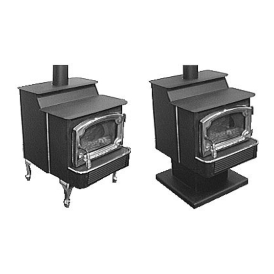
Page 5: Features & Specifications
With Cast Legs 30 7/8" With Black Legs 29 1/2" * Subtract 4" to reach the base of the flue collar **Use the Lopi pedestal, part # 99200 101 Vent Opening Diameter = 4" Weight = 205 Pounds Electrical Specifications: Blower Electrical Rating: 115 Volts, 1.3 Amps, 60 Hz (150 watts on high) -
Page 6: Stove Installation
TOVE NSTALLATION For qualified installers only! This appliance must be installed in accordance with all local codes, if any; if not, follow ANSI Z223.1 and the requirements listed in this manual. Failure to follow all of the requirements may result in property damage, bodily injury, or even death. Check with local building officials for any permits required for installation of this gas heater and notify your insurance company before hooking up this heater. -
Page 7: Floor Protection
.) - TOVE NSTALLATION For qualified installers only! Floor Protection When the stove is installed directly on carpeting, vinyl or other combustible material other than wood flooring, the stove must be installed on a metal or wood protection panel extending the full width and depth of the stove. -
Page 8: Gas Line Install
.) - TOVE NSTALLATION For qualified installers only! Vent Requirements (continued) ¥ Vent termination must have an approved cap (to prevent water from entering) ¥ Vent termination must not be located where it will become plugged by snow or other material ¥... -
Page 9: Finalizing The Installation
.) - TOVE NSTALLATION For qualified installers only! Gas Inlet Location: LOCATION OF THE GAS INLET CENTER: The 3/8" N.P.T. gas HEIGHT: inlet portrudes 1 1/2" From Base of Stove 1 1/2" from the back edge of With Pedestal 12 3/4" the stove. -
Page 10: Reviewing The Installation
EVIEWING THE NSTALLATION The check off list below details the installation concerns that you, the consumer, should know prior to starting the heater. This information is very important and must be checked off. There are no combustible items placed within 36" of the front of the heater or swing within 36"... -
Page 11: Before You Begin
PERATING EATER Before You Begin READ THIS ENTIRE MANUAL BEFORE YOU USE YOUR NEW HEATER. FAILURE TO FOLLOW THE INSTRUCTIONS MAY RESULT IN PROPERTY DAMAGE, BODILY INJURY, OR EVEN DEATH. Before starting your heater make sure you have read the section titled Safety Precautions. Any questions should be referred to your dealer. -
Page 12: Starting The Pilot
PERATING EATER ONTINUED Starting The Pilot Flame The pilot flame is required to ignite the main burners (it also plays a safety role). It should be left on once lit. It will stay lit unless the gas control valve is turned to "OFF". However, the pilot will go out if the gas is shut off or if the heater malfunctions. -
Page 13: Running Your Heater
PERATING EATER ONTINUED Starting the Heater for the First Time ¥ Paint Curing insures a durable finish. Start the heater and burn on low for 20 minutes. Turn off and let cool. Repeat twice to fully cure the paint. Fumes and smoke from the paint curing and oil burning off the steel may occur the first time you start your heater. -
Page 14: Turning The Heater On And Off
PERATING EATER ONTINUED Adjusting the Blower Speed The blower helps transfer the heat from the heater into the room. It will not turn on until the heater is up to temperature (approximately 10 minutes after starting). See the illustration below for instructions on adjusting the blower speed. Blower Knob OFF HI PILOT... -
Page 15: Adjusting The Flame Height
PERATING EATER ONTINUED Normal Operating Sounds Pilot Flame The pilot flame, which Burner Pan remains on, makes a very The burner pan is underneath Blower slight "whisper" sound. the logs and is used to mix the This heater uses a proper amount of air with the high tech blower to natural gas to produce a clean... -
Page 16: Maintaining Your Heater
AINTAINING EATER Every year you should inspect the firebox and door to make sure they are clean and functional. WARNING: Failure to inspect and maintain your heater may lead to improper burning inside the heater, leading to a dangerous situation. Inspecting the Firebox The firebox should be inspected and cleaned of any soot or dust that may have been drawn into the heater. -
Page 17: Installing And Removing The Logs And Coals
AINTAINING EATER ONTINUED Installing and Removing the Logs and Coals NOTE: If the logs are not installed properly, the heater will not burn properly. Rear Log (largest) Place the rear log so the flat Front Log portion rests on this ledge. Place the front log on top of these clips and slide it all... -
Page 18: Inspecting The Door
AINTAINING EATER ONTINUED Inspecting the Door The door must seal against the door seal for your heater to operate correctly. Remove the door (follow the directions under "Inspecting the Firebox"). Place the door face down and check the items below. If the gaskets or glass require replacing, follow the instructions below. -
Page 19: Troubleshooting Table
ROUBLESHOOTING Problem: Possible Cause: Don't Call for Service Until You: Pilot Will Not Light A gas shut off valve is turned off Check all gas shut off valves See "Starting the Pilot Light" Step C The valve control knob isn't turned to "PILOT" See "Starting the Pilot Light"... -
Page 20: Troubleshooting
ROUBLESHOOTING ONTINUED How this Heater Works This gas heater is designed with safety as the primary concern. Most of the components inside this heater are used for safety purposes. Therefore, only certified gas service technicians should service this heater. Your dealer can help you find a certified gas service technician. What Turns the Main Burners On and Off This heater uses a "millivolt system"... -
Page 21: What Prevents Gas Buildup
ROUBLESHOOTING ONTINUED What Prevents Gas Buildup Your heater has a high technology gas valve in combination with safety sensors which prevent any gas from building up. It also has a pilot light inside the firebox, which is a proven method for preventing gas buildup. -
Page 22: Wiring Diagram
ROUBLESHOOTING ONTINUED Wiring Diagram Thermopile Piezo Igniter Orange Green White terminal Green Spill Switch On/Off Optional On/Off Devices Switch Chassis Blower Ground Green Motor Molex Jumper Black Black Connectors Black for Manual Operation Optional Black White Remote Optional Control Thermostat White White Black... -
Page 23: Warranty
In some states, the exclusion of incidental or consequential damage may not apply. This warranty does not cover any loss or damage incurred by the use or removal of any component or apparatus to or from the LOPI Spirit unit without the express written permission of TRAVIS INDUSTRIES, INC. -
Page 25: Optional Equipment
PTIONAL QUIPMENT Stove Legs Installation (Brass # 99200500, Cast Black # 99200800, Black Steel # 99200100) There are three different stove legs available for your gas stove: cast brass; cast black; and, black steel. The instructions for installing the legs are the same for each type of leg. Raise the stove by inserting some pieces of lumber in the middle of the stove to a height of about 8". -
Page 26: Remote Control
PTIONAL QUIPMENT ONTINUED Remote Control (Part # 99300651) The remote control allows remote operation of the main burner. Follow the directions below to install. 1. With the gas shut off and the heater unplugged, remove the ashlip control housing by unscrewing the three attachment screws with a 7/16"... - Page 27 PTIONAL QUIPMENT ONTINUED Remote Control (continued) 5. Replace the ashlip control housing. Make sure none of the wiring is pinched. Determine the location of the remote control receiver. Find a location that is within reach of 10' of wire. Route the remote control receiver wire to the location and connect it to the remote control receiver by attaching the quick connects (the orientation of the wires does not matter).
-
Page 28: Thermostat
PTIONAL QUIPMENT ONTINUED Thermostat (Part # 99300650) The thermostat allows the main burner to turn on and off automatically for consistent room temperature. Follow the directions below to install. 1. With the gas shut off and the heater unplugged, remove the ashlip control housing by unscrewing the three attachment screws with a 7/16"... - Page 29 PTIONAL QUIPMENT ONTINUED Thermostat (continued) Ashlip Control Housing Piezo Red wire Orange wire from igniter from valve spark electrode Route the thermostat through Blower the notch in the ashlip control Rheostat housing partition if it is coming On/Off from the center or left side. switch The thermostat wire attaches to the green wire from the...
-
Page 30: Re-Routing The Power Cord To The Left Or Rear Of The Heater
PTIONAL QUIPMENT ONTINUED Re-Routing the Power Cord to the Left or Rear of the Heater The power cord is normally routed to the right side of the heater. It may be re-routed to the left or rear of the stove. The directions below detail this procedure. 1. - Page 31 PTIONAL QUIPMENT ONTINUED Re-Routing the Power Cord to the Left or Rear of the Heater (Continued) 5A Pry the button plug from the left side of the ashlip control housing using a screwdriver (see the illustration below). Insert it in the hole on the right side where the strain relief was removed. Insert the power cord through the hole on the left side.
-
Page 32: Index
NDEX B vent ................7 Operating the Heater ............ 13 Blower Speed ............... 15 Paint Curing..............13 BTU Input ..............5 Parts List ..............22 Cap (vent termination) ..........8 Pedestal (installation) ........... 25 Clearances ..............6 Pilot (starting) ............... 12 Controls................