Kyocera FS-720 Service Manual
16 ppm gdi printer
Hide thumbs
Also See for FS-720:
- User manual (127 pages) ,
- Operation manual (52 pages) ,
- Brochure & specs (4 pages)
Table of Contents
Advertisement
Advertisement
Table of Contents

Related Manuals for Kyocera FS-720


Summary of Contents for Kyocera FS-720
- Page 1 FS-720 FS-820 FS-920 SERVICE MANUAL Published in November 2004 2GL70760...
- Page 2 Revision history Revision Date Replaced Remarks...
-
Page 3: Safety Precautions
Safety precautions This booklet provides safety warnings and precautions for our service personnel to ensure the safety of their customers, their machines as well as themselves during maintenance activities. Service personnel are advised to read this booklet carefully to familiarize themselves with the warnings and precautions described here before engaging in maintenance activities. -
Page 4: Safety Warnings And Precautions
Safety warnings and precautions Various symbols are used to protect our service personnel and customers from physical danger and to prevent damage to their property. These symbols are described below: DANGER: High risk of serious bodily injury or death may result from insufficient attention to or incorrect compliance with warning messages using this symbol. -
Page 5: Installation Precautions
1.Installation Precautions WARNING • Do not use a power supply with a voltage other than that specified. Avoid multiple connections to one outlet: they may cause fire or electric shock. When using an extension cable, always check that it is adequate for the rated current....................•... -
Page 6: Precautions For Maintenance
2.Precautions for Maintenance WARNING • Always remove the power plug from the wall outlet before starting machine disassembly....• Always follow the procedures for maintenance described in the service manual and other related brochures............................• Under no circumstances attempt to bypass or disable safety features including safety mechanisms and protective circuits. - Page 7 • Do not remove the ozone filter, if any, from the printer except for routine replacement..... • Do not pull on the AC power cord or connector wires on high-voltage components when removing them; always hold the plug itself...................... •...
- Page 8 This page is intentionally left blank.
-
Page 9: Specifications
2GL/2FV/2FW CONTENTS 1-1 Specifications 1-1-1 Specifications............................1-1-1 1-1-2 Parts names............................1-1-7 (1) Printer..............................1-1-7 (2) Operation panel..........................1-1-8 1-1-3 Cross section view ..........................1-1-9 1-2 Handling Precautions 1-2-1 Drum unit and developer unit........................1-2-1 1-2-2 Installation environment ..........................1-2-1 1-3 Installation 1-3-1 Unpacking and installation ........................1-3-1 (1) Installation procedure ........................1-3-1 1-3-2 Installing expansion memory (optional for 16/18 ppm printers) ..............1-3-6 1-3-3 Installing a memory card (optional for 16/18 ppm printers)..............1-3-7 1-4 Maintenance Mode... -
Page 10: Mechanical Construction
2GL/2FV/2FW 1-7 Firmware 1-7-1 Downloading ............................1-7-1 (1) Firmware program data format......................1-7-1 (2) Downloading the firmware from the parallel interface (For 16/18 ppm printers) ......1-7-2 (3) Downloading the firmware from the memory card (For 16/18 ppm printers)........1-7-4 2-1 Mechanical Construction 2-1-1 Paper feeding/conveying section ......................2-1-1 (1) Paper feed section ..........................2-1-1 2-1-2 Drum section............................2-1-3 (1) Drum unit............................2-1-3... - Page 11 2GL/2FV/2FW 1-1 Specifications 1-1-1 Specifications 16 ppm GDI printer (FS-720) Type ..........Desktop Printing system ....... Electrophotographic printing Paper type ........Paper cassette: Plain paper (60 to 105 g/m Recycled paper (60 to 105 g/m Thick paper (90 to 105 g/m...
- Page 12 2GL/2FV/2FW Controller hardware ......CPU: 32 bit RISC CPU System ROM: 1 Mbit (on-board) Main RAM: 8 MB (on-board) Interface.......... USB: Full-Speed USB2.0 Controller software......Host based Resolution........600 dpi mode (600 × 600 dpi) Dimensions (H × W × D) ....245 × 380 × 390 mm/9.6" × 15.0" × 15.4" Weight..........
- Page 13 2GL/2FV/2FW 16 ppm printer (FS-820) Type ..........Desktop Printing system ....... Electrophotographic printing Paper type ........Paper cassette: Plain paper (60 to 105 g/m Recycled paper (60 to 105 g/m Thick paper (90 to 105 g/m Manual feed tray: Plain paper (60 to 163 g/m Recycled paper (60 to 163 g/m Thick paper (60 to 163 g/m Special paper: Transparencies, labels, envelopes, postcards, tracing paper...
- Page 14 2GL/2FV/2FW Controller hardware ......CPU: PowerPC405 (192 MHz) System ROM: 4 MB (on-board) Font ROM: Including System ROM Main RAM: 16 MB standard (on-board); expanding up to 272 MB (256 MB × 1) at the maximum by adding optional expansion memory Optional expansion RAM (DIMM): 1 slot 100-pin DIMM (64, 128 or 256 MB) Interface..........
- Page 15 2GL/2FV/2FW 18 ppm printer (FS-920) Type ..........Desktop Printing system ....... Electrophotographic printing Paper type ........Paper cassette: Plain paper (60 to 105 g/m Recycled paper (60 to 105 g/m Thick paper (90 to 105 g/m Manual feed tray: Plain paper (60 to 163 g/m Recycled paper (60 to 163 g/m Thick paper (60 to 163 g/m Special paper: Transparencies, labels, envelopes, postcards, tracing paper...
- Page 16 2GL/2FV/2FW Controller hardware ......CPU: PowerPC405 (266 MHz) System ROM: 4 MB (on-board) Font ROM: Including System ROM Main RAM: 32 MB standard (on-board); expanding up to 288 MB (256 MB × 1) at the maximum by adding optional expansion memory Optional expansion RAM (DIMM): 1 slot 100-pin DIMM (64, 128 or 256 MB) Interface..........
-
Page 17: Parts Names
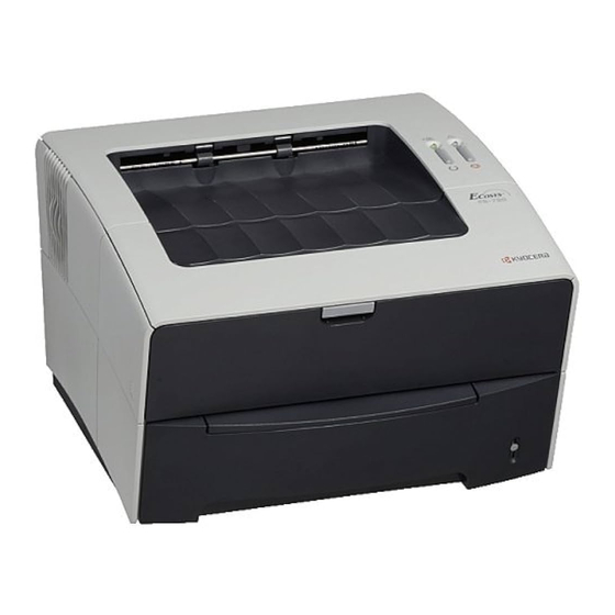
2GL/2FV/2FW 1-1-2 Parts names (1) Printer 16 ppm GDI printer 16/18 ppm printer Figure 1-1-1 Top cover Right side cover Operation panel Rear cover Output tray 10. AC inlet Paper cassette 11. Power switch Manual feed tray 12. Toner container Paper gauge 13. - Page 18 2GL/2FV/2FW (2) Operation panel READY ATTENTION indicator indicator GO key CANCEL key Figure 1-1-2 1-1-8...
-
Page 19: Cross Section View
2GL/2FV/2FW 1-1-3 Cross section view Paper path Figure 1-1-3 Paper cassette Drum unit Manual feed tray Laser scanner unit Paper feeding/conveying section Transfer section Toner container 10. Fuser unit Developer unit 11. Paper exit section Main charger unit 12. Output tray 1-1-9... - Page 20 2GL/2FV/2FW This page is intentionally left blank. 1-1-10...
-
Page 21: Drum Unit And Developer Unit
2GL/2FV/2FW 1-2 Handling Precautions 1-2-1 Drum unit and developer unit Note the following when handling or storing the drum (drum unit). • When removing the drum (drum unit), never expose the drum surface to strong direct light. • Avoid abrupt changes in temperature and humidity. •... - Page 22 2GL/2FV/2FW This page is intentionally left blank. 1-2-2...
-
Page 23: Unpacking And Installation
2GL/2FV/2FW 1-3 Installation 1-3-1 Unpacking and installation (1) Installation procedure Start Unpacking. Installing the toner container. Loading paper. Connecting the cable. Printing a status page for test. Completion of the machine installation. Figure 1-3-1 1-3-1... - Page 24 2GL/2FV/2FW Unpacking. Figure 1-3-2 Unpacking Printer Installation guide Toner container Power cord CD-ROM 1-3-2...
- Page 25 2GL/2FV/2FW Installing the toner container. 1. Rotate the toner container 5 to 6 times and then shake the container horizontally to dis- Toner container tribute the toner evenly. 2. Remove the label from the toner container. Label Figure 1-3-3 3. Turn the toner container release lever to the Toner container [UNLOCK] position.
- Page 26 2GL/2FV/2FW Loading paper. 1. Pull the paper cassette completely out of the printer. Paper cassette Figure 1-3-5 2. Push on the base plate until it click into posi- tion (flat). 3. Adjust the paper length guide and paper Paper width guides to the paper size required. 4.
- Page 27 2GL/2FV/2FW Connecting the cable. 1. Connect the printer cable to the USB or par- allel (16/18 ppm printers only) interface con- nector. 2. Connect the other end of the printer cable to the PC’s interface connector. 3. Connect the power cord to the printer AC inlet.
-
Page 28: Installing Expansion Memory (Optional For 16/18 Ppm Printers)
2GL/2FV/2FW 1-3-2 Installing expansion memory (optional for 16/18 ppm printers) <Procedure> 1. Turn off printer power. Memory (DIMM) * Caution: Do not insert or remove expansion memory while printer power is on. Memory socket Doing so may cause damage to the printer and the expansion memory. -
Page 29: Installing A Memory Card (Optional For 16/18 Ppm Printers)
2GL/2FV/2FW 1-3-3 Installing a memory card (optional for 16/18 ppm printers) <Procedure> 1. Turn off printer power. * Caution: Do not insert or remove memory card while printer power is on. Doing so may cause damage to the printer and the mem- ory card. - Page 30 2GL/2FV/2FW This page is intentionally left blank. 1-3-8...
-
Page 31: Service Mode
2GL/2FV/2FW 1-4 Maintenance Mode 1-4-1 Service mode The product incorporates several service modes which are activated by using the keys on the operation panel or by com- manding from a PC. (1) Executing service mode Printing service status page (For 16 ppm GDI printer) ....See page 1-4-2. Printing service status page (For 16/18 ppm printers) .... - Page 32 To obtain printer information. Procedure 1. Load the CD-ROM (Kyocera FS-720 Library) supplied with the printer in the optical drive and proceed with software installation according to the instructions given. 2. Starting with Windows’s Menu, browse to the Configuration Tool window following the steps below.
- Page 33 2GL/2FV/2FW Service items Description Printing service sta- Description tus page (For 16/18 Prints a service status page for service purpose. The service status page includes various ppm printers) printing settings and service cumulative. Purpose To acquire the current printing environmental parameters and cumulative information. Procedure Press the GO key for 10 seconds or more.
- Page 34 1 = 0: Overseas, 1: Domestic (Japan) OEM mode only)] bit 2, 3 (Not used) bit 4 = 0: Kyocera, 1: OEM bit 5 = 0: For EU, 1: For US bit 6 = 0: Non MICR mode, 1: MICR mode...
- Page 35 2GL/2FV/2FW Service items Description Items Description Operation panel lock status (displayed 01: Partial lock only when locked) 02: Full lock NVRAM error (displayed only when 01: ID error any error has occurred) 02: Version error 03: Checksum error 04: NVRAM crash error Printable area setting /Top offset/Left offset/Page length/Page width Left offset for each paper source...
- Page 36 2GL/2FV/2FW Service items Description Printing event log Description (For 16/18 ppm print- Prints a history list of occurences of paper jam, self-diagnostics, toner replacements, etc. ers) Purpose Analyze the failure by determining the cause depending on the history of occurrence. Procedure 1.
- Page 37 2GL/2FV/2FW Service items Description [EB20MA001/2FV_1000.001.019][C2][40.00SFLB][01] Firmware version: 2FV_30000.001.024 Released: 15/Jul/2004 Total page 12345 DN:SPL0000000 SN:SPL0000000 Count. Event Count. Service Code 9993 10.48.01.88.01.01 11234 01.6000 10000 01.6000 9992 10.48.01.88.01.01 9999 01.6000 9991 10.48.01.88.01.01 9998 01.6000 9990 10.48.01.88.01.01 9997 01.6000 9989 10.48.01.88.01.01 9996 01.6000 9995...
- Page 38 [First byte/second byte (dis- bit 2, 3 (Not used) played in OEM mode only)] bit 4 = 0: Kyocera, 1: OEM bit 5 = 0: For Europe, 1: For US bit 6 = 0: Non MICR mode, 1: MICR mode...
- Page 39 2GL/2FV/2FW Service items Description Items Description (a) Cause of paper jam cont. 10: Paper does not arrive at the registration sensor. [42] 10: Paper does not arrive at the registration sensor. [43] 11: Paper does not pass the registration sensor. [48] 12: Paper remains at the registration sensor when power is turned on.
- Page 40 2GL/2FV/2FW Service items Description Items Description (e) Detail of paper type (Hexadecimal) cont. 01: Plain 0A: Color 15: Custom 1 02: Transparency 0B: Prepunched 16: Custom 2 03: Preprint 0C: Envelope 17: Custom 3 04: Labels 0D: Cardstock 18: Custom 4 05: Bond 0E: Coated 19: Custom 5...
- Page 41 2GL/2FV/2FW Service items Description Printing test page Description (For 16 ppm GDI Prints a test page for service purpose. A page showing a grid image is printed. printer) Purpose Performs check on operation and printing image. Procedure Press the GO key for 10 seconds or more. Test page will be printed. Figure 1-4-6 Test page (For 16 ppm GDI printer) Toner install mode Description...
- Page 42 2GL/2FV/2FW This page is intentionally left blank. 1-4-12...
-
Page 43: Paper Misfeed Detection
2GL/2FV/2FW 1-5 Troubleshooting 1-5-1 Paper misfeed detection (1) Paper misfeed indication When a paper misfeed occurs, the printer immediately stops printing and flash the ATTENTION indicator. To remove paper misfeed in the printer, pull out the paper cassette or open the rear cover. ATTENTION indicator Figure 1-5-1 Paper misfeed indication... - Page 44 2GL/2FV/2FW (2) Paper misfeed detection Registration Exit sensor sensor Figure 1-5-2 Paper misfeed detection 1-5-2...
-
Page 45: Self-Diagnosis
2GL/2FV/2FW 1-5-2 Self-diagnosis (1) Self-diagnostic function When a self diagnostics error occurs, the printer halts and displays the appropriate error code using a combination of the READY and ATTENTION indicators. LED indicator ATTENTION indicator (Amber) Indication example READY indicator (Green) Example: self-diagnostic code: E6 (F050) The ATTENTION indicator means 1 when it flashes in synchronization with the READY indicator which flashes at the interval of 1.2 second;... - Page 46 2GL/2FV/2FW (2) Self diagnostic codes Remarks Code Contents Causes Check procedures/corrective measures 2000 Main motor error Defective harness Follow the flow chart. (E1) • The main motor ready input is not between engine/ given for two seconds during the main high voltage PWB motor is driven.
- Page 47 2GL/2FV/2FW Remarks Code Contents Causes Check procedures/corrective measures 4000 Polygon motor (laser scanner unit) Defective harness Follow the flow chart. (E2) error between engine/ • The polygon motor ready input is not high voltage PWB given for eight seconds during the and laser scanner polygon motor is driven.
- Page 48 2GL/2FV/2FW Remarks Code Contents Causes Check procedures/corrective measures 4200 PD (Pin photo diode) sensor (laser Defective main Follow the flow chart. (E3) scanner unit) error PWB. • The first BD input is not given for 10 Defective harness seconds after power is turned on and between main the laser begins emitting.
- Page 49 2GL/2FV/2FW Remarks Code Contents Causes Check procedures/corrective measures 4200 (E3) Continued from Continued from previous page. previous page. cont. Replace laser scanner unit. See page 1-6-21. Replace main PWB. See page 1-6-15 or 16. Replace main PWB. See page 1-6-15 or 16. Replace harness Turn power switch on.
- Page 50 2GL/2FV/2FW Remarks Code Contents Causes Check procedures/corrective measures 6000 Broken heater lamp error Defective fuser Follow the flow chart. (E4) • The temperature won’t rise by 1 thermistor. degree Celsius during warming up and Broken thermal the heater is turned on for 5 seconds. cutout or heater •...
- Page 51 2GL/2FV/2FW Remarks Code Contents Causes Check procedures/corrective measures 6010 Fuser low temperature Defective the fuser Follow the flow chart. (E4) • After the fuser heater lamp is turned thermistor. on, the temperature at the upper fuser Defective the ° ° roller lower than 100 C/212 F contin-...
- Page 52 2GL/2FV/2FW Remarks Code Contents Causes Check procedures/corrective measures 6050 Broken fuser thermistor Defective the fuser Follow the flow chart. (E4) • The thermistor AD value is less than 1 thermistor. for 3 s. Defective the engine/high volt- age PWB. Start Turn power switch off, and remove power cord.
- Page 53 2GL/2FV/2FW Remarks Code Contents Causes Check procedures/corrective measures 7980 Waste toner full (Total page count less Defective drum Follow the flow chart. (D9) than 100,000 pages of printing) unit. • The toner-full sensor has detected that Defective waste the waste toner is full before the total toner full sensor.
- Page 54 2GL/2FV/2FW Remarks Code Contents Causes Check procedures/corrective measures 7990 Waste toner full (Total page count Defective drum Follow the flow chart. (DA) more than 100,000 pages of printing) unit. • The toner-full sensor has detected that Defective waste the waste toner is full before the total toner full sensor.
- Page 55 2GL/2FV/2FW Remarks Code Contents Causes Check procedures/corrective measures F010 Code ROM checksum error (16/18 Defective code Replace the main PWB. See page 1-6-16. (F1) ppm printers only) ROM (on-board). • Checksum for the code ROM that Defective PWB. Replace the main PWB. See page 1-6-16. holds the system program is wrong.
-
Page 56: Electric Problems
2GL/2FV/2FW 1-5-3 Electric problems Problem Causes Check procedures/corrective measures No electricity at the power Measure the input voltage. The machine does outlet. not operate when the The power cord is not Check the contact between the power plug and the outlet. power switch is plugged in properly. - Page 57 2GL/2FV/2FW Problem Causes Check procedures/corrective measures Broken feed clutch coil. Check for continuity across the coil. If none, replace the feed The feed clutch does clutch. not operate. Poor contact in the feed Reinsert the connector. clutch connector terminals. Defective harness between Check for continuity across the harness.
- Page 58 2GL/2FV/2FW Problem Causes Check procedures/corrective measures (10) Poor contact of transfer See page 1-5-18, 1-6-17. No transfer bias is bias terminal and transfer output. bias terminal (J1, J2, J3) on the engine/high voltage PWB. Defective engine/high volt- age PWB. (11) Defective paper sensor on Replace the engine/high voltage PWB.
-
Page 59: Image Formation Problems
2GL/2FV/2FW 1-5-4 Image formation problems (1) Completely (2) All-black print- (3) Dropouts. (4) Black dots. (5) Black horizon- blank printout. out. tal streaks. See page 1-5-18. See page 1-5-18. See page 1-5-19. See page 1-5-19. See page 1-5-20. (6) Black vertical (7) Unsharpness. - Page 60 2GL/2FV/2FW (1) Completely blank printout. Causes 1. Defective drum unit or developer unit. 2. Defective transfer bias potential. 3. Defective laser scanner unit. 4. Defective main PWB. Causes Check procedures/corrective measures 1. Defective drum unit or developer unit. Open the printer top cover and check that the drum unit and developer unit is correctly seated.
- Page 61 2GL/2FV/2FW (3) Dropouts. Causes 1. Defective developing roller (in the developer unit). 2. Defective drum unit. 3. Defective fuser unit. 4. Defective paper specifications. 5. Defective transfer roller installation. 6. Defective engine/high voltage PWB (transfer bias potential). Causes Check procedures/corrective measures 1.
- Page 62 2GL/2FV/2FW (5) Black horizontal streaks. Causes 1. Defective drum unit’s ground. 2. Defective drum unit Causes Check procedures/corrective measures 1. Defective drum unit’s ground. The drum axle in the drum unit and its counter part, the grounding tab in the printer, must be in a good contact. If necessary, apply a small amount of electro-conductive grease onto the tab.
- Page 63 2GL/2FV/2FW (7) Unsharpness. Causes 1. Defective paper specifications. 2. Defective transfer roller installation. 3. Defective transfer bias potential. 4. EcoPrint setting. Causes Check procedures/corrective measures 1. Defective paper specifications. Paper with rugged surface or dump tends to cause unsharp printing. Replace paper with the one that satisfies the paper specifications.
- Page 64 2GL/2FV/2FW (9) Dirt on the top edge or back of Causes the paper. 1. Toner contamination in various parts. 2. Defective transfer roller. Causes Check procedures/corrective measures 1. Toner contamination in various parts. Dirty edges and back of the paper can be caused by toner accumulated on such parts as the paper chute, paper transportation paths, the bottom of the drum and developer, and the fuser unit inlet.
-
Page 65: Mechanical Problems
2GL/2FV/2FW 1-5-5 Mechanical problems Problem Causes/check procedures Corrective measures Check if the surfaces of the feed roller is dirty Clean with isopropyl alcohol. No primary paper feed. with paper powder. Check if the paper feed roller is deformed. Check visually and replace any deformed paper feed roller. - Page 66 2GL/2FV/2FW This page is intentionally left blank. 1-5-24...
-
Page 67: Precautions For Assembly And Disassembly
2GL/2FV/2FW 1-6 Assembly and Disassembly 1-6-1 Precautions for assembly and disassembly (1) Precautions Be sure to turn the power switch off and disconnect the power plug before starting disassembly. When handling PWBs (printed wiring boards), do not touch parts with bare hands. The PWBs are susceptible to static charge. -
Page 68: Outer Covers
2GL/2FV/2FW 1-6-2 Outer covers (1) Detaching and refitting the top cover <Procedure> 1. Open the top cover. 2. Remove the right side cover. Top cover Right side cover Figure 1-6-1 Removing the right side cover 3. Remove the paper cassette. 4. - Page 69 2GL/2FV/2FW 5. Remove the left cover by removing three hooks and three latches. Hooks Hook : Three latches Left cover (cover inside) Figure 1-6-3 Removing the left cover 6. Remove the one connector. Hook 7. While opening the rear cover and then Hook remove the two screws.
-
Page 70: Paper Feeding/Conveying Section
2GL/2FV/2FW 1-6-3 Paper feeding/conveying section (1) Detaching and refitting the paper feed roller <Procedure> 1. Remove the paper cassette. 2. Remove the paper feed roller. Paper feed roller Figure 1-6-5 Removing the paper feed roller 1-6-4... - Page 71 2GL/2FV/2FW (2) Detaching and refitting the transfer roller <Procedure> 1. Remove the developer unit and drum unit. See page 1-6-6. Paper passing direction 2. Remove the transfer roller from bushes. Short Long Transfer roller Bush Paper passing Transfer roller gear direction Bush (black) Spring...
-
Page 72: Process Section
2GL/2FV/2FW 1-6-4 Process section (1) Detaching and refitting the developer unit and drum unit When replacing the drum unit which was, for example, damaged due to scratches, perform the drum unit optimization pro- cedure. See page 1-6-7. <Procedure> 1. Open the top cover. Top cover 2. - Page 73 2GL/2FV/2FW (2) Drum unit optimization When replacing the drum unit which was, for example, damaged due to scratches, perform the drum unit optimization pro- cedure (drum unit optimization sets the proper main charger current control according to the surface sensitivity of the drum).
- Page 74 2GL/2FV/2FW (3) Detaching and refitting the main charger unit <Procedure> 1. Remove the drum unit. See page 1-6-6. 2 While pushing on the main charger terminal ( ), slide the main charger unit ( ). 3. Remove the main charger unit ( ) by lifting Drum unit Main charger unit Main charger unit...
-
Page 75: Fuser Unit
2GL/2FV/2FW 1-6-5 Fuser unit (1) Detaching and refitting the fuser unit <Procedure> 1. Remove the outer covers. See page 1-6-2. 2. Remove the two connectors. 3. Remove the wire from two clamps. Clamp Connector Wire Clamp Connector Figure 1-6-12 4. Pull out the rear cover axis (with spring) from the axis hole ( ) on side. - Page 76 2GL/2FV/2FW 6. Remove the two screws and then remove the fuser unit. Screw Fuser unit Screw Figure 1-6-14 7. Remove the two screws and then separate the upper fuser frame and lower fuser frame. Lower fuser frame Screw Upper fuser frame Screw Figure 1-6-15 1-6-10...
- Page 77 2GL/2FV/2FW (2) Detaching and refitting the heater lamp, heat roller, fuser thermistor, thermal cutout, and press roller <Procedure> 1. Remove the fuser unit. See page 1-6-9. 2. Remove the two screws and terminal. Screw 3. Remove the heater lamp. Heat gear * Seat the heater lamp aligning its wattage mark and welding mark faced with the cor- rect direction and side.
- Page 78 2GL/2FV/2FW 4. Pull the heat R bush and heat L bush (with Heat gear heat roller) from the upper fuser guide. 5. Remove the heat R bush, heat L bush and Heat R bush heat gear from the heat roller. Heat roller Heat roller Heat L bush...
- Page 79 2GL/2FV/2FW 7. Remove the two screws (nuts), plate cord, and terminal. 8. Remove the thermal cutout. Plate cord Screw Thermal cutout Screw Terminal Figure 1-6-19 1-6-13...
- Page 80 2GL/2FV/2FW 9. Remove the press roller from the bushes. Press roller Bush Bush Lower fuser frame Figure 1-6-20 Removing the press roller 1-6-14...
- Page 81 2GL/2FV/2FW 1-6-6 PWBs (1) Detaching and refitting the main PWB (16 ppm GDI printer) <Procedure> 1. Remove the right cover. See page 1-6-2. 2. Remove the two connectors from main Screw PWB. 3. Remove one screw from the USB interface Main PWB Screw connector.
- Page 82 2GL/2FV/2FW (2) Detaching and refitting the main PWB (16/18 ppm printers) <Procedure> 1. Remove the right cover. See page 1-6-2. 2. Remove the one screw and then remove the Screws CF guide. 3. Remove the two connectors from main PWB. 4.
- Page 83 2GL/2FV/2FW (3) Detaching and refitting the engine/high voltage PWB and power source PWB <Procedure> 1. Remove the developer unit and drum unit. See page 1-6-6. 2. Remove the paper cassette. 3. Remove the outer covers. See page 1-6-2. 4. Remove the six connectors. * When seating the engine/high voltage PWB, ensure that the developer bias terminal spring is correctly in contact with the devel-...
- Page 84 2GL/2FV/2FW 5. Remove the two connectors from main Connectors PWB. 6. Remove the drive unit. See page 1-6-23. Main PWB (16 ppm GDI printer) Connectors Main PWB (16/18 ppm printers) Drive unit Figure 1-6-24 7. Turn the printer bottom side up. Screws 8.
- Page 85 2GL/2FV/2FW 9. Remove the one screw and terminal from the bottom frame plate. * When securing the grounding terminal, hook EEPROM the grounding wire to the projection. Screw 10. Remove the three screws from power Socket source PWB. Screws 11. Remove four screws from the engine/high voltage PWB.
- Page 86 2GL/2FV/2FW 1-6-7 Others (1) Detaching and refitting the laser scanner unit <Procedure> 1. Remove the outer covers. See page 1-6-2. 2. Remove the two screws and then remove Screw the LSU lid. LSU lid Screw Figure 1-6-27 1-6-20...
- Page 87 2GL/2FV/2FW 3. Remove the three screws. Connectors 4. Remove the two connectors and then Screw remove the laser scanner unit. Laser scanner unit Screw Screw Figure 1-6-28 1-6-21...
- Page 88 2GL/2FV/2FW (2) Detaching and refitting the eraser lamp (PWB) <Procedure> 1. Remove the laser scanner unit. See page 1- 6-20. 2. Remove the one connector. 3. Remove the wire from two clamps. Clamps Wire Connector Figure 1-6-29 4. Remove the wire form clamp. Wire 5.
- Page 89 2GL/2FV/2FW (3) Detaching and refitting the drive unit <Procedure> Connectors 1. Remove the right cover. See page 1-6-2. 2. Remove the three connectors. 3. Remove the two screws and then remove the two grounding plates. 4. Remove the two stoppers and then remove the two clutches.
- Page 90 2GL/2FV/2FW (4) Detaching and refitting the main motor <Procedure> 1. Remove the right cover. See page 1-6-2. 2. Remove the one connector from main motor. 3. Remove the four screws and then remove the main motor. Screws Connector Main motor Screws Figure 1-6-33 1-6-24...
- Page 91 2GL/2FV/2FW 1-7 Firmware 1-7-1 Downloading (1) Firmware program data format The data to be downloaded are supplied in the following format: Firmware file name example (For 16/18 ppm printers) S 2 F V _ 1 0 0 0 0 0 1 0 2 1 . c m p Software ID Compression Product code 2FV= 16 ppm printer...
- Page 92 2GL/2FV/2FW (2) Downloading the firmware from the parallel interface (For 16/18 ppm printers) This section explains how to download firmware data from the parallel interface. The printer system can automatically rec- ognize whether the data to be overwritten is for controller firmware. CAUTION Downloading the firmware takes several minutes.
- Page 93 2GL/2FV/2FW 3. Turn printer power on. 4. Confirm that LED indication status ( ) is displayed. 5. At the DOS prompt, enter command. c:\echo!R!UPGR”SYS”;EXIT;>prn 6. Confirm that LED indication status ( ) is displayed. 7. Confirm that LED indication status ( ) is displayed.
- Page 94 2GL/2FV/2FW (3) Downloading the firmware from the memory card (For 16/18 ppm printers) To download data written in a memory card (CompactFlash) to the printer, proceed as explained in this section. CAUTION Downloading firmware takes several minutes. Do not turn power off during downloading. If downloading is interrupted by an accidental power failure, etc., the main PWB may have to be replaced.
- Page 95 2GL/2FV/2FW 4. Turn power switch on. 5. The printers starts and finishes downloading automatically. LED indication status ( )( ) are displayed during downloading. When LED indication status ( ) is displayed to indicate downloading is finished. * If downloading fails, the printer indicates an error display using the LED indicators.
- Page 96 2GL/2FV/2FW This page is intentionally left blank. 1-7-6...
- Page 97 2GL/2FV/2FW 2-1 Mechanical Construction 2-1-1 Paper feeding/conveying section The paper feeding/conveying system picks up paper from the paper cassette, manual feed tray, feeds it in the printer and delivers in the output tray. Paper is feed at the precise timing in synchronization with data processing. (1) Paper feed section The figure below shows the components in the paper feeding/conveying section and the paths through which the paper travels.
- Page 98 2GL/2FV/2FW Engine/high voltage PWB Connect PWB +24V3 YC403-1 YC401-8 Feed clutch YC3-13 FEDSOLON FEDDOLON YC403-2 YC401-3 YC3-8 REGSOLON YC401-2 YC3-7 +24V3 YC402-1 Registration +24V3 YC401-1 YC3-6 REGDR YC402-2 clutch Registration sensor +24V3 CN1-1 YC5-1 Paper sensor YC5-2 CN1-2 MMOTRDY YC5-3 CN1-3 MOTCLK YC5-4...
-
Page 99: Drum Section
2GL/2FV/2FW 2-1-2 Drum section (1) Drum unit The durable layer of organic photoconductor (OPC) is coated over the aluminum cylinder base. The OPC tend to reduce its own electrical conductance when exposed to light. After a cyclic process of charging, exposure, and development, the electrostatic image is constituted over the OPC layer. - Page 100 2GL/2FV/2FW (2) Main charger unit As the drum rotates in a “clean (neutral)” state, its photoconductive layer is given a uniform, positive (+) corona charge dis- persed by the main charger wire. Due to high-voltage scorotron charging, the charging wire can get contaminated by oxi- dization after a long run.
-
Page 101: Expose Section
2GL/2FV/2FW 2-1-3 Expose section (1) Laser scanner unit The charged surface of the drum is then scanned by the laser beam from the laser scanner unit. The laser beam (780 nm wavelength) beam is dispersed as the polygon motor revolves (27959 rpm) to reflect the laser beam over the drum. - Page 102 2GL/2FV/2FW Figure 2-1-7 Laser scanner unit Laser diode ..........Emits diffused, visible laser. Cylindrical lens..........Compensates the vertical angle at which the laser beam hits a polygon mirror segment. Polygon mirror (motor) ......... Has six mirror segments around its hexagonal circumference; each mir- ror corresponding to one scanned line width on the drum when laser beam scans on it.
-
Page 103: Developing Section
2GL/2FV/2FW 2-1-4 Developing section (1) Developer unit The latent image constituted on the drum is developed into a visible image. The developing roller contains a 3-pole (S-N- S) magnet core and an aluminum cylinder rotating around the magnet core. Toner attracts to the developing roller since it is powdery ink made of black resin bound to iron particles. - Page 104 2GL/2FV/2FW Engine/high voltage PWB Developing bias output 350 5 V DC + AC Developing roller Figure 2-1-9 Developing section block diagram 2-1-8...
-
Page 105: Transfer Section
2GL/2FV/2FW 2-1-5 Transfer section The image developed by toner on the drum is transferred onto the paper because of the electrical attraction between the toner itself and the transfer roller. The transfer roller is negatively biased so that the positively charged toner is attracted onto the paper while it is pinched by the drum and the transfer roller. -
Page 106: Cleaning Section
2GL/2FV/2FW 2-1-6 Cleaning section After the transferring process, the drum needs to be physically cleaned of toner which is residual after the development process. The cleaning blade is constantly pressed against the drum and scrapes the residual toner off to the sweep roller. The waste toner is collected at the output end of the sweep roller and sent back to the toner container, into the waste toner reservoir. -
Page 107: Fuser Section
2GL/2FV/2FW 2-1-7 Fuser section (1) Fuser unit The toner on the paper is molten and pressed into the paper as it passes between the heat roller and the press roller in the fuser unit. The heat roller has a heater lamp (750 W) inside which continuously turns on and off by the fuser thermistor to maintain the constant temperature onto the heat roller surface. - Page 108 2GL/2FV/2FW Fuser unit Power source PWB Engine/high voltage PWB Thermal cutout HEATN YC2-6 YC1-6 CN1-1 SLEEP YC2-7 YC1-7 ZCROSS CN1-3 YC2-9 YC1-9 Heater lamp Fuser thermistor YC7-2 THERM YC7-1 Figure 2-1-15 Fuser section block diagram 2-1-12...
-
Page 109: Paper Exit Section
2GL/2FV/2FW 2-1-8 Paper exit section (1) Paper exit section The paper exit section transports the paper which passed the fuser unit towards the output tray. The paper which passed through the fuser unit turns on the exit sensor which is driven by the fuser actuator in the fuser unit, and is led by the guide comprised of the rear cover and the frame, finally reaching the FD roller. - Page 110 2GL/2FV/2FW Fuser unit Engine/high voltage PWB YC2-8 EXITN YC1-8 Exit sensor Power source PWB Figure 2-1-17 Paper exit section block diagram 2-1-14...
- Page 111 2GL/2FV/2FW 2-2 Electrical Parts Layout 2-2-1 Electrical parts layout (1) Electrical parts layout Drum unit Fuser unit Developer unit Laser scanner unit Figure 2-2-1 Electrical parts layout Main PWB (For 16 ppm GDI printer).... Controls the software such as the print data processing and provides the interface with computer.
- Page 112 2GL/2FV/2FW 20. Feed clutch ..........Controls the paper cassette paper feed. 21. Registration clutch ........Controls the primary paper feed. 22. AC inlet ............Connects the AC power source. 23. Thermal cutout ..........Shuts off the power source to the heater lamp when the heat roller reaches extremely high temperature.
- Page 113 2GL/2FV/2FW 2-3 Operation of the PWBs 2-3-1 Power source PWB Power source PWB Power Rectification switch smoothing circuit input Noise D10 to 13 NTC1 24V1 filter circuit 24 V DC (L1) rectification/ smoothing output circuit 5 V DC Switching Overvoltage rectification/ control detection...
- Page 114 2GL/2FV/2FW Connector Pin No. Signal Voltage Description 220 - 240 V AC AC power input 120 V AC Connected to the AC 220 - 240 V AC AC power input inlet 120 V AC 220 - 240 V AC Power supply for heater lamp (On/Off) 120 V AC Connected to the heater...
- Page 115 2GL/2FV/2FW 2-3-2 Engine/high voltage PWB Engine/high voltage PWB Connect EECLK EEPROM EEDIO (U2) FPSW Operation FPLED1, FPLED2 panel PWB BUZZ RESETN Reset IC (U3) Buzzer REGSOLON Registration clutch FANH Cooling fan FEDSOLON Feed clutch motor FANL MMOTON TONER Toner empty MOTCLK sensor Main motor...
- Page 116 2GL/2FV/2FW Connector Pin No. Signal Voltage Description 5 V DC 5 V DC power input Connected 5 V DC 5 V DC power input to the power Ground source PWB Ground +24V2 24 V DC 24 V DC power output (via interlock switch) HEATN 0 /24 V DC Heater lamp: On/Off...
- Page 117 2GL/2FV/2FW Connector Pin No. Signal Voltage Description ERASPW 24 V DC 24 V DC power output Connected ERASER 0/24 V DC Eraser lamp (PWB): On/Off to the eraser lamp (PWB) +24V1 24 V DC 24 V DC power output Connected 0 /12/24 V DC Cooling fan motor: Full speed/Half speed/Off to the cool-...
- Page 118 2GL/2FV/2FW 2-3-3 Main PWB For 16 ppm GDI printer SDRAM address bus SDA11-0 OSC (USB) (System) SYSCK RASN, CASN, WEN, BA1, BA0 DQML, D1QMU SDRAM 48.000 MHz SDCSN0 SDCLK SDD15-0 SDRAM data bus USBDP RISC CPU USBDN (Core+ASIC) FSSO FSSI FSCK RESIN, ESTSN Flash...
- Page 119 2GL/2FV/2FW For 16 ppm printer EBA22-1 EBIU address bus Xtal (video) VXIN EBA21-1 37.6687 MHz VXOUT EBCSN0-1, Code EBOEN0, EBWEN0 (Flash EBD31-16 memory) CXIN OSC (USB) (System) UXIN YC01 48.000 MHz EBCSN2, EBA22, EBA10-1 EBOEN1, EBWEN1 Memory CDWAITN, CDET YC02 card CDRST USBDP...
- Page 120 2GL/2FV/2FW For 18 ppm printer Xtal (System) EBA22-1 EBIU address bus CXIN 33.3333 MHz CXOUT EBA21-1 Xtal (video) Code EBCSN0-1, EBOEN0, EBWEN0 VXIN 37.6687 MHz VXOUT (Flash EBD31-16 memory) OSC (USB) (System) UXIN YC01 48.000 MHz EBCSN2, EBA22, EBA10-1 EBOEN1, EBWEN1 Memory CDWAITN, CDET YC02...
- Page 121 2GL/2FV/2FW 2-4 Appendixes 2-4-1 Appendixes (1) Timing chart No.1 Cassette paper feeding, Paper size A4 (For 16/16 ppm GDI printers) 2-4-1...
- Page 122 2GL/2FV/2FW (2) Timing chart No.2 Cassette paper feeding, Paper size A4 (For 18 ppm printer) 2-4-2...
- Page 123 2GL/2FV/2FW (3) Timing chart No.3 Manual feed tray paper feeding, Paper size A4 2-4-3...
- Page 124 2GL/2FV/2FW (4) Wiring diagram 2-4-4...
- Page 125 2GL/2FV/2FW (5) Repetitive defects gauge First occurrence of defect [24 mm] Upper registration roller [38 mm] Lower registration roller [47.2 mm] Developing roller (Developer unit) [48 mm] Transfer roller [63 mm] Heat roller, Press roller (Fuser unit) [94 mm] Drum (Drum unit) 2-4-5...
- Page 126 2GL/2FV/2FW This page is intentionally left blank. 2-4-6...