Motorola APX 6000 User Manual
Hide thumbs
Also See for APX 6000:
- User manual (146 pages) ,
- Manual (105 pages) ,
- Service manual (438 pages)
Table of Contents
Advertisement
Advertisement
Table of Contents

Related Manuals for Motorola APX 6000


Summary of Contents for Motorola APX 6000
- Page 1 APX™ TWO-WAY RADIOS APX 6000 / APX 6000Li MODEL 3 USER GUIDE...
- Page 3 PMLN5717E MOTOROLA, MOTO, MOTOROLA SOLUTIONS and the Stylized M logo are trademarks or registered trademarks of Motorola Trademark Holdings, LLC and are used under license. All other trademarks are the property of their respective owners. © 2011–2013 by Motorola Solutions, Inc. All Rights Reserved. 10/13 English 1303 East Algonquin Road, Schaumburg, Illinois 60196, U.S.A.
-
Page 4: Sending A Silent Emergency Call
Sending an Emergency Call On = Secure operation. Blinks when the battery is low. Off = Clear operation. Press the Emergency button. Blinking = Receiving an encrypted The more stripes, the stronger the voice call. signal strength for the current site Press and hold the PTT button. -
Page 5: Table Of Contents
Contents Documentation Copyrights...15 Disclaimer........16 Declaration of Conformity......8 Important Safety Information..10 Getting Started....... 17 How to Use This Guide........17 Notations Used in This Manual......17 Software Version......11 Additional Performance Enhancement..17 Notice to Users (FCC and Industry ASTRO 25 Enhanced Data....17 Canada)............11 Dynamic System Resilience (DSR).. - Page 6 Attaching the Antenna........21 Keypad Characters – Hexadecimal Removing and Attaching the Accessory Mode..........38 Connector Cover........22 Push-To-Talk (PTT) Button......39 Using the Carry Holder........23 Turning On the Radio........25 Identifying Status Indicators..40 Adjusting the Volume........26 Status Icons........... 40 Text Messaging Service (TMS) Indicators..44 Identifying Radio Controls....
- Page 7 Saving a Zone and a Channel to a Selective Call (ASTRO Button..........58 Conventional Only)......66 Receiving and Responding to a Radio Call... 58 Talkgroup Call Feature Receiving and Responding to a (Conventional Operation Only)..67 Talkgroup Call........58 Sending a Status Call......68 Receiving and Responding to a Responding to the Dynamic Private Call (Trunking Only)...59...
- Page 8 Making a Dynamic Priority Change Post-Alert Timer........92 (Conventional Scan Only)....81 Radio Alerts When Man Down Deleting a Nuisance Channel..... 81 Feature is Triggered...... 93 Restoring a Nuisance Channel... 82 Triggering Emergency......93 Call Alert Paging..........82 Radio Alerts When Man Down Receiving a Call Alert Page....
- Page 9 Bluetooth Drop Timer......139 Saving a Waypoint......127 Pairing with Low Frequency- Viewing a Saved Waypoint....127 Motorola Proximity Pairing (LF- Editing the Alias of a Waypoint..128 MPP) Feature......140 Editing the Coordinates of a Radio Indications of Lost Bluetooth Waypoint........
- Page 10 Turning Off the Bluetooth Audio Stopping SSA Notification of a (Routing the Audio from the Single Site Via Manual Entry..157 Headset to the Radio)....148 Stopping SSA Notification of All Adjusting the Volume of the Radio Sites..........158 from Bluetooth Audio Device..148 Stopping SSA Notification of All Viewing and Clearing the Bluetooth Available Sites......
- Page 11 Glossary........184 Helpful Tips........174 Radio Care...........174 Limited Warranty......190 Cleaning Your Radio......175 Proper Ways to Handle the Radio..175 MOTOROLA COMMUNICATION Radio Service and Repair....175 PRODUCTS........... 190 Battery Care..........176 I. WHAT THIS WARRANTY COVERS Battery Charge Status.......176 AND FOR HOW LONG:......190 Battery Recycling and Disposal..
-
Page 12: Declaration Of Conformity
Address: 1303 East Algonquin Road, Schaumburg, IL 60196-1078, U.S.A. Phone Number: 1-800-927-2744 Hereby declares that the product: Model Name: APX 6000/ APX 6000Li conforms to the following regulations: FCC Part 15, subpart B, section 15.107(a), 15.107(d) and section 15.109(a) English... - Page 13 Class B Digital Device As a personal computer peripheral, this device complies with Part 15 of the FCC Rules. Operation is subject to the following two conditions: 1 This device may not cause harmful interference, and 2 This device must accept any interference received, including interference that may cause undesired operation. Note: This equipment has been tested and found to comply with the limits for a Class B digital device, pursuant to part 15 of the FCC Rules.
-
Page 14: Important Safety Information
Radios which contains important operating instructions for safe usage and RF energy awareness and control for Compliance with applicable standards and Regulations. For a list of Motorola-approved antennas, batteries, and other accessories, visit the following website: http://www.motorolasolutions.com/APX Under Industry Canada regulations, this radio... -
Page 15: Software Version
This device may not cause harmful interference. • This device must accept any interference received, including interference that may cause undesired operation. • Changes or modifications made to this device, not expressly approved by Motorola, could void the user's authority to operate this equipment. English... -
Page 16: Consignes De Sécurité Importantes
Cet émetteur radio a été approuvé par Industrie Canada pour utilisation avec une antenne approuvée Cette radio ne doit être utilisée qu'à des fins par Motorola offrant le gain maximal autorisé et professionnelles. Avant d'utiliser la radio, lisez le l'impédance requise pour le type d'antenne indiqué. Il... -
Page 17: Version Logicielle
Motorola, peuvent annuler le droit de l'utilisateur à Version logicielle utiliser cet équipement. Toutes les fonctions décrites dans les sections suivantes sont prises en charge par la version R13.00.00 ou les versions ultérieures du logiciel de la radio. Pour obtenir davantage de renseignements à propos des fonctions prises en charge, adressez-vous à... -
Page 18: Computer Software Copyrights
Motorola. Furthermore, the purchase of Motorola products shall not be deemed to grant either directly or by implication, estoppel, or otherwise, any license under the copyrights, patents or patent... -
Page 19: Documentation Copyrights
No duplication or distribution of this document or any portion thereof shall take place without the express written permission of Motorola. No part of this manual may be reproduced, distributed, or transmitted in any form or by any means, electronic or mechanical, for any purpose without the express written permission of Motorola. -
Page 20: Disclaimer
However, no responsibility is assumed for inaccuracies. Furthermore, Motorola reserves the right to make changes to any products herein to improve readability, function, or design. Motorola does not assume any liability arising out of the applications or use of any product or circuit described herein;... -
Page 21: Getting Started
Note: An operational procedure, practice, or condition Getting Started and so on, which is essential to emphasize. The following special notations identify certain items. How to Use This Guide Example Description This User Guide covers the basic operation of the APX Portables. -
Page 22: Dynamic System Resilience (Dsr)
SecureNet allows user to perform secured Dynamic System Resilience (DSR) communications on an Analog or Motorola Data Communication (MDC) channel. The MDC Over-the- DSR ensures the radio system is seamlessly Air Rekeying (OTAR) feature will allow users to switched to a backup master site dynamically in case perform OTAR activities on an MDC channel. -
Page 23: What Your Dealer/System Administrator Can Tell You
can be supported when Vote Scan channels are Note: Specifications may vary for different radio being used. models. Check with your dealer or system administrator for more information. Smart PTT is supported with this enhancement as Smart PTT prevents users from transmitting while other users are on the channel. -
Page 24: Preparing Your Radio For Use
Note: When charging a battery attached to a radio, turn the radio off to ensure a full charge. To charge the battery, place the battery (with or without the radio) in a Motorola-approved charger. The LED on the charger indicates the charging progress; see the charger user guide. -
Page 25: Attaching The Antenna
2 To remove the battery, squeeze the release Attaching the Antenna latches at the bottom of the battery until the battery releases from the radio and remove the Ensure the radio is turned off before attaching the battery from the radio. antenna. -
Page 26: Removing And Attaching The Accessory Connector Cover
Note: To prevent damage to the connector, shield it with the connector cover when not in use. 1 To remove the accessory connector cover, rotate the thumbscrew counterclockwise until it disengages from the radio. Note: If the thumbscrew is too tight, use an Allen wrench at to loosen it first. -
Page 27: Using The Carry Holder
3 To attach the accessory connector cover, insert the hooked end of the cover into the slot above the connector. 4 Press downward on the cover’s top to seat it in the slot. 5 Once in place, tighten by rotating the thumbscrew clockwise by hand. - Page 28 4 Push at the bottom of the radio until the radio is 3 To remove the radio from the carry holder, place released from it. the tip of your fingers on the ledge of the carry holder. English...
-
Page 29: Turning On The Radio
• If the power-up test is successful, you see Turning On the Radio momentary SELFTEST on the radio display, followed by the Home screen. 1 Rotate the On/Off/Volume Control Knob clockwise until you hear a click. • If the power-up test is unsuccessful, you see Error XX/YY (XX/YY is an alphanumeric code). -
Page 30: Adjusting The Volume
2 To turn off the radio, rotate the On/Off/Volume 1 To increase the volume, rotate the On/Off/Volume Control Knob counterclockwise until you hear a Control Knob clockwise. click. 2 To decrease the volume, rotate this knob counterclockwise. Adjusting the Volume Ensure the radio is power on and the main speaker is pointed towards you for increased loudness and intelligibility, especially in areas with loud background... -
Page 31: Identifying Radio Controls
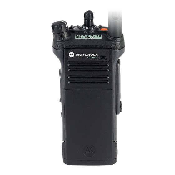
Identifying Radio Controls Radio Parts and Controls Antenna Top (Orange) Button Microphone English... -
Page 32: Programmable Features
Accessory Connector Bluetooth Pairing Location Indicator Home Button Main Speaker 4–Way Navigation Button Microphone Battery Latch Top Display Keypad 16–Position Select Knob Data Feature Button Menu Select Buttons Programmable Features Main Display Any reference in this manual to a control that is 2–Position Concentric Switch preprogrammed means that the control must be 3–Position A/B/C Switch... -
Page 33: Assignable Radio Functions
Long Press Pressing and holding for the Bluetooth Inquiry Enables Bluetooth Search preprogrammed duration (between On/Off feature. 0.25 seconds and 3.75 seconds). Bluetooth Enables Bluetooth visibility. Hold down Keeping the button pressed. Discoverable This is accessed by a long On/Off press of the Bluetooth Inquiry Assignable Radio Functions On/Off Button. - Page 34 Emergency Depending on the Mode Select Long-press programs a button programming, initiates or with the current zone and cancels an emergency alarm or channel of the radio; once call. programmed, the short-press of that button changes the radio Information Displays the information of the zone channel to the radio.
- Page 35 Phone Allows you to make and receive (Conventional calls similar to standard phone Only) calls. Reprogram Notifies the dispatcher you want Private Call Allows a call from an individual Request a new dynamic regrouping (Trunking Only) radio to another individual (Trunking Only) assignment.
-
Page 36: Assignable Settings Or Utility Functions
Site Display/ Displays the current site ID and Zone Select Allows selection from a list of Search (Trunking RSSI value; performs site zones. Only) search for Automatic Multiple Basic Zone Bank Provides access from up to 6 Site Select (AMSS) or zones by toggling between 2 SmartZone operation. -
Page 37: Accessing The Preprogrammed Functions
Voice Audibly indicates the current Announcement feature mode, Zone or Channel the user has just assigned. Voice Mute Toggles voice mute on or off. Volume Set Tone Sets the volume set tone. Accessing the Preprogrammed Functions You can access various radio functions through one Softkeys of the following methods. -
Page 38: Home Button
example, but the steps for selecting a channel may • Press and hold one of the button to have the radio appear as shown below: toggles through the list automatically (release the button to stop). Press the Menu Select button directly below Chan. Data Feature Button Home Button Use Data Feature button to access data-related... -
Page 39: Keypad Characters - Uppercase Mode
Keypad Characters – Uppercase Mode Number of Times Key is Pressed & “ ‘ Toggle between mixed case mode, uppercase mode and lowercase mode. Space Toggle between numeric and letter mode. English... -
Page 40: Keypad Characters - Lowercase Mode
Keypad Characters – Lowercase Mode Number of Times Key is Pressed & “ ‘ Toggle between mixed case mode, uppercase mode and lowercase mode. Space Toggle between numeric and letter mode. English... -
Page 41: Keypad Characters - Numeric Mode
Keypad Characters – Numeric Mode Number of Times Key is Pressed & “ ‘ Space Toggle between numeric and letter mode. English... -
Page 42: Keypad Characters - Hexadecimal Mode
Keypad Characters – Hexadecimal Mode Number of Times Key is Pressed Not applicable Not applicable English... -
Page 43: Push-To-Talk (Ptt) Button
• While a call is not in progress, the PTT button is Push-To-Talk (PTT) Button used to make a new call. See Making a Radio Call on page 60 for more information. The PTT button on the side of the radio serves two basic purposes: •... -
Page 44: Identifying Status Indicators
Identifying Status Indicators Call Received Status Icons Radio has received an Individual Call. The 130 x 130 pixel front liquid crystal display (LCD) of your radio shows radio status, text entries, and Battery menu entries. The top two display rows contain color For IMPRES battery operation only –... - Page 45 Off – The feature is disabled. Voice Display: muting of the affiliated trunking talkgroup or selected conventional channel is deactivated. Power Level Direct L – Radio is set at Low power. On – Radio is currently configured for Display: direct radio-to-radio communication H –...
- Page 46 View/Program Mode Enhanced Zone Bank Display: Display: Radio is in the view or program mode. A – Contains Zone 1, Zone 2 and Zone On steady – View mode B – Contains Zone 4, Zone 5 and Zone Blinking – Program mode C –...
- Page 47 Inverted – User successfully login to the AES Secure Operation secured IP Packet Data. On – AES secure operation. Off – Clear operation. Data Activity Blinking – Receiving an encrypted Data activity is present. voice call. Hexadecimal GPS Signal Indicates that the text entry is currently On –...
-
Page 48: Text Messaging Service (Tms) Indicators
Uppercase Bluetooth On Indicates that the text entry is currently Bluetooth is on and ready for Bluetooth in uppercase mode. connection. Display: Lowercase Indicates that the text entry is currently in lowercase mode. Bluetooth Connected Lowercase Predictive Bluetooth is currently connected to the Indicates that the text entry is currently external Bluetooth device. -
Page 49: Tms Status Icons
TMS Status Icons Normal Message The following icons appear on the radio’s display User is composing a message with normal when you send and receive text messages. priority and without a request for a reply. Inbox Full Message Index The Inbox is full. Indicates the index of the current message the user is viewing. -
Page 50: Tms Menu Options
Menu Description/Function Priority Status and Request Reply Option • User is composing a message with a Sends the message. Send priority status and a request for a reply. • Messages in the Inbox folder are Updates or saves a command. flagged with “Priority”... -
Page 51: Led Indicator
Landline phone number. Landline phone number added to a Call List. Incoming call or data. Outgoing call or data. Incoming emergency call. Solid red Radio is transmitting. Blinking red Radio is transmitting at low battery condition. LED Indicator Double blinking Radio is in Emergency Mode. -
Page 52: Intelligent Lighting Indicators
Solid green Radio is powering up, or is on the Scan List Programming a non-priority channel while in mode. the Scan List Programming Rapidly blinking Radio is on a Priority-One mode. green channel while in the Scan List Blinking green Radio is receiving an individual Programming mode. -
Page 53: Alert Tones
Backlight and Bar Notification When Color The radio initiates Fireground Evacuation alarm. Critical Alerts The radio battery is low. The radio is out of range. The radio enters Failsoft mode. The radio is unable to establish a full connection with the system. The radio is unable to authenticate or register with the system. - Page 54 You Hear Tone Name Heard Short, Low- Radio Self Test Fail When radio fails its power-up self test. Pitched Tone Reject When an unauthorized request is made. Time-Out Timer Warning Four seconds before time out. No ACK Received When radio fails to receive an acknowledgment. Individual Call Warning When radio is in an individual call for greater than 6 seconds Tone...
- Page 55 You Hear Tone Name Heard A Group of Busy When system is busy. Low-Pitched Tones Short, Medium- Valid Key-Press When a correct key is pressed. Pitched Tone Radio Self Test Pass When radio passes its power-up self test. Clear Voice At beginning of a non-coded communication.
- Page 56 You Hear Tone Name Heard Received Individual Call When Call Alert or Private Call is received. Call Alert Sent When Call Alert is received by the target radio. Site Trunking When a SmartZone trunking system fails. Short, High- Low-Battery Chirp When battery is below preset threshold value.
-
Page 57: Phone Call Displays And Alerts
You Hear Tone Name Heard Incremental- Bluetooth Paired When Bluetooth accessory is paired with the radio. Pitched Tone Bluetooth Connected When Bluetooth accessory is connected to the radio. Decremental- Bluetooth Unpaired When Bluetooth accessory is unpaired from the radio. Pitched Tone Bluetooth Disconnected When Bluetooth accessory is disconnected from the radio. - Page 58 You Hear You See When Notes A Long Tone No phone You press the PTT button Press to hang up. The radio returns to the and the phone system is Home screen. not available. Phone busy The phone system is busy. Press to exit the phone mode and try your call later.
-
Page 59: General Radio Operation
• Select a zone via the radio menu Zone: General Radio Operation or to Zone and press the Menu Select button directly below Zone. Selecting a Zone to the required zone, or use the Your radio must be preprogrammed to allow you to keypad to enter the zone number. -
Page 60: Selecting A Radio Channel
d) Press the Menu Select button directly below Selecting a Radio Channel Sel to confirm the selected channel. e) Press the PTT button to transmit on the A channel is a group of radio characteristics, such as displayed zone channel. transmit/ receive frequency pairs. -
Page 61: Mode Select Feature
• Press the preprogrammed Channel Search again; or press or the Menu Select button directly button. below Exit to exit. • or to CSrh and press the Menu Select Mode Select Feature button directly below CSrh. A blinking cursor appears on the Channel Search Mode Select allows a long press to save the current screen. -
Page 62: Saving A Zone And A Channel To A Button
Note: Repeat this procedure to change the zone and or to MS1, MS2 ... or MS5. channel of the programmed button. Short press of the programmed button 3 Press and hold the Menu Select button directly below one of the softkey (MS1 – MS5). Short press of the programmed button changes your current transmission to the zone and channel You hear a short, medium-pitched tone when the... -
Page 63: Receiving And Responding To A Private Call (Trunking Only)
one of the following scenarios depending on the receiving radio is active on the system and can system your radio is configured: display the caller ID. • For ASTRO Conventional system, the LED lights Note: With the inactivity timer enabled (optional), up solid yellow. -
Page 64: Receiving And Responding To A Telephone Call (Trunking Only)
3 Press 3 Press or the Call Response button to hang up or the Call Response button to hang up and return to the Home screen. and return to the Home screen. See also Making a Private Call (Trunking Only) See also Making a Telephone Call (Trunking Only) page 61 for details on making a Private Call. -
Page 65: Making A Private Call (Trunking Only)
1 Turn the 16-Position Select Channel Knob to 1 Perform one of the following actions: select the channel with the desired talkgroup. • To access this feature via a preprogrammed button, press the preprogrammed Quick 2 Hold the radio vertically 1 to 2 inches (2.5 to 5.0 Access (One-Touch) Private Call button to cm) from your mouth. -
Page 66: Making An Enhanced Private Call (Trunking Only)
Access (One-Touch) Enhanced Private Call The display shows Calling... <Number>. button to dial the preprogrammed ID (number) 5 Hold the radio vertically 1 to 2 inches (2.5 to 5.0 and initiate the Private Call. Proceed to step 5. cm) from your mouth. •... -
Page 67: Making A Telephone Call (Trunking Only)
When you are connected, the display shows the or to Phon, and press the Menu Select button ID of the target radio. directly below Phon. If no acknowledgment is received, the display The display shows the last transmitted or received shows No acknowledge. -
Page 68: Switching Between Repeater Or Direct Operation Button
The display shows Direct mode and the Talkaround 7 Press to return to the Home screen. icon if the radio is currently in Direct mode (during conventional operation only). Phone Call Displays and Alerts on page 53 for more information if your call is NOT answered. Monitor Feature Switching Between Repeater or Direct Radio users who switch from analog to digital radios... -
Page 69: Monitoring Conventional Mode
c) Adjust the Volume Control Knob if necessary. Monitoring Conventional Mode d) Release the Volume Set button. Your radio may be preprogrammed to receive Private- e) Press and hold the PTT button to transmit. ® Line (PL) calls. The LED lights up solid red. 1 Momentarily press the Monitor button to listen for f) Release the PTT button to receive (listen). -
Page 70: Advanced Features
2 Press and hold the PTT button to talk. Release the Advanced Features PTT button to listen. Advanced Call Features Making a Selective Call Selective Call (ASTRO Conventional Only) 1 Perform one of the following actions: This feature allows you to receive a call from or to call •... -
Page 71: Talkgroup Call Feature (Conventional Operation Only)
• to the required ID. Selecting a Talkgroup • Use the keypad to enter the required ID. or to Tgrp and press the Menu Select button 4 Hold the radio vertically 1 to 2 inches (2.5 to 5.0 directly below Tgrp. cm) from your mouth. -
Page 72: Sending A Status Call
Sending a Status Call When the dispatcher acknowledges, you hear four tones and the display shows Ack received . The This feature allows you to send data calls to the radio returns to normal dispatch operation. dispatcher about a predefined status. If no acknowledgment is received, you hear a low- Each status can have up to a 14-character name. - Page 73 Note: If you try to access a zone or channel that has • or to Rpgm then press the Menu Select been reserved by the dispatcher as a dynamically button directly below Rpgm to send reprogram regrouped mode for other users, you hear an invalid request to the dispatcher.
-
Page 74: Dynamic Zone Programming (Dzp)
Entering the Dynamic Zone to Select a Dynamic Select Select-disabled radios cannot change Channel Disabled channels while dynamically regrouped. The dispatcher has forced the radio to or to Zone then press the Menu Select button remain on the dynamic-regrouping directly below Zone. channel. - Page 75 Saving a Channel in the Dynamic Zone from List 6 Press theMenu Select button directly below Exit Selection to return to Home screen. The radio must be in Dynamic Zone in order to Saving a Channel in the Dynamic Zone from perform this operation.
-
Page 76: Contacts
You can cancel this operation at this step by 3 Press the Menu Select button below Exit to pressing the Menu Select button directly below return to Home screen. Cncl to return to Search Options screen. The Home screen shows <Dynamic Zone The display shows Searching.. -
Page 77: Making A Private Call From Contacts
• Call Type (Icon) 3 Perform one of the following actions: • WACN ID (Astro 25 Trunking IDs only) • Press the Menu Select button directly below • System ID Optn and proceed to the next step. Note: Your radio must be preprogrammed to allow •... -
Page 78: Adding A New Contact Entry
If the call reaches the maximum ring time, the call to Number 1 and press the Menu Select ends. button directly below Edit. The display shows Edit Number 1 and a blinking Adding a New Contact Entry cursor appears. or to Cnts and press the Menu Select button 7 Use the keypad to enter the number and press directly below Cnts. -
Page 79: Deleting A Contact Entry
Adding a Contact to a Call List The display shows <Entry> Stored, confirming that the contact entry has been added. or to Cnts and press the Menu Select button The radio returns to the main Contacts screen. directly below Cnts. The entries are alphabetically sorted. -
Page 80: Removing A Contact From A Call List
Removing a Contact from a Call List Editing an Entry Alias or to Cnts and press the Menu Select button or to Cnts and press the Menu Select button directly below Cnts. directly below Cnts. The entries are alphabetically sorted. The entries are alphabetically sorted. - Page 81 Editing as Entry ID Editing a Call Type or to Cnts and press the Menu Select button or to Cnts and press the Menu Select button directly below Cnts. directly below Cnts. The entries are alphabetically sorted. The entries are alphabetically sorted. to the entry you want to edit and press to the entry you want to edit and press the Menu Select button directly below Optn.
-
Page 82: Viewing Details Of A Contact
Viewing Details of a Contact Please refer to a qualified radio technician for the maximum number of Scan Lists can be programmed in your radio. These lists must be preprogrammed by or to Cnts and press the Menu Select button a qualified radio technician. -
Page 83: Changing The Scan List Status
The display shows the lists that can be changed. • Move the Scan List Programming switch out of programming position. to the entry you want to edit. • Press to exit scan list programming and return to the Home screen. 3 Perform one of the following actions: •... -
Page 84: Viewing And Changing The Priority Status
• Press the Select button one or more times to The radio shows one of following priority status change the scan list status icon of the currently icons and scenarios: displayed channel. • A Scan icon indicates that the current channel is in the scan list as a non-priority channel. -
Page 85: Turning Scan On Or Off
Turning Scan On or Off This change remains in effect until scan is turned off. Scan then reverts to the preprogrammed (original) Perform one of the following actions: setting. • Press the preprogrammed Scan button to Making a Dynamic Priority Change via the toggle Scan On or Scan Off to initiate or stop preprogrammed Dynamic Priority button: scan. -
Page 86: Restoring A Nuisance Channel
• automatically sends a call alert page if there is no or to Nuis and press the Menu Select answer after the maximum ring time, or when you button directly below Nuis. press the PTT button. The radio continues scanning the remaining channels Note: This feature must be preprogrammed by a in the list. - Page 87 is left idle long enough for the time to expire. You c) Press the Menu Select button directly below hear the Menu Inactive Exit Tone upon feature exit. Cnts to view the required ID, to the required ID, or use the keypad to enter the •...
-
Page 88: Emergency Operation
If the target radio does not respond after a If the Top (Orange) button is preprogrammed to send preprogrammed period of time, the display an emergency signal, this signal overrides any other communication over the selected channel. shows Send page?. d) To send the call alert page, press the Menu Your radio supports the following Emergency modes: Select button directly below Yes. -
Page 89: Sending An Emergency Alarm
Tactical/Non- The radio sends emergency Press the preprogrammed Emergency button. Revert alarm and/or make emergency One of the following scenarios occurs: call on the current selected channel. • The display shows Emergency on the current zone and channel. You hear a short medium- Non-Tactical/ The radio reverts to the pitched tone and the LED blinks red... -
Page 90: Sending An Emergency Alarm With Emergency Call
One of the following scenarios will occur: Sending an Emergency Alarm with Emergency Call • The display shows Emergency on the current This feature gives your radio priority access on a zone and channel. You hear a short medium- channel for conventional system, and to a talkgroup for trunking system. -
Page 91: Sending A Silent Emergency Alarm
• You press and hold the preprogrammed 2 Hold the radio vertically 1 to 2 inches (2.5 to 5.0 Emergency button for about a second to exit cm) from your mouth. the Silent Emergency Alarm mode. 3 Press and hold the PTT button. Speak clearly into •... -
Page 92: Fireground (Conventional Only)
Note: The radio only exits the Emergency state using Each Fireground Communication System radio one of the ways mentioned in the previous sections. automatically reports your radio ID on the commander mobile command terminal. Your name, riding position Sending an Emergency Alarm on page 85, and sector are all can be configured to be seen at the Sending an Emergency Call (Trunking Only) -
Page 93: Responding To Evacuation Indicator
• If the Fireground Zone Channel is set as • If your radio is working in Fireground Zone default, you hear gurgle tone and the home Channel, proceed to next step. screen. You are in Fireground zone channel. 4 Press and hold the PTT button to transmit. The •... -
Page 94: Tactical Public Safety(Tps) (Conventional Only)
• If preprogrammed with Manual Emergency During Emergency if the TPS radio Acknowledgement of Evacuation Command, Beacon user pushes the Emergency button, pressing the PTT button shall cancel the the radio sounds a Beacon at the indications and acknowledge the command maximum volume of the radio at terminal. -
Page 95: Man Down
Note: It is recommended that an Emergency button is 4 Long press Emergency button to exit Emergency preprogrammed in order to allow the user to exit the mode and cancel Emergency Beacon. emergency condition. Man Down The Man Down feature provides a Clear function to the user. -
Page 96: Pre-Alert Timer
3 Man Down condition continues for the time When the radio is programmed with Man Down duration defined in the Post-Alert Timer field. Once feature, special care is required when charging the the timer expires, the Emergency alarm is radio with a wall mounted charger. See Proper Ways transmitted. -
Page 97: Radio Alerts When Man Down Feature Is Triggered
Radio Alerts When Man Down Feature is Triggered Radio Alerts When Man Down Enhanced is Triggered The Man Down alert tone volume is directly related to Note: This feature is to be preprogrammed the radio’s volume. Ensure that the radio’s volume is specifically to a zone and channel which supports loud enough so that the user does not miss the Post- Emergency feature. -
Page 98: Exiting Man Down Feature
• The alert tone is inhibited when you change to a • Press the Menu Select button below Clr to channel without Emergency feature. exit. • The alert tone is inhibited when you change to a Re-Initiating Man Down channel with Emergency but no Man Down feature. -
Page 99: Automatic Registration Service (Ars)
• The radio alerts with audible tone and displays Note: The default ARS mode can be changed by a qualified radio technician using the radio’s Man-Down. programming software. • If no tone is heard, make sure that the Man Down feature is enabled on your radio. -
Page 100: User Login Feature
• In ARS Server Mode, the display shows the • Press the preprogrammed User Login button. zone and ARS server channel. • or to User and press the Menu Select • In ARS Non-Server Mode, the display button directly below User. shows the zone and ARS non-server The display shows the User Login screen. - Page 101 successful user login indicator (IP indicator) icon 3 Enter your Personal Identification Number (PIN) and Logged in, with Logt and Exit. number. Note: To cancel the login process and return to the 4 Press the Menu Select button directly below initial user login screen, press the Menu Select Logn.
-
Page 102: Text Messaging Service (Tms)
• • Inbox Select Yes to clear all your private data. The display shows momentary Private data • Compose cleared. • Drafts • Select No to keep your private data. • Sent Note: See Status Icons on page 40 for more Text Messaging Service (TMS) information on the TMS icons and TMS Menu Options... -
Page 103: Composing And Sending A New Text Message
• to Compose and press the Menu to scroll through the main menu options. Select button directly below Sel. Note: The radio automatically exits the feature, if • Press the Menu Select button directly below the feature inactivity timer is enabled, when the Exit to return to the Home screen. -
Page 104: Sending A Quick Text Message
Each Quick Text message or Query has a maximum 9 Press the Menu Select button directly below Send length of 50 characters. You can select the required or press the PTT button to send the message. text from the Quick Text or Query. The display shows the Send Message screen and 1 Perform one of the following actions: Sending msg. -
Page 105: Priority Status And Request Reply Of A New Text Message
If the message is sent, you hear a tone and the to scroll through the list of messages and display shows Msg sent. press the Menu Select button directly below Sel to select the required message. If the message is not sent, you hear a low tone, The message appears on the Compose screen, the display shows Send failed and returns to the with a blinking cursor at the end of it. - Page 106 to let the receiver know that the message is Appending a Request Reply to a Text Message important. Ensure that an outgoing message is composed to allow you to perform this procedure. See Composing 1 Press the Menu Select button directly below and Sending a New Text Message on page 99 for Optn.
- Page 107 The display shows the normal message icon on the and Sending a New Text Message on page 99 for label bar. more information. Appending a Priority Status and a Reply Request 1 Press the Menu Select button directly below to a Text Message Optn.
- Page 108 same. You can use the options interchangeably 1 Perform one of the following actions: depending on your preference and the programmed • Press the Data Feature button or the functions. preprogrammed TMS Feature button to access • Receiving a text message via the Data Feature the TMS feature screen.
- Page 109 Note: The icon at the top right corner of the One of the following scenarios occurs: screen indicates the status of the message. See • A blinking cursor appears on the Compose Text Messaging Service (TMS) Indicators on page screen. 44 for more information.
- Page 110 Accessing the Drafts Folder Sent Text Messages This folder stores the messages that were saved Once a message is sent to another radio, it is saved previously. The Drafts folder can hold up to 10 in the Sent folder. The most recent sent text message messages.
- Page 111 • to [Other Recpnt] and press the to the required aliases or ID and press Menu Select button below Edit. When a the Menu Select button below Sel to view the blinking cursor appears in the Enter Address message. screen, use the keypad to type the address While on the view message screen, press the entry.
-
Page 112: Astro 25 Advanced Messaging Solution
• Press the Data Feature button or the database queries directly from your data-enabled preprogrammed TMS Feature button to access Motorola two-way radios. Federal mandate requires the Messaging feature screen. Two-Factor Authentication when querying Federal • or to TMS and press the Menu Select button and State databases. -
Page 113: System Setup For Astro Advanced Messaging Solution
• TMS for messaging Note: Power loss and power down are different activities, power down occurs when the user • New Service Advertisement for service intentionally powers off the radio, power loss is when availabilities the battery dies or is removed from the unit. The radio with Two-Factor capabilities are backward Two-Factor Authentication compatible with the existing device registration... - Page 114 Logging in via the Two-Factor Authentication invalid character in it, the display shows momentary Invalid ID. 1 Perform one of the following actions: 3 For radio enabled with Unit ID, Perform one of the • Press the preprogrammed User Login button. following actions: •...
-
Page 115: Sending A Query
user is able to access the Inbox, Draft and Sent 5 Press the Menu Select button directly below Logn messages if private data is not deleted. or Ok. If only one-factor is enabled, the display shows 1F Radio which is successfully logged in to the secured logged at the status. - Page 116 be configured in the quick test list of the CPS. You • to Compose and press the Menu can choose from the quick text list, including queries Select button directly below Sel. if present. • Press the Menu Select button directly below Exit to return to the Home screen.
-
Page 117: Receiving A Query
Note: The server responds to your query with the trunked and conventional channels. required report in text messages. Unlike other forms of security, Motorola digital You can append a priority status and/or a request encryption provides signaling that makes it virtually reply to your message. -
Page 118: Selecting Clear Transmissions
Note: If the selected channel is preprogrammed Managing Encryption for clear-only operation, when you press the PTT Loading an Encryption Key button, you hear an invalid mode tone and the Note: Refer to the key-variable loader (KVL) manual display shows Clear TX only. for equipment connections and setup. - Page 119 Conventional The encryption keys can be tied 2 Press the Menu Select button directly below Key. Multikey (strapped), on a one-per-channel The display shows the last user-selected and basis, through Customer stored encryption key, and the available menu Programming Software. In addition, selections.
- Page 120 Selecting a Keyset Note: Press , the PTT button, or the Exit menu selection, or turn the 16-Position Select knob to This feature allows you to select one or more groups exit this menu at any time without changing the of several encryption keys from among the available keyset selection.
- Page 121 c) Press the Menu Select button directly below unless you are in an emergency situation as this sends an emergency alarm. Optn. The display shows the available key erase Requesting an Over-the-Air Rekey (ASTRO options. Conventional Only) to the required option and press the Menu Select button directly below Sel.
- Page 122 • Press the PTT button again, or the Home or Infinite UKEK Retention Emergency button, to exit the feature and This feature enables Unique Key Encryption Key transmit in normal mode. (UKEK) to be permanently stored in the radio even If the rekey operation fails, you hear a bad-key when all of the encryption keys is erased.
-
Page 123: Security
If this feature is enabled in your radio by a qualified signal at transmitting radio technician, when you turn the radio on, the radio. display shows Radio locked. Expander Expands the speech Unlocking Your Radio while the noise flow remains the same at 1 Enter your numeric password. - Page 124 Important: For Secure Radios Only – After a total 8 Press the Menu Select button directly below Sel. of 17 consecutive incorrect passwords (turning the radio off and on does not reset this number), the 9 Re-enter the new password. radio erases all of its encryption keys and shows 10 Press the Menu Select button directly below Sel.
-
Page 125: Radio Stun And Kill
6 Press the Menu Select button directly below Ok. 2 Press the Menu Select button directly below Logf. 7 Enter the new password. One of the following results occur.: 8 Press the Menu Select button directly below Sel. • The display shows Pswd enabled, indicating that the radio lock feature is enabled. -
Page 126: Radio Kill
Note: To un-stun a radio, follow the procedure in 3 Use the keypad to enter your Tactical Inhibit Unlocking Your Radio on page 119. Encode Password. Radio Kill 4 Press the Menu Select button directly below Ok. This feature allows you to render your radio or The display shows radio Contact IDs. -
Page 127: Global Positioning System (Gps)
Using Direct Kill to Kill Your Own Radio 4 Press the Menu Select button directly below Ok. The display shows radio Contact IDs. Direct Kill allows you to make your own radio inoperable. 5 Perform one of the following actions: Press and hold the Top Side button then press •... -
Page 128: Gps Operation
request the system to determine the real-time location in any emergency situation, always report your coordinates of the radio. location to your dispatcher. GPS Operation Keep in mind that the accuracy of the location information and the time it takes to obtain it varies The GPS technology uses radio signals from earth depending upon circumstances, particularly the ability orbiting satellites, to establish the location... -
Page 129: The Outdoor Location Feature (Using Gps)
To maximize the ability of your radio to determine a Programmable Preprogrammed fix, take note of the following guidelines: Waypoints Waypoints • For your initial fix, hold the radio in the face User-configurable Fixed location position. location coordinates. coordinates: • Stay in the open. -
Page 130: Accessing The Outdoor Location Feature
enabled, all location coordinates are displayed in The front display shows the MGRS or latitude/ MGRS format, including the editable locations in longitude location, time, and date of the last GPS. successful location fix. Accessing the Outdoor Location Feature 4 To obtain a new location fix, press the Menu Select button directly below Rfsh. -
Page 131: Saving A Waypoint
Saving a Waypoint One of the following scenarios occur: Ensure that your radio shows the current location on • The display shows Current loc saved as the screen. <Waypoint name>. • The display shows Current loc saved as 1 Press the Menu Select button directly below [Home]. -
Page 132: Editing The Alias Of A Waypoint
• to select a waypoint to view the to the required saved waypoint, and press location information in full. the Menu Select button directly below Optn. 4 Press the Menu Select button directly below to Edit name and press the Menu Select Optn. -
Page 133: Editing The Coordinates Of A Waypoint
• The first number blinks. Press , the PTT button, or the preprogrammed GPS button to return to the 5 Utilize the following control buttons to select the Home screen. number/coordinates if required, then press the Menu Select button directly below Edit to change Editing the Coordinates of a Waypoint the number/coordinates. -
Page 134: Deleting A Single Saved Waypoint
to Edit name and press the Optn. 7 Press the Menu Select button directly below Ok Menu Select button directly below Del. once complete setting up the new Home or • Press the Menu Select button directly below Destination. One of the following scenarios occurs: Del. -
Page 135: Measuring The Distance And Bearing From A Saved Waypoint
The display shows a list of waypoints. The display shows a list of waypoints. to the required saved waypoint, and press to the required waypoint and press the the Menu Select button directly below Optn. Menu Select button directly below Sel. The display shows the distance and bearing from the to Delete All and press the Menu current to the selected coordinates. -
Page 136: Peer-Location On The Display (Astro Conventional Only)
Peer-Location on the Display (ASTRO Conventional shown in the Peer-Location quick text. Consult your only) agent to pick the best format to configure to your radio. This feature is only available for radio-to-radio voice transmissions, dispatch call and selective call in Full location •... -
Page 137: Geofence (Astro 25 Trunking System)
Entering the Geofence Area Geofence (ASTRO 25 Trunking System) The Voice Announcement and TMS display in this Geofence is a virtual perimeter based on the GPS to feature are optional. They must be configured to define a geographical area on earth. enable you to hear and see these indicators. -
Page 138: Trunking System Controls
Note: If the first matched channel is not configured changes. Voice Announcement of the new channel with Voice Announcement, no Voice Announcement only works if that channel is configured with Voice is played. Announcement. The system sends a message to your radio. The Trunking System Controls radio display shows a direct text message content without any user operation. -
Page 139: Out-Of-Range Radio
inhibits roaming to another site in a wide-area 2 Press the PTT button to talk, and release the system. button to listen. You can toggle the lock state between locked and Out-of-Range Radio unlocked by pressing the preprogrammed Site Lock/ Unlock button. -
Page 140: Site Display And Search Button
Viewing the Current Site functionality by connecting to external proprietary Motorola accessories. Perform one of the following actions: Note: It is recommended to use Motorola proprietary • Press the preprogrammed Site Displ/Srch Mission Critical Wireless (MCW) devices with APX button. -
Page 141: Turning The Bluetooth On
• Dial Up Networking (DUN) • Turning the Bluetooth on via the preprogrammed • Personal Area Networking (PAN) button: • Serial Port (SPP) a) Press the preprogrammed button to turn on the Bluetooth. Turning the Bluetooth On You hear a short, medium-pitched tone. The The following methods are options on how to turn the display shows momentary Bluetooth on, and Bluetooth on. -
Page 142: Re-Pair Timer
The display shows Status Off, and pairing keys. See Pairing with Low disappears. Frequency-Motorola Proximity Pairing c) To return to the Home screen, press the Menu (LF-MPP) Feature on page 140 and Select button directly below Exit. -
Page 143: Bluetooth Drop Timer
Re-Pair Re-Pair Timer Scenarios Re-Pair Timer Description Timer Options Options Immediate 0 – 15 minutes programmable (For MCW buffer time to re-establish the and the user must re-pair the Accessories Bluetooth Connection when the devices. only) Bluetooth signal is out of range. •... -
Page 144: Pairing With Low Frequency-Motorola Proximity Pairing (Lf-Mpp) Feature
To establish the Bluetooth Connection, see Pairing with Low Frequency-Motorola Proximity Pairing (LF- At the fringe areas of reception, both voice and tone MPP) Feature on page 140 or Standard Pairing quality will start to sound "garbled"... -
Page 145: Radio Indications Of Lost Bluetooth Connection
If the radio has the pairing record of the device and Turn on the accessory. Then place it close to your the connection fails, you hear a short, low-pitched radio aligning the Bluetooth Pairing Location ( ) tone. The display shows <Device Type> connect on the radio to the Bluetooth Pairing Location (a failed. -
Page 146: Standard Pairing Feature
Standard Pairing Feature Bluetooth Authentication PIN of your device if needed. Note: Bluetooth tones, Bluetooth menu and preprogrammed buttons must be preprogrammed by Searching and Pairing the Bluetooth Device a qualified radio technician. Check with your dealer or Ensure the Bluetooth on your device is turned to On system administrator for more information. - Page 147 The radio starts pairing to the device. Visibility failed. Repeat the procedure to turn Bluetooth visibility on. To continue with Bluetooth pairing, please see Pairing with Low Frequency-Motorola Proximity Pairing (LF- • Turn Bluetooth visibility on via the preprogrammed MPP) Feature on page 140.
-
Page 148: Pin Authentication In Pairing
Note: Press the preprogrammed to toggle the The display shows Visibility Off. Bluetooth visibility on or off. When the timer expires, the status changes to Visibility off failed. Repeat this step to Receiving Pairing Request from other Devices turn Bluetooth visibility off. When your radio receives a pairing request from c) To return to the Home screen, press the Menu other device, the display shows <Device Friendly... - Page 149 Pairing the Authentication PIN when Receiving a 2 Perform one of the following actions when the Pairing Request display shows Compare PIN: XXXXXX.: 1 When the radio display shows <Device Friendly • Press the Menu Select button below Ok if the Name>...
- Page 150 • The display shows <Device Friendly Name> If unsuccessful, the display shows BT profiles connect failed (if the connecting timer not supported. The display returns to Available expires). Dev screen. If the PIN is correct but the profiles are not 2 Press Ok to continue pairing the radio and the supported, the display shows BT profiles not device.
-
Page 151: Turning On The Bluetooth Audio (Routing The Audio From The Radio To The Headset)
Pairing the Authentication PIN by Manually 3 Press Ok to continue pairing the radio and the Keying in the Same PIN device. Enter the same PIN number on the device. Follow the procedure in Searching and Pairing the The pairing process can be canceled by pressing Bluetooth Device on page 142 to search for available the Menu Select button below Cncl. -
Page 152: Turning Off The Bluetooth Audio (Routing The Audio From The Headset To The Radio)
depending on your preference and the programmed the same. You can use the options interchangeably functions. depending on your preference and the programmed functions. • Turning on the Bluetooth audio via radio menu BT: • Turning off the Bluetooth audio via radio menu BT: or to BT. -
Page 153: Viewing And Clearing The Bluetooth Device Information
Your radio can only control the volume of MCW and If there are no active Bluetooth devices being OCW Bluetooth enabled audio device. If the radio is paired or connected, the display shows No paired with other Bluetooth enabled audio device, its devices. -
Page 154: Clearing All Bluetooth Devices Information
If unsuccessful, you hear the radio sounds a shows <Devlice Friendly Name> clear failed. The display returns to previous screen. short, low-pitched tone. The display shows Clear all BT devices failed. The display Note: If Re-Pair Timer is set to infinite and you clear returns to Bluetooth feature screen. -
Page 155: Editing The Bluetooth Friendly Name
previously paired devices as well. (Please see your Programming Over Project 25 (POP 25) accessories manual for further details.) (ASTRO 25 and ASTRO Conventional) Editing the Bluetooth Friendly Name This feature enables configuration data to be Your radio must be preprogrammed to allow you to upgraded to your radio over-the-air. -
Page 156: Voice Announcement
• Press the Menu Select button below Acpt to Voice Announcement accept the request to upgrade immediately. • Press the Menu Select button below Dlay to This feature enables the radio to audibly indicate the delay the request to upgrade. current feature mode, zone or channel the user has just assigned. -
Page 157: Site Selectable Alerts (Astro 25)
You hear a voice announcement when the features Site Selectable Alerts (ASTRO 25) below are preprogrammed in the radio. A Site Selectable Alert (SSA) is an Intelligent Lighting • The radio powers up. The radio announces the indicator together with audio alert sent to radios at a current zone and channel it is transmitting. -
Page 158: Sending Ssa Notification To Single Site Via Manual Entry
2 Press the Menu Select button directly below SSA. 6 To return to the Home screen, press the Menu The display shows the Site Alert screen. Select button directly below Exit. to Start Alert and press the Menu If you are at the site designated to receive this alert, Select button directly below Sel. -
Page 159: Sending Ssa Notification To All Sites
If a correct Site ID is entered, the display shows display shows the <Alert Alias> with the intelligent the Select Alert screen. lighting at Home screen. Sending SSA Notification to All Sites If a wrong Site ID is entered, the display shows Invalid ID and prompts to enter the Site ID or to SSA. -
Page 160: Sending Ssa Notification To All Available Sites
If one or more sites are not available, the display The display shows Sending req. shows Not all sites available. Repeat 3. If radio is out of range, roaming to a foreign system or in a failsoft situation, the display shows 6 To return to the Home screen, press the Menu Req failed. -
Page 161: Stopping Ssa Notification Of A Single Site Via Manual Entry
to select the desired Site Alias and press to Stop Alert and press the Menu the Menu Select button directly below Send. Select button directly below Sel. The display shows Sending req. The display shows the Select Site screen. If radio is out of range, roaming to a foreign to [SiteID Entry] and press the Menu system or in a failsoft situation, the display shows Select button directly below Edit. -
Page 162: Stopping Ssa Notification Of All Sites
The SSA Alert for the designated site stops. 5 To return to the Home screen, press the Menu Select button directly below Exit. Stopping SSA Notification of All Sites The SSA Alert for all sites stop. or to SSA. Stopping SSA Notification of All Available Sites 2 Press the Menu Select button directly below SSA. -
Page 163: Utilities
5 To return to the Home screen, press the Menu • Viewing recent calls via the preprogrammed Recent Calls button: Select button directly below Exit. a) Press the preprogrammed Recent Calls The SSA Alert for all available sites stop. button. to scroll through the list. -
Page 164: Using The Flip Display
Using the Flip Display Note: See the Basic Zone Bank 1 Basic Zone Bank 2 icons for more information on the status This feature allows you to flip the content of the top icons. display upside down. It is particularly useful when you would like to read the top display while the radio is Selecting an Enhanced Zone Bank still in the carry holder attached to your belt. -
Page 165: Selecting The Power Level
2 Turn the 3-Position A/B/C Switch to select the • Selecting the Power Level via the Transmit first, second or third zone in the selected EZB. Power Level switch: a) Use the preprogrammed Transmit Power Selecting the Power Level Level switch to toggle the power level between low and high power. -
Page 166: Enabling And Disabling The Radio Alias
left idle and the timer expires. You will hear the Menu c) Press the Menu Select button directly below Inactive Exit Tone upon feature exit. Sel to select the required radio profile, or press the Menu Select button directly below Exit to The following methods are options on how to select a exit the screen without making any changes. -
Page 167: Controlling The Display Backlight
While both speakers function together with the button directly below Exit to exit the screen secondary speaker enhancing intelligibility of the without making any changes. received audio during typical radio operation, each The radio returns to the Home screen. The speaker has an independently-tuned frequency profile name on the Home screen indicates the response and volume level operation. -
Page 168: Locking And Unlocking The Keypad And Controls
Depending on how your radio is preprogrammed, you 1 Toggle the preprogrammed Keypad/Control Lock can also maintain a minimum backlight level on the button or switch to on. radio's front display. 2 The display shows Kypd/Ctrl Lock. Note: The backlight setting also affects the Menu Select buttons, the Navigation button and the 3 To unlock the keypad, knobs and buttons, toggle keypad backlighting accordingly. -
Page 169: Turning Voice Mute On Or Off
hear a short tone indicating that the tones are mute on, and you hear a short tone, indicating that enabled. the feature is enabled. Using the Time-Out Timer Turning Voice Mute On or Off This feature turns off your radio’s transmitter. You You can enable and disable voice transmission, if cannot transmit longer than the preset timer setting. -
Page 170: Time And Date Setup
The time-out timer restarts and the LED lights up The first item blinks. solid red. 4 Perform one of the following actions: Time and Date Setup • to change the selected item. You can set the time and date for your radio. •... -
Page 171: Using Conventional Squelch Operation Features
Using Conventional Squelch Operation Features Option Result This feature filters out unwanted calls with low signal Normal Squelch You hear any digital strength or channels that have a higher than normal traffic having the correct background noise. network access code. Analog Options Selective Switch You hear any digital... -
Page 172: Digital Ptt Id Support
Digital PTT ID Support The following table shows the variations of smart PTT: This feature allows you to see the radio ID (number) of the radio from whom you are currently receiving a Mode Description transmission. This ID, consisting up to a maximum of Transmit Inhibit You cannot transmit if any traffic eight characters, can be viewed by both the receiving... -
Page 173: Transmit Inhibit
Transmit Inhibit Enabling Transmit Inhibition This feature is available for APCO 25 trunking, Type II Perform one of the following actions: trunking and Conventional operations for all APX • Switch the preprogrammed Transmit Inhibit radios. switch to Transmit Inhibit enabled. When Transmit Inhibit feature is enabled, the radio •... -
Page 174: Impres Battery Annunciator
• Switch the preprogrammed Transmit Inhibit Remaining Remaining power of the battery switch to Transmit Inhibit disabled position. Capacity in mAh. • or to TxIn. Press the Menu Select button Estimated Number of charges cycles the below TxIn. Charges battery has gone through. •... - Page 175 left idle and the timer expires. You hear the Menu Note: To return to the Home screen, press at any Inactive Exit Tone upon feature exit. time. Accessing the Radio Information 1 Perform one of the following actions: This feature displays the following radio information: •...
- Page 176 Note: The device name of your radio is • Press the Menu Select button directly below preprogrammed. Check with your dealer or system Back to return to the previous screen. administrator for more information. • Press to return to the Home screen. APX 7000L radio has different list of information as Viewing the Control Assignments shown in the following list.
- Page 177 • Press the Menu Select button directly below A blinking cursor appears in the Edit Soft ID Back to return to the previous screen. screen. • Press to return to the Home screen. 4 Use the keypad to edit the text. Editing the Soft ID 5 Perform one of the following actions: Your radio must be preprogrammed to allow you to...
-
Page 178: Helpful Tips
Helpful Tips Exceeding either maximum limit may result in damage to the radio. Radio Care • (For APX 6000/APX 6000Li R Radios Only) Elastomer technology materials used for Caution: seals in rugged portable radios can age with time and environmental exposure. -
Page 179: Cleaning Your Radio
Avoid subjecting the radio to an excess of liquids. Do not submerge the radio unless it is a Caution: Do not use solvents to clean your ruggedized.(APX 6000/APX 6000Li R) radio as most chemicals may permanently damage the radio housing and textures. -
Page 180: Battery Care
When your battery is low: on a contract basis. For a contract service agreement, please contact your nearest Motorola service or sales • the LED blinks red when the PTT button is representative, or an authorized Motorola dealer. -
Page 181: Battery Recycling And Disposal
Top Display: 26% to 50% Top Display: Battery Recycling and Disposal In the U.S. and Canada, Motorola participates in the nationwide Rechargeable Battery Recycling Corporation (RBRC) program for battery collection 11% to 25% and recycling. Many retailers and dealers participate in this program. - Page 182 1-800-8-BATTERY. This internet site and telephone number also provide other useful information concerning recycling options for consumers, businesses, and governmental agencies. ™ These are for IMPRES battery operation only. English...
-
Page 183: Accessories
Accessories The accessory link below is for APX radios. Not all accessories are FCC certified to operate with all APX models and/or bandsplits. Please refer to the specific APX radio price pages for a list of FCC certified accessories or contact your sales representative for accessory compatibility. -
Page 184: Maritime Radio Use In The Vhf Frequency Range
• distance to a well-known landmark Maritime Radio Use in the VHF • vessel course, speed or destination Frequency Range 5 State the nature of the distress. 6 Specify what kind of assistance you need. Special Channel Assignments 7 State the number of persons on board and the number needing medical attention, if any. - Page 185 • on ships subject to Part II of Title III of the 156.050 160.650 Communications Act, the radio must be capable of 156.100 160.700 operating on the 156.800 MHz frequency. • on ships subject to the Safety Convention, the 156.150 160.750 radio must be capable of operating: 156.200...
- Page 186 156.900 161.500 156.325 160.925 156.950 161.550 67** 156.375 156.375 157.000 161.600 156.425 156.425 157.050 161.650 156.475 156.475 157.100 161.700 156.575 156.575 157.150 161.750 156.625 – 157.200 161.800 156.675 156.675 157.250 161.850 156.725 156.725 157.300 161.900 157.350 161.950 157.400 162.000 77** 156.875 –...
-
Page 187: Declaration Of Compliance For The Use Of Distress And Safety Frequencies
157.225 161.825 Technical Parameters for Interfacing External Data Sources 157.275 161.875 157.325 161.925 RS232 SB9600 157.375 161.975 Input 3.6V Voltage 157.425 162.025 (Volts Peak-to- Note: peak) * Simplex channels 3, 21, 23, 61, 64, 81, 82, and 83 Max Data 28 kb/s 12 Mb/s 9.6 kb/s... -
Page 188: Glossary
Feature that responds to the Automatic Registration Service presence of an RF carrier by opening or unmuting (turning ASTRO 25 Motorola standard for wireless on) a receiver’s audio circuit. A digital trunked communications. squelch circuit silences the ASTRO Motorola standard for wireless... - Page 189 operations of the trunked Deadlock Displayed by the radio after repeaters. three failed attempts to unlock the radio. The radio must be Channel A group of characteristics such powered off and on prior to as transmit/ receive frequency another attempt. pairs, radio parameters, and encryption encoding.
- Page 190 Frequency Modulation cancelled. Hang Up Disconnect. Mission Critical Wireless Home screen The first display information Motorola Data Communication after the radio completes its Menu Entry A software-activated feature self test. shown at the bottom of the IV&D Integrated Voice and Data display –...
- Page 191 static. If the channel is in use, Page A one-way alert, with audio you hear conversation. It also and/or display messages. serves as a way to check the Personality A set of unique features volume level of the radio, since specific to a radio.
- Page 192 Programmable Refers to a radio control that listen to conversations of no can have a radio feature interest to you. assigned to it. Selective Switch Any digital P25 traffic having Push-To-Talk. The PTT button the correct Network Access engages the transmitter and Code and the correct talkgroup.
- Page 193 Talkaround Bypass a repeater and talk degrees longitude. Everything directly to another unit for easy east of Greenwich (up to 180 local unit-to-unit degrees) is later in time; communications. everything west is earlier. There are 42 time authorities Talkgroup An organization or group of around the world that are radio users who communicate constantly synchronizing with...
-
Page 194: Limited Warranty
Product, or for operation of the Product with any MOTOROLA, at its option, will at no charge either ancillary equipment, and all such equipment is repair the Product (with new or reconditioned parts), expressly excluded from this warranty. -
Page 195: Ii. General Provisions
FULL EXTENT SUCH MAY BE DISCLAIMED BY locations. If you first contact the company which sold LAW. you the Product (e.g., dealer or communication service provider), it can facilitate your obtaining warranty service. You can also call MOTOROLA at 1-800-927-2744 US/Canada. English... -
Page 196: What This Warranty Does Not Cover
VI. PATENT AND SOFTWARE PROVISIONS: inspection and testing of the Product to verify any warranty claim. MOTOROLA will defend, at its own expense, any suit 6 Product which has had the serial number removed brought against the end user purchaser to the extent or made illegible. - Page 197 The foregoing states the entire liability of claim, MOTOROLA with respect to infringement of patents 2 that MOTOROLA will have sole control of the by the Product or any parts thereof. defense of such suit and all negotiations for its...
-
Page 198: Vii. Governing Law
VII. GOVERNING LAW: This Warranty is governed by the laws of the State of Illinois, U.S.A. English... - Page 200 MOTOROLA, MOTO, MOTOROLA SOLUTIONS and the Stylized M logo are trademarks or registered trademarks of Motorola Trademark Holdings, LLC and are used under license. All other trademarks are the property of their respective owners. © 2010–2014 Motorola Solutions, Inc. All rights reserved.