Table of Contents
Advertisement
Advertisement
Table of Contents

Related Manuals for Humminbird Platinum ID 120


Summary of Contents for Humminbird Platinum ID 120
-
Page 2: Table Of Contents
Transom Installation…………………………………………………………….. 6 Inside the Hull Installation………………………………………………………. 10 Control Head Installation……………………………………………………….. 12 Test the Installation……………………………………………………………… 15 THANK YOU………….………………………………………………………………….. 16 USING THE PLATINUM ID 120..……………………………………………………… How the Platinum ID Works……………………………………………………. 17 Features…………………………….…………………………………………….. 19 Operating Instructions…………………………………………………………… 21 SPECIFICATIONS……………………………………………………………………… 28 MAINTENANCE AND WARRANTY………………………………………………….. -
Page 3: Installation Preparation
All Humminbird accessories are available through your full- service Humminbird dealer or factory direct through our number listed in the Customer Support section. INSTALLATION OVERVIEW Your Humminbird fishfinder consists of two primary components to install: the control head and the transducer. -
Page 4: Installation Overview
INSTALLATION PREPARATION Determining How to Mount the Transducer Your Humminbird fishfinder includes a standard transducer. This transducer can be mounted on the transom of the boat or bonded to the inside of a fiberglass hull boat. The transom installation, which is the most widely used, places the transducer on the outside of the boat hull. -
Page 5: Alternative Transducers And Mounting Methods
ALTERNATE MOUNTING METHODS ALTERNATE TRANSDUCERS AND MOUNTING METHODS Your Humminbird fishfinder comes with everything necessary for installation and operation on most boats. However, there are several situations which may require a different type of transducer. Inboard boats, wood or metal hulls, and sail boats create unique transducer mounting needs Alternate transducers and mounting methods are detailed below. -
Page 6: Transducer Exchange
BEGINNING INSTALLATION Now that you have determined the transducer mounting method you can begin installation of your new Humminbird fishfinder. The installation guide included on the next few pages provides detailed step by step instructions for installation of the control head and transducer. -
Page 7: Installation
Do not begin this transducer installation until you read the Installation Preparation in the Operation Guide. This chapter contains information critical to the correct installation of your transducer. Due to the wide variety of boat hulls, only general instructions are presented in the installation guide. - Page 8 If the propeller(s) is (are) forward of the transom, it may be impossible to find an area clear from turbulence, and a different mounting technique or transducer type should be considered. Step Two - Drill the Mounting Holes 1. Remove the mounting template from the front of the Operations Manual. 2.
- Page 9 Step Four - Mount the Transducer to the Transom 1. Apply silicone sealant to the mounting holes drilled into the transom. 2. Align the transducer assembly with the drilled holes in the transom (Figure 8). 3. Use either a flat head screwdriver, a 5/16" (8mm) hex driver, or a 5/16" (8mm) socket to mount the assembly.
- Page 10 If the cable is too short, extension cables are available to extend the transducer cable up to a total of 50' (15 m). Call Humminbird Customer Support for more information. Follow these steps to route the cable through the transom: 1.
-
Page 11: Inside The Hull Installation
Inside the hull mounting generally produces good results in single thickness fiberglass-hulled boats. Humminbird cannot guarantee depth performance when transmitting and receiving through the hull of the boat since some signal loss occurs. The amount of loss depends on hull construction and thickness, and the installation. - Page 12 3. Power up the Control Head. 4. Run the boat at various speeds and water depths while observing the screen on the Control Head. If the unit functions well at low speeds but begins to skip or miss the bottom at higher speeds, the transducer needs to be moved. If depth performance is required, test the fishfinder in water at the desired depth.
-
Page 13: Control Head Installation
CONTROL HEAD INSTALLATION Step One - Determine Where to Mount Begin the installation by determining where to mount the control head. Consider the following to determine best location: The cables for power, transducer and temp/speed accessories (if applicable) should be installed first and must reach the mounting location. Extension cables are available. - Page 14 (not included) for the protection of the unit (Figure 21). Humminbird is not responsible for over voltage or over current failures. In order to minimize the potential for interference with other marine electronics a separate power source (such as a second battery) may be necessary.
- Page 15 5. Install the control head by sliding it onto the mounting bracket until it is fully seated. To remove the unit simply depress the latch on the rear of the unit and lift (Figure 29). Your Humminbird is now ready for operation. INSTALLATION CONTROL HEAD INSTALLATION...
-
Page 16: Test The Installation
Note: it is often necessary to make several incremental transducer adjustments before optimum high-speed performance is achieved. Important: For Transom Mount transducer installations, install the third mounting screw after the final transducer adjustments. Humminbird 3 Humminbird Lane Eufaula, Alabama 36027... -
Page 17: Thank You
This can be done quickly and easily through our website at www.humminbird.com. NOTE: Your Platinum ID 120 is completely waterproof - simply hose it off to remove dirt or salt. Periodically check the gold connector contacts on the back of the unit: deposits, particularly from salt water, can cause a faulty connection and interfere with performance. -
Page 18: Using The Platinum Id 120
USING THE PLATINUM ID 120 HOW SONAR WORKS HOW SONAR WORKS There are two main components to a Platinum ID installation: the sensor, which you will install on the transom or inside the hull, and the Platinum ID unit. The sensor and Platinum ID communicate by means of a cable, and are powered by your boat’s 12-volt... - Page 19 - even saltwater-proof – your Platinum ID will provide you with years of thoroughly reliable operation. In the unlikely event that your Humminbird does require repairs, we offer an exclusive Service Guarantee. Complete details are provided at the end of this manual.
-
Page 20: Features
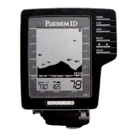
USING THE PLATINUM ID 120 The latch is used to remove the Platinum ID from the swivel mount. To use simply press the bar and lift the unit from the mount. The Connector System cover is used to facilitate mounting of the Platinum ID unit. - Page 21 USING THE PLATINUM ID 120 OPERATING INSTRUCTIONS OPERATING THE PLATINUM ID This section provides complete information on operating the Platinum ID through its front panel controls. You are encouraged to read this information completely as you first learn to use the Platinum ID; doing so will ensure you make the most of its many features and functions.
-
Page 22: Operating Instructions
USING THE PLATINUM ID 120 To adjust any of these, press SELECT until the function you want appears. Each function’s display tells you how to use the arrow buttons and ON-OFF for adjustment; when first using, you should also refer to the following instructions. - Page 23 USING THE PLATINUM ID 120 OPERATING INSTRUCTIONS The three position bottom hardness scale at the bottom of the screen helps differentiate between grass or muddy (soft) bottoms and structure or rock (hard) bottoms. After you adjust any function, the display returns to its full-screen reading.
- Page 24 USING THE PLATINUM ID 120 1. Selecting ID Factory Setting: Fish Symbols ID identifies targets not attached to the bottom and displays them with either a fish symbol or an arch. Three different size fish symbols are used to represent the returned signal strength, a good indicator of fish size.
- Page 25 USING THE PLATINUM ID 120 3. Selecting Sensitivity Factory Setting: +0 The Platinum ID automatically adjusts to the proper amount of sensitivity for conditions (ie depth). You can bias the setting + or – 5 levels to suit your personal taste. Increasing the...
- Page 26 USING THE PLATINUM ID 120 5. Enabling Fish Alarm Factory Setting: OFF The Fish Alarm alerts you with a chirping sound whenever the Platinum ID detects fish (or another object not attached to the bottom). To activate it, select FISH ALARM and press the ON-OFF button.
- Page 27 USING THE PLATINUM ID 120 7. Using Bottom-Lock Factory Setting: OFF Bottom-Lock provides an up-close view like Zoom Range, except that in this case the zoomed view automatically moves up or down to stay on the bottom. To use this feature, select BOTTOM LOCK and press ON-OFF.
- Page 28 USING THE PLATINUM ID 120 9. Setting Depth Range Factory Setting: ON (Automatic) When you turn the Platinum ID on, it finds the bottom, sets the ideal Depth Range, and automatically adjusts the Depth Range (to as much as 120’) as the depth changes.
-
Page 29: Specifications
Operating Frequency Power Requirement Power Cable Length Sensor (standard) Sensor Cone Angle Depth Range Unit Construction Unit Dimensions Display Viewing Area Matrix Configuration SPECIFICATIONS 455KHz 10-16 volts DC 48” SHS6-16 16 degrees 0-15’, 0-30’, 0-60’, 0-120’ High-impact polycarbonate housing 6 ½” W x 6 ¾” H x 1 ½” D Super-twist LCD 3.1”... -
Page 30: Maintenance And Warranty
MAINTENANCE AND WARRANTY MAINTENANCE Your Humminbird fishfinder is designed to provide years of trouble free operation with virtually no maintenance. Follow these simple procedures to ensure your Humminbird continues to deliver top performance. If the unit comes into contact with salt spray simply wipe the affected surfaces with a cloth dampened in fresh water. -
Page 31: Troubleshooting
Repairs should be performed only by authorized Humminbird technicians. Many requests for repair received by Humminbird involve units that do not actually reed repair. These units are returned “no problem found.” If you have a problem with your Humminbird, use the following troubleshooting guide before calling Customer Support or sending your unit in for repair. - Page 32 4. When in very shallow water, I get gaps in the bottom reading and inconsistent digital depth indication. Your Humminbird fishfinder will work reliably in water 2’ (.6m) or deeper. The depth is measured from the transducer, not necessarily from the surface.
- Page 33 7. My unit loses power at high speeds. Most Humminbird fishfinders have over-voltage protection that turns the unit off when input voltage exceeds 20 VDC. Some outboard motors do not effectively regulate the power output of the engine's alternator and can produce voltage in excess of 20 volts when running at high RPMs.
-
Page 34: Warranty
Humminbird reserves the right to perform modifications or improvement on its products without incurring the obligation to install the changes on units previously manufactured, sold, delivered, or serviced. -
Page 35: Service Policy
SERVICE POLICY SERVICE POLICY This Service Policy is valid in the United States only. This applies to Humminbird units returned to our factory in Eufaula, Alabama, and is subject to change without notice. All repair work is performed by factory-trained technicians to meet exacting factory specifications. -
Page 36: Customer Support
CUSTOMER SUPPORT CUSTOMER SUPPORT If you have any questions, call our Humminbird Customer Support Hotline: 1-334-687-0503 Throughout the U.S. and Canada, hours are Monday-Friday, 8:00 a.m. to 5:00 p.m. Central time. If after reading “Troubleshooting” you determine your unit needs factory service, please attach a description of the problem and send it with the unit to the address below.