Table of Contents
Advertisement
Quick Links
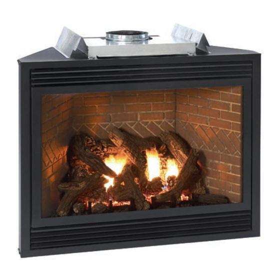
The Tahoe Direct Vent Zero Clearance
Gas Fireplace Heater
Installer: Leave this manual with the appli-
ance.
Consumer: Retain this manual for future refer-
ence.
WARNING: If the information in these instruc-
tions are not followed exactly, a fire or explosion
may result causing property damage, personal
injury or loss of life.
— Do not store or use gasoline or other flamma-
ble vapors and liquids in the vicinity of this or
any other appliance.
— WHAT TO DO IF YOU SMELL GAS
•
Do not try to light any appliance.
•
Do not touch any electrical switch; do not
use any phone in your building.
•
Immediately call your gas supplier from a
neighbor's phone. Follow the gas suppli-
er's instructions.
•
If you cannot reach your gas supplier, call
the fire department.
— Installation and service must be performed by
a qualified installer, service agency or the gas
supplier.
23835-1-0607
INSTALLATION INSTRUCTIONS
OWNER'S MANUAL
UL FILE NO. MH30033
This appliance may be installed in an aftermarket,
permanently located, manufactured home (USA only)
or mobile home, where not prohibited by state or local
codes.
This appliance is only for use with the type of gas
indicated on the rating plate. This appliance is not
convertible for use with other gases, unless a certified
kit is used.
WARNING: If not installed, operated and maintained
in accordance with the manufacturer's instructions,
this product could expose you to substances in fuel or
from fuel combustion which can cause death or seri-
ous illness.
AND
LUXURY DIRECT VENT
GAS FIREPLACE HEATER
MODEL SERIES
MILLIVOLT STANDING PILOT
DVX36FP32CL(N,P)-1
DVX36FP33CL(N,P)-1
DVX42FP32CL(N,P)-1
DVX42FP33CL(N,P)-1
REMOTE RF MODELS
DVX36FP93CL(N,P)-1
DVX42FP93CL(N,P)-1
GAS-FIRED
EFFECTIVE DATE
JUNE 2007
Page 1
Advertisement
Table of Contents

Related Manuals for White Mountain Hearth DVX36FP32CL(N,P)-1


Summary of Contents for White Mountain Hearth DVX36FP32CL(N,P)-1
-
Page 1: Installation Instructions
INSTALLATION INSTRUCTIONS OWNER’S MANUAL The Tahoe Direct Vent Zero Clearance LUXURY DIRECT VENT Gas Fireplace Heater GAS FIREPLACE HEATER MODEL SERIES MILLIVOLT STANDING PILOT DVX36FP32CL(N,P)-1 DVX36FP33CL(N,P)-1 DVX42FP32CL(N,P)-1 DVX42FP33CL(N,P)-1 REMOTE RF MODELS DVX36FP93CL(N,P)-1 DVX42FP93CL(N,P)-1 GAS-FIRED Installer: Leave this manual with the appli- EFFECTIVE DATE ance. -
Page 2: Table Of Contents
TABLE OF CONTENTS Section Page Important Safety Information ........................3 Safety Information for Users of LP Gas ..................... 4 Requirements for Massachusetts ......................... 5 Introduction ..............................6 Specification ..............................7 Fireplace Dimensions ..........................7 Clearances ..............................8 Locating Fireplace ............................8 Gas Supply .............................. -
Page 3: Important Safety Information
IMPORTANT SAFETY INFORMATION Before enclosing the vent pipe assembly, operate the appliance to ensure it is venting properly. DO NOT OPERATE THIS APPLIANCE WITHOUT GLASS FRONT PANEL INSTALLED • If this appliance is installed directly on carpeting, tile • This appliance must not share or be connected to a flue or other combustible material other than wood flooring serving a separate solid-fuel burning appliance. -
Page 4: Safety Information For Users Of Lp Gas
SAFETY INFORMATION FOR USERS OF LP GAS Propane (LP-Gas) is a flammable gas which can cause fires by point with the members of your household. Someday when and explosions. In its natural state, propane is odorless and there may not be a minute to lose, everyone’s safety will depend colorless. -
Page 5: Requirements For Massachusetts
REQUIREMENTS FOR MASSACHUSETTS For all side wall horizontally vented gas fueled equipment installed 3. SIGNAGE. A metal or plastic identification plate shall be in every dwelling, building or structure used in whole or in part permanently mounted to the exterior of the building at a for residential purposes, including those owned or operated by the minimum height of eight (8) feet above grade directly in line Commonwealth and where the side wall exhaust vent termination... -
Page 6: Introduction
INTRODUCTION Instructions to Installer Any alteration of the original design, installed other than as shown in these instructions or use with a type of gas not shown on 1. Installer must leave instruction manual with owner after installation. the rating plate is the responsibility of the person and company 2. -
Page 7: Specification
SPECIFICATIONS DVX36 NAT DVX36 LP DVX42 NAT DVX42 LP Input Btu/hr Maximum 35,000 30,000 37,500 35,000 Btu/hr Minimum 24,000 21,000 26,000 24,000 KWH (Maximum) 10.3 11.0 10.3 (Minimum) Orifice #32 (P-211) 1.65mm (P-250) #31 (P-209) #50 (P-245) Air Shutter Opening 1/4"(6.4mm) FULL OPEN 1/4"... -
Page 8: Clearances
CLEARANCES Mantel Chart (Figure 3) Clearance to Combustibles Back 0" (0 mm) 12” (305mm) 10” (254mm) Side 0" (0 mm) Floor 0" (0 mm) MANTEL Top Stand-off 0" (0 mm) COMBUSTIBLE TRIM AND MANTELS 8” ALLOWED IN SHADED AREA Top Framing Edge 6"... -
Page 9: Gas Supply
GAS SUPPLY Installing a New Main Gas Cock The gas pipeline can be brought in through the right or left side of the appliance. Consult the current National Fuel Gas Code, ANSI Each appliance should have its own manual gas cock. Z223.1 CAN/CGA-B149 (.1 or .2) installation code. -
Page 10: Installation
INSTALLATION Framing and Finishing 1. Choose unit location. 2. Frame in fireplace with a header across the top. It is important to USE OUTER allow for finished face when setting the depth of the frame. (4) FLANGES 3. Attach fireplace to frame using adjustable frame. Preset depth to FOR 1/2”... - Page 11 INSTALLATION (continued) Flush Mount Mantel Installation (Figure 10) The fireplace must extend 3/4" beyond finished wall surface when using a flush mount mantel. Refer to Figure 10 to locate nailing flanges on fireplace sides. Mark and drill two (2) 1/8" holes into fireplace side to mount each nailing flange.
- Page 12 Flush Wall Installation Attention: Cold climate installation recommendation: When installing this unit against a non-insulated exterior wall, it is recommended that the outer walls be insulated to conform to applicable insulation codes. Vent Runs (Figures 14, 15, and 16) In planning the installation for the fireplace, it is necessary to install certain components before the appliance is completely positioned and installed.
-
Page 13: Installation
INSTALLATION (continued) VERTICAL, 90° ELBOW TO CORNER INSTALLATION VERTICAL, 90° ELBOW TO HORIZONTAL OUT THE WALL HORIZONTAL OUT THE WALL “A” WALL FIRESTOP/ 90º ELBOW “A” THIMBLE PIPE LENGTH “B” 6” (152mm) MINIMUM “C” VENT 9” (229mm) “D” MINIMUM VENT CAP WALL FIRESTOP/ THIMBLE Dim. -
Page 14: Venting Fireplace - Top
VENTING FIREPLACE - TOP Venting Graph (Dimensions in Feet) To Use the Vent Graph (Figure 17) 1. Determine the height of the center of the horizontal vent pipe. Using this dimension on the Sidewall Vent Graph, TOP EXIT - VERTICAL AND HORIZONTAL TERMINATION locate the point it intersects with the slanted graph (DIMENSIONS IN FEET) line. - Page 15 VENTING FIREPLACE - TOP (continued) Below Grade Installation When it is not possible to meet the required vent terminal clearances of 12" (305mm) above grade level, a snorkel kit is recommended. It allows installation depth down to 7" (178mm) below grade level. The 7"...
- Page 16 10” (254mm) VENT CAP 12” (305mm) SEE CHART FOR PERMISSIBLE “H” AND “V” DIMENSIONS 9” (229mm) minimum TO SIDE WALL CENTER OF ELBOW STRAIGHT OUT (MINIMUM) Figure 22 Figure 21 MINIMUM HOLE LOCATION DIMENSIONS FOR 3’ THROUGH THE WALL HORIZONTAL INSTALLATIONS (914mm) WITH 90 DEGREE ELBOW OFF TOP OF FIREPLACE MAXIMUM HORIZONTAL...
-
Page 17: Examples - Top Vent Run
EXAMPLES - TOP VENT RUN 24” 24” MINIMUM CLEARANCE TO COMBUSTIBLES Example H2 3ft, H3 1ft = 4ft (90° + 90° + 90°) = 6ft V1 = 21ft H = 10ft V = 21ft Figure 25 Example H2 = 2ft 2 - (90°... -
Page 18: Dvvk-4Re Vent Kit Installation Instructions
DVVK-4RE VENT KIT INSTALLATION INSTRUCTIONS CAUTION: Sharp edges, use protective gloves when NOTE: SPACING FLANGE installing. INSTALLED TO TOPSIDE Tools Needed for Installation: Sheet metal snips 5/16” nut driver Phillips head screwdriver - #2 High temperature sealant or furnace cement rated for continuous use at 1,000 F minimum 11”... - Page 19 DVVK-4RE VENT KIT INSTALLATION INSTRUCTIONS (continued) 7. Remove outside mounting plate with tube attached from wall. Mark and cut the extra length of the 6 5/8” (168mm) diameter VINYL SIDING KIT DV822 tube from the opposite end. Do not crimp or enlarge tube. OUTSIDE MOUNTING 8.
- Page 20 DVVK-4RE VENT KIT INSTALLATION INSTRUCTIONS (continued) Follow correct option according to venting method. Connecting to Rigid Vent System If the air inlet and flue outlet tubes are to be connected to a rigid Connecting Directly to Fireplace venting system (and not directly to the back of the unit), then do If the air inlet and flue outlet tubes are to be connected directly to not use the gasket provided.
-
Page 21: Dvvk-4Fv Direct Vent Termination Kit
DVVK-4FV DIRECT VENT TERMINATION KIT Installation Instructions This termination kit can only be used with Empire Comfort Systems direct vent fireplaces listed for use with DVVK-4FV Vertical Flex Vent Kit. Please review the instructions packaged with your fireplace and verify the fireplace model number. - Page 22 DVVK-4FV DIRECT VENT TERMINATION KIT (cont.) PRE-INSTALLATION INFORMATION: Items Required For Installation: Tools Building Supplies Phillips Screwdriver Framing Materials Hammer Wall Finishing Materials Saw and/or saber saw Caulking Material (Noncombustible) Level Support Strap supplies Measuring Tape Electric Drill and Bits Pliers Square Tin Snips...
- Page 23 DVVK-4FV DIRECT VENT TERMINATION KIT (cont.) Step-By-Step Installation For Flex DV Kit Unpack vent components and check all items for shipping 5. Next, determine the location for the cutout in the roof open- damage. ing. This opening must be large enough to provide a mini- For this venting system to operate as designed it is depen- mum 1”...
- Page 24 DVVK-4FV DIRECT VENT TERMINATION KIT (cont.) 10. With the flex vent assembly and the 48” long hard pipe 13. Now the pre-assembled vent system may be carried to the components laid out on the floor, begin securing these parts roof, then lowered through the roof cutout opening (see step together.
- Page 25 DVVK-4FV DIRECT VENT TERMINATION KIT (cont.) 17. To attach the vent connections at the fireplace, be sure the 7” 21. An additional storm collar band is provided in kit that may be diameter adapter collar has been installed per step 3. Apply used as an attic insulation shield.
- Page 26 DVVK-4FV DIRECT VENT TERMINATION KIT (cont.) VERTICAL TERMINATION STORM COLLAR 4’ LONG RIGID PIPE ROOF FLASHING ADJUSTABLE ROOF JACK ASSEMBLY ROOF EXTERIOR CLEARANCE TO COMBUSTIBLES REQUIRED FROM VENT PIPE CLAMPS AT FLUE & INLET VENT CONNECTIONS ADJUSTABLE STORM COLLAR (USE TO FIRESTOP/THIMBLE KEEP INSULATION OUT OF ASSEMBLY...
-
Page 27: Dvvk-4Fv Direct Vent Termination Kit
DVVK-4FV DIRECT VENT TERMINATION KIT (cont.) Vertical Flex Termination Kit Item Quantity Number Item Description Repair Part No. Supplied 4”/7” Vertical Termination Cap MF100038 Roof Support Kit MF100503 2 Ply Alum Flex 4” Diameter by 6 ft. MF04ALA2F006 2 Ply Alum Flex 7” Diameter by 6 ft. MF07ALA2F006 4”/7”... -
Page 28: Dvvk-4F Flex Vent Instructions - Top Vent Only
DVVK-4F FLEX VENT INSTRUCTIONS The DVVK-4F FLEX VENT KIT includes the following components: • (1) Horizontal Termination Cap • (1) 7" dia. Outer Vent adapter collar • (1) 4-foot section of Flex vent with spacers (4" flue/7" outer • (1) Wall Firestop/Thimble Assembly pipe) •... -
Page 29: Termination Clearances
TERMINATION CLEARANCES Termination clearance for buildings with combustible and noncombustible exteriors. INSIDE CORNER OUTSIDE CORNER RECESSED LOCATION “A” = COMBUSTIBLE 9” (229mm) “F” = COMBUSTIBLE 6” (152mm) = NONCOMBUSTIBLE 2” (51mm) = NONCOMBUSTIBLE 6” (152mm) BALCONY BALCONY WITH PERPENDICULAR SIDE WALL WITH NO SIDE WALL “C”... -
Page 30: Vent Clearances
VENT CLEARANCES AREA WHERE TERMINAL IS NOT PERMITTED VENT TERMINAL AIR SUPPLY INLET Figure 45 *Clearance above grade, veranda, porch, deck or balcony clearance to non-mechanical air supply inlet to building or [*12 inches (30cm) minimum] the combustion air inlet to any other appliance [*12 inches (30cm) minimum for appliances ≤... -
Page 31: Vent System Identification
VENT SYSTEM IDENTIFICATION Installing Vent Components (Figure 46) WALL THIMBLE Begin the vent system installation by installing the first Simpson Duravent VERTICAL component, 90° elbow to the starting collars or straight pipe on the top of TERMINATION (MAXIMUM OF the appliance, then the straight pipe length and then horizontal or vertical THREE 90°... -
Page 32: Venting Framing And Finishing
VENTING FRAMING AND FINISHING Installing Support Brackets (Figure 47) A horizontal pipe support MUST BE used for each 3 feet of horizontal run. The pipe supports should be placed around the pipe and nailed in place to framing members. There MUST BE a 3 inch clearance to combustibles above flue pipe and elbows and 1 inch clearance on both sides and bottom of the flue pipe to combustibles on all horizontal pipe sections and elbows. -
Page 33: Venting Framing And Finishing
VENTING FRAMING AND FINISHING (continued) EXISTING CEILING JOISTS NAILS, 4 REQUIRED CEILING FIRESTOP NEW FRAMING CEILING BELOW Vent Size Vent Size 6 5/8" 10" 10" 6 5/8" 10" 10" 8" 10 1/2" 10 1/2" 8" 10 1/2" 10 1/2" Figure 49 Figure 51 See Horizontal Termination Page 34 and Vertical Termination Pages 35 and 36. -
Page 34: Horizontal Termination
HORIZONTAL TERMINATION NOTE: Termination cap should pass through the wall firestop from the exterior of the building. Adjust the termination cap to its final exterior position on the building. Warning: Termination cap must be positioned so that arrow is pointing up. CUT VINYL SIDING AWAY TO FIT STANDOFF Attach the termination cap with the four wood screws provided. -
Page 35: Dvvk-5F Flex Vent Instructions
DVVK-5F FLEX VENT INSTRUCTIONS The DVVK-5F FLEX VENT KIT includes the following components: • (1) Horizontal Termination Cap • (1) Wall Firestop/Thimble Assembly • (1) 4-foot section of Flex vent with spacers (5" flue/8" • Hardware pack that includes band clamps and screws outer pipe) with flue adapter collar Flex venting can only be installed vertically off of the DVX Series fireplaces. -
Page 36: Vertical Termination
VERTICAL TERMINATION Locate and mark the center point of the venting pipe. Using a nail 2. Remove the cap and shine a flashlight down the vent. Remove on the underside of the roof and drive this nail through this center any bird nests or other foreign material. -
Page 37: Vertical Termination
VERTICAL TERMINATION (continued) Reassembly and Resealing Vent Pipe System Attach vent pipe to inlet and outlet vent adaptor on fireplace, replace horizontal and vertical pipe lengths, elbows and horizontal or vertical termination kit. All vent system components lock into place by sliding the concentric pipe section with four (4) equally spaced interior beads onto the 45°... -
Page 38: Log Identification
LOG IDENTIFICATION REAR BOTTOM LOG (A) REAR TOP LOG (B) Part Number - R9228 Part Number - R9222 BOTTOM LEFT LOG (C) BOTTOM LEFT CENTER LOG (D) Part Number - R9227 Part Number - R9372 BOTTOM RIGHT CENTER LOG (E) BOTTOM RIGHT LOG (F) Part Number - R9225 Part Number - R9229... -
Page 39: Log Placement (13 Log Set)
LOG PLACEMENT (13 LOG SET) Before you begin: If you are installing logs into the DVX36 or 6. Place Bottom Left Log (C) on far left pin of burner. The "lip" DVX42 model then this fireplace is supplied with a set of 13 of the log will hang off the side of the burner. - Page 40 LOG PLACEMENT (13 LOG SET) 9. Place Bottom Right Log (F) on far right pin on the burner. The 12. Place Top Left Log (I) on two left pins on (B) Log. "lip" of the log will hang off the side of the burner. 13.
- Page 41 LOG PLACEMENT (13 LOG SET) 15. Place Front Center Log (L) between third and fourth grates on 18. Replace glass door onto firebox. the burner. The short "Y" branch will point left and the bottom 19. Secure the two glass frame spring clamps at bottom of of the "Y"...
-
Page 42: Log Placement (13 Log Set)
LOG PLACEMENT (13 LOG SET) Figure 62 Figure 63 Log Set Parts List Index Letter Part Number Description R9228 Rear Bottom Log R9222 Rear Top Log R9227 Bottom Left Log R9372 Bottom Left Center Log R9225 Bottom Right Center Log R9229 Bottom Right Log R9223... -
Page 43: Operating Instructions
OPERATING INSTRUCTIONS 750 Millivolt System The OWNER should carefully read and follow these operating The standing pilot (750 millivolt system) is a continuous burning instructions at all times. Lower the door assembly to view the gas pilot. The pilot remains ON even when the main burner is OFF. controls for the fireplace. -
Page 44: Operating Instructions
OPERATING INSTRUCTIONS (continued) STANDING PILOT OPERATING INSTRUCTIONS Installation of Remote Receiver Remote/Off/On Switch Place remote receiver on the floor of fireplace behind the louver The fireplace is equipped with a Remote/OFF/ON switch. A wire as far forward as possible. harness is attached to the Remote/OFF/ON switch. The red, black Attention: The velcro loop and hook are not necessary in this and green (wires) female push-ons attach to the Remote/OFF/ON installation but can be used to secure remote receiver. -
Page 45: Standing Pilot Wiring Diagram
STANDING PILOT WIRING DIAGRAM REMOTE CONTROL RECEIVER (OPTIONAL) THERMOSTAT (OPTIONAL) WALL SWITCH GAS VALVE REMOTE/OFF/ON SWITCH (OPTIONAL) REMOTE CONTROL RECEIVER REMOTE/OFF/ON SWITCH GREEN REMOTE BLACK GREEN THERMOPILE IF ANY OF THE ORIGINAL WIRE AS SUPPLIED WITH THIS UNIT MUST BE REPLACED, IT MUST BE REPLACED WITH NO. -
Page 46: Standing Pilot Lighting Instructions
STANDING PILOT LIGHTING INSTRUCTIONS FOR YOUR SAFETY, READ BEFORE LIGHTING WARNING: If you do not follow these instructions exactly, a fire or explosion may result causing property damage, personal injury or loss of life. A. This appliance has a pilot which must be lighted by hand. •... -
Page 47: Standing Pilot Troubleshooting
STANDING PILOT TROUBLESHOOTING With proper installation and maintenance, your new Direct Vent Gas Fireplace will provide years of trouble-free service. If you do experience a problem, refer to the Trouble Shooting Guide below. This guide will assist a qualified service person in the diagnosis of problems and the corrective action to be taken. -
Page 48: Rf Standing Pilot Operating Instructions
RF STANDING PILOT OPERATING INSTRUCTIONS Features Benefits • Self powered millivolt receiver/valve • No external power or batteries required to operate valve and flame modulation • Thermostat performance • Flame cycles and modulates such that heat output equals heat loss from the room •... -
Page 49: Rf Transmitter Functions
RF TRANSMITTER FUNCTIONS FIRST USE OF TRANSMITTER Status Action Begin communication between transmitter and receiver/valve. Move LOCAL/REMOTE Switch to LOCAL position for at least two seconds; then move switch to the REMOTE position. Transmit unique code. Press Fan or Flame key within 30 seconds. Confirm recognition between transmitter and receiver/valve. -
Page 50: Rf Wiring Diagram
RF WIRING DIAGRAM WIRING DIAGRAM WITH BLOWER Figure 67 Page 50 23835-1-0607... -
Page 51: Rf Standing Pilot Lighting Instructions
RF STANDING PILOT LIGHTING INSTRUCTIONS FOR YOUR SAFETY READ BEFORE LIGHTING WARNING: IF YOU DO NOT FOLLOW THESE INSTRUCTIONS EXACTLY, A FIRE OR EXPLOSION MAY RESULT CAUSING PROPERTY DAMAGE, PERSONAL INJURY, OR LOSS OF LIFE. A. This appliance has a pilot which must be lighted by C. -
Page 52: Maintenance And Service
MAINTENANCE AND SERVICE 3. Under no circumstances should this appliance be operated without Please Note the glass front or with a broken glass front. Replacement of the It is normal for appliances fabricated of steel to give off glass (with gasket) as supplied by the manufacturer should be some expansion and/or contraction noise during the start done by a qualified service person. -
Page 53: Parts View
PARTS VIEW Note: Refer to page 42 when ordering logs. 23835-1-0607 Page 53... -
Page 54: Parts List
PARTS LIST PART NUMBER INDEX DVX36FP33CL DVX36FP93CL DVX42FP33CL DVX42FP93CL DESCRIPTION R9347 R9347 R9348 R9348 INSULATION, TOP SHIELD 23437 23437 23437 23437 TOP SHIELD 23219 23219 23219 23219 TOP STANDOFF (QTY. 2) R7566 R7566 R7567 R7567 VENT ADAPTER R7574 R7574 R7573 R7573 VENT GASKET 10554... -
Page 55: Parts List
PARTS LIST (continued) PART NUMBER INDEX DVX36FP33CL DVX36FP93CL DVX42FP33CL DVX42FP93CL DESCRIPTION R7577 R6114 R7577 R6114 GAS VALVE (NAT) R7578 R6115 R7578 R6115 GAS VALVE (LPG) 17161 17796 17161 17796 GAS VALVE BRACKET 23502 23502 23502 23502 GRATE ASSEMBLY (QTY. 2) 23070 23070 23070... -
Page 56: Fbb4 Optional Variable Speed Blower Installation
FBB4 OPTIONAL VARIABLE SPEED BLOWER INSTALLATION Attention: Install blower assembly before connecting gas inlet 5. Insert blower assembly into interior, bottom of fireplace. supply line Position blower assembly behind gas valve, align notch on back of blower assembly with center screw on fireplace back Note: Junction box on right side of fireplace must be pre-wired at and push blower assembly against fireplace back. -
Page 57: Junction Box Wiring Installation Instructions
FBB4 OPTIONAL VARIABLE SPEED BLOWER INSTALLATION FBB4 B L O W E R A S S E M B LY COMPLETE R7649 FAN CONTROL R4192 SPEED CONTROL KNOB R4186 SPEED CONTROL 110 VOLT AC JUNCTION BOX JUNCTION BOX WIRING INSTALLATION INSTRUCTIONS CAUTION: ALL WIRING SHOULD BE DONE BY A QUALIFIED ELECTRICIAN AND SHALL BE IN COMPLIANCE WITH ALL LOCAL, CITY AND STATE BUILDING CODES. -
Page 58: Accent Lamp
ACCENT LAMP Your Luxury Direct Vent Gas Fireplace comes equipped with our COVER "Accent Lamp." The light has been pre-wired and is controlled from the Rheostat. If in the event the lamp or lens needs to be replaced, follow the instructions below: Unplug the Accent Lamp/transformer from the junction box inside the fireplace. -
Page 59: Accessories
ACCESSORIES The following accessory parts can be obtained from your Empire Comfort Systems dealer. If you need additional information beyond what your dealer can furnish, contact Empire Comfort Systems Inc., Nine Eighteen Freeburg Ave., Belleville, Illinois 62220-2623. DECORATIVE ACCESSORIES Decorative Louver Arch Decorative Louver Leaf Decorative Louver Mission Decorative Door Plain Rectangle... -
Page 60: How To Order Repair Parts
HOW TO ORDER REPAIR PARTS Parts can be ordered only through your service person or dealer. For best results, the service person or dealer should order parts through the distributor. Parts can be shipped directly to the service person/dealer. All parts listed in the Parts List have a Part Number. When ordering parts, first obtain the Model Number from the name plate on your equipment.