Table of Contents
Advertisement
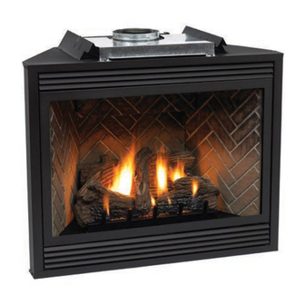
The Tahoe Direct Vent Zero Clearance
Gas Fireplace Heater
WARNING: If the information in this manual
is not followed exactly, a fire or explosion may
result causing property damage, personal
injury or loss of life.
-
Do not store or use gasoline or other
flammable vapors and liquids in the
vicinity of this or any other appliance.
-
WHAT TO DO IF YOU SMELL GAS
● Do not try to light any appliance.
● Do not touch any electrical switch; do
not use any phone in your building.
● Immediately call your gas supplier
from a neighbors phone. Follow the
gas supplier's instructions.
● If you cannot reach your gas supplier,
call the fire department.
-
Installation and service must be
performed by a qualified installer, service
agency, or the gas supplier.
17375-6-0705
INSTALLATION INSTRUCTIONS
OWNER'S MANUAL
DVP42FP3(0,1,2,3)(N,P)-1
DVP48FP3(0,1,2,3)(N,P)-1
UL FILE NO. MH30033
AND
DIRECT VENT
GAS FIREPLACE HEATER
MODEL SERIES
DVP42FP7(0,1,2,3)(N,P)-1
DVP48FP7(0,1,2,3)(N,P)-1
DVP42FP9(0,1,2,3)(N,P)-1
DVP48FP9(0,1,2,3)(N,P)-1
GAS-FIRED
EFFECTIVE DATE
JULY 2005
This appliance may be installed in an aftermarket,
permanently located, manufactured home (USA
only) or mobile home, where not prohibited by
state or local codes.
This appliance is only for use with the type of gas
indicated on the rating plate. This appliance is
not convertible for use with other gases, unless a
certified kit is used.
WARNING: If not installed, operated and main-
tained in accordance with the manufacturer's
instructions, this product could expose you to
substances in fuel or from fuel combustion which
can cause death or serious illness.
(MILLIVOLT STANDING PILOT)
(MILLIVOLT STANDING PILOT)
(INTERMITTENT PILOT)
(INTERMITTENT PILOT)
(REMOTE RF MODELS)
(REMOTE RF MODELS))
Page 1
Advertisement
Table of Contents
Troubleshooting

Related Manuals for White Mountain Hearth DVP42FP7


Summary of Contents for White Mountain Hearth DVP42FP7
-
Page 1: Installation Instructions
17375-6-0705 INSTALLATION INSTRUCTIONS OWNER’S MANUAL GAS FIREPLACE HEATER DVP42FP3(0,1,2,3)(N,P)-1 DVP48FP3(0,1,2,3)(N,P)-1 DVP42FP7(0,1,2,3)(N,P)-1 DVP48FP7(0,1,2,3)(N,P)-1 DVP42FP9(0,1,2,3)(N,P)-1 DVP48FP9(0,1,2,3)(N,P)-1 UL FILE NO. MH30033 This appliance may be installed in an aftermarket, permanently located, manufactured home (USA only) or mobile home, where not prohibited by state or local codes. -
Page 2: Table Of Contents
TABLE OF CONTENTS Section Page Important Safety Information ... 3 Safety Information for Users of LP Gas ... 4 Introduction ... 5 Specifications ... 6 Fireplace Dimensions ... 6 Clearances ... 7 Locating Fireplace ... 7 Gas Supply ... 8 Rear Vent Conversion/Vent Systems ... -
Page 3: Important Safety Information
IMPORTANT SAFETY INFORMATION Before enclosing the vent pipe assembly, operate the appliance to ensure it is venting properly. DO NOT OPERATE THIS APPLIANCE WITHOUT GLASS FRONT PANEL INSTALLED • If this appliance is installed directly on carpeting, tile or other combustible material other than wood flooring the appliance shall be installed on a metal or wood panel extending the full width and depth of the appliance. -
Page 4: Safety Information For Users Of Lp Gas
SAFETY INFORMATION FOR USERS OF LP GAS Propane (LP-Gas) is a flammable gas which can cause fires and explosions. In its natural state, propane is odorless and colorless. You may not know all the following safety precau- tions which can protect both you and your family from an accident. -
Page 5: Introduction
• Installation of any damaged fireplace or vent system component. • Modification of the fireplace or direct vent system. • Installation other than as instructed by Empire Comfort Systems, Inc. • Improper positioning of the logs, glass door or decorative rock. -
Page 6: Specifications
Input Btu/hr Maximum Btu/hr Minimum (millivolt only) KWH (Maximum) (Minimum) NAT. Orifice Air Shutter Opening Orifice Air Shutter Opening Height without standoff Width Depth Gas Inlet Shutoff Valve (Pipe) Venting Options Description DVVK-5TS TOP VENT KIT (HORZ.) - 4½" TO 6" WALL THICKNESS (114.3mm to 152mm) DVVK-5T TOP VENT KIT (HORZ.) - 8"... -
Page 7: Clearances
Clearance to Combustibles Back 0" (0 mm) Side 0" (0 mm) Floor 0" (0 mm) Top Stand-off 0" (0 mm) Top Framing Edge 3" (76 mm) Figure 2 Combustible Material No greeting cards, stockings or ornamentation of any type should be placed on or attached to the fireplace. -
Page 8: Gas Supply
he gas pipeline can be brought in through the right or left side of the appliance. Consult the current National Fuel Gas Code, ANSI Z223.1 CAN/CGA-B149 (.1 or .2) installation code. Recommended Gas Pipe Diameter Pipe Length Schedule 40 Pipe (Feet) Inside Diameter Nat. -
Page 9: Rear Vent Conversion/Vent Systems
VERTICAL VENTING Note : It is recommended that the flue cover plate tab be pulled outward prior to removal. This will ensure that the plate is not accidentally dropped inside the rear air chamber. FLUE COVER PLATE (See note above) INLET VENT COVER PLATE Converting flue take-off to rear venting... -
Page 10: Installation
Framing and Finishing 1. Choose unit location. 2. Frame in fireplace with a header across the top. It is important to allow for finished face when setting the depth of the frame. 3. Attach fireplace to frame using adjustable frame. Preset depth to suit facing material (adjustable to 1/2", 5/8"... - Page 11 Flush Mount Mantel Installation (Figure 10) The fireplace must extend 3/4" beyond finished wall surface when using a flush mount mantel. Refer to Figure 10 to locate nailing flanges on fireplace sides. Mark and drill two (2) 1/8" holes into fireplace side to mount each nailing flange.
- Page 12 Flush Wall Installation FINISHED WALL 3! OF NON-COMBUSTIBLE MATERIAL FRONT TRIM OR NON- COMBUSTIBLE MA TERIAL (INSTALLA TION IS OPTIONAL) JOINT BETWEEN FINISHED WALL AND UNIT SEALED WITH 300° F, 149° C SEALANT MATERIAL (SEALANT IS OPTIONAL) Figure 12 Combustible Surround Installation COMBUSTIBLE SURROUND FINISHED WALL 2 X 4...
- Page 13 HORIZONTAL ONLY, STRAIGHT OUT THE BACK " A" PIPE LENGTH "A" "B" 6"(152mm) 5 1/8"(130mm) to 6 /2"(165mm) 9"(229mm) 8 1/8"(206mm) to 91/2"(241mm) 12"(305mm) 11 1/8"(283mm) to 12 1/2"(317mm) Figure 15 VERTICAL, 90° ELBOW TO HORIZONTAL OUT THE WALL "A" "B"...
-
Page 14: Venting Fireplace-Top Vent
To Use the Vent Graph (Figure 19) 1. Determine the height of the center of the horizontal vent pipe. Using this dimension on the Sidewall Vent Graph, locate the point it intersects with the slanted graph line. 2. From the point of this intersection, draw a vertical line to the bottom of the graph. - Page 15 VENTING FIREPLACE - TOP (continued) Below Grade Installation When it is not possible to meet the required vent terminal clearances of 12" (305mm) above grade level, a snorkel kit is recommended. It allows installation depth down to 7" (178mm) below grade level. The 7"...
- Page 16 C E N T E R Figure 23 MINIMUM HOLE LOCATION DIMENSIONS FOR THROUGH THE WALL HORIZONTAL INSTALLATIONS WITH 90 DEGREE ELBOW OFF TOP OF FIREPLACE FIREPLACE HARD ELBOW DIMENSIONS SERIES "A" "B" DVP42FP 43-1/2" 5" (1105mm) (127mm) DVP48FP 43-1/2" 5"...
- Page 17 EXAMPLES - TOP VENT RUN Figure 27 Figure 26 Figure 28 17375-6-0705 Page 17...
-
Page 18: Venting Fireplace-Rear Vent
VENTING FIREPLACE - REAR To Use the Vent Graph (Figure 29) 1. Determine the height of the center of the horizontal vent pipe. Using this dimension on the Sidewall Vent Graph, locate the point it intersects with the slanted graph line. 2. - Page 19 EXAMPLES - REAR VENT RUN Figure 30 Model DVP42 DVP48 Figure 31 17375-6-0705 Maximum Pipe Length H1 24" 18" Model Maximum Pipe Length H1 DVP42 24" DVP48 6" Figure 32 Figure 33 Page 19...
-
Page 20: Termination Clearances
TERMINATION CLEARANCES Termination clearance for buildings with combustible and noncombustible exteriors. Figure 34 Vertical Sidewall Installations Important! Minimum clearance between vent pipes and combustible materials is three (3") (76mm) on top, and (1") (25mm) on bottom and sides. Important! When vent termination exits through foundation less than 20" below siding outcrop, the vent pipe must flush up with the siding. -
Page 21: Vent Clearances
*Clearance above grade, veranda, porch, deck or balcony [*12 inches (30cm) minimum] clearance to window or door that may be opened [*12 inches (30cm) minimum for appliances < 100,000 Btuh (30kW) clearance to permanently closed window [minimum 12 inches (30cm) recommended to prevent condensation on window] vertical clearance to ventilated soffit located above the terminal within a horizontal distance of 24 inches (60... -
Page 22: Vent System Identification
VENT SYSTEM IDENTIFICATION nstalling Vent Components (Figure 36) Begin the vent system installation by installing the first component, 90° elbow to the starting collars or straight pipe on the top of the appliance, then the straight pipe length and then horizontal or vertical termination kit. -
Page 23: Framing And Finishing
Installing Support Brackets (Figure 37) A horizontal pipe support MUST BE used for each 3 feet of horizontal run. The pipe supports should be placed around the pipe and nailed in place to framing members. There MUST BE a 3 inch clearance to combustibles above 8 inch diameter pipe and elbows and 1 inch clearance on both sides and bottom of the 8 inch dia. -
Page 24: Horizontal Termination
FRAMING AND FINISHING (continued) Figure 39 HORIZONTAL TERMINATION NOTE: Termination cap should pass through the wall firestop from the exterior of the building. Adjust the termination cap to its final exterior position on the building. WARNING: Termination cap must be positioned so that arrow is pointing up. -
Page 25: Dvvk-5F Flex Vent
DVVK-5F FLEX VENT INSTRUCTIONS The DVVK-5F FLEX VENT KIT includes the following components: • (1) Horizontal Termination Cap • (1) 4-foot section of Flex vent with spacers (5" flue/8" outer pipe) with flue adapter collar Flex venting can be installed either vertically or horizontally off of the DVP Series fireplaces. When installing a horizontal vent run from top connections, maintain at least ½"... -
Page 26: Vertical Termination
Locate and mark the center point of the venting pipe. Using a nail on the underside of the roof and drive this nail through this center point. Make the outline of the roof hole around this center point. NOTE: Size of the roof hole dimensions depend on the pitch of the roof. - Page 27 VERTICAL TERMINATION (continued) Reassembly and Resealing Vent Pipe System Attach vent pipe to inlet and outlet vent adaptor on fireplace in either the vertical or horizontal position, replace horizontal and vertical pipe lengths, elbows and horizontal or vertical termination kit. All vent system components lock into place by sliding the concentric pipe section with four (4) equally spaced interior beads onto the appliance collar or previously installed component end with four...
-
Page 28: Log Placement
LOG PLACEMENT (3 LOG SET) Before you begin: If you are installing logs into the DVP42 or DVP48 model then this fireplace is supplied with a set of three ceramic fiber logs. Do not handle these logs with your bare hands. Always wear gloves to prevent skin irritation from ceramic fibers. -
Page 29: Operating Instructions
750 Millivolt System The standing pilot (750 millivolt system) is a continuous burning pilot. The pilot remains ON even when the main burner is OFF. When you ignite the pilot, the thermocouple produces millivolts (electrical current) which energizes the magnet in the gas valve. After 30 seconds to 1 minute time period you can release the gas control knob and the pilot will stay ON. - Page 30 OPERATING INSTRUCTIONS (continued) STANDING PILOT OPERATING INSTRUCTIONS REMOTE/OFF/ON Switch The fireplace is equipped with a REMOTE/OFF/ON switch. A wire harness is attached to the REMOTE/OFF/ON switch. The red, black and green (wires) female push-ons attach to the RE- MOTE/OFF/ON switch. At the opposite end of the wire harness, the black and green (wires) female push-ons attach to the gas valve.
-
Page 31: Wiring Diagram-Standing Pilot
STANDING PILOT WIRING DIAGRAM (OPTIONAL) THERMOSTAT (OPTIONAL) WALL SWITCH Figure 52 17375-6-0705 Page 31... -
Page 32: Lighting Instructions-Standing Pilot
STANDING PILOT LIGHTING INSTRUCTIONS FOR YOUR SAFETY READ BEFORE LIGHTING WARNING: If you do not follow these instructions exactly, a fire or explosion may result causing property damage, personal injury or loss of life. A. This appliance has a pilot which must be lighted by hand. When lighting the pilot, follow these instructions exactly. -
Page 33: Troubleshooting-Standing Pilot
STANDING PILOT TROUBLESHOOTING With proper installation and maintenance, your new Direct Vent Gas Fireplace will provide years of trouble-free service. If you do experience a problem, refer to the Trouble Shooting Guide below. This guide will assist a qualified service person in the diagnosis of problems and the corrective action to be taken. -
Page 34: Intermittent Pilot Operating Instructions
INTERMITTENT PILOT OPERATING INSTRUCTIONS The intermittent pilot (120/24 volt system) is ON when the main burner is ON. When the main burner is OFF the intermittent pilot is OFF. The pilot flame should envelop 3/8 to 1/2 inch (10 to 13mm) of the tip of the flame rod. -
Page 35: Intermittent Pilot Lighting Instruction
INTERMITTENT PILOT LIGHTING INSTRUCTIONS FOR YOUR SAFETY READ BEFORE LIGHTING WARNING: If you do not follow these instructions exactly, a fire or explosion may result causing property damage, personal injury or loss of life. A. This appliance is equipped with an ignition device which automatically lights the pilot. -
Page 36: Intermittent Pilot Troubleshooting
The 24 volt system. Type of gas being used and that shown on the rating label. The Service Department at Empire Comfort Systems, Inc. may be contacted to assist in servicing furnace. Servicing the Pilot and Main Burners, Pilot Orifice, and Main Burner Orifices: Disconnect the gas supply at the inlet to the... - Page 37 INTERMITTENT PILOT TROUBLESHOOTING Safety Lockout S8600H provides 100 percent shutoff, or safety lockout. A timer starts timing the moment the trial for ignition starts. Ignition spark continues only until the timed trial for ignition period ends. Then the module goes into safety lockout. Lockout de-energizes the first main valve operator and closes the first main valve in the gas control, stopping pilot gas flow.
- Page 38 Important 1. The following service procedures are provided as a general guide. 2. Meter readings between gas control and ignition module must be taken within the trial for ignition period. Once the igni- tion module locks out, the system must be reset by setting the thermostat down for at least one minute before continuing.
- Page 39 INTERMITTENT PILOT TROUBLESHOOTING (continued) START Turn gas supply off Turn thermostat to call for heat. Power to module. (24 VAC nominal) Spark across ignitor/sensor gap. Turn gas supply on. Pilot burner lights? Spark stops when pilot is lit? Main burner lights? System runs until call for heat ends? Ye s...
-
Page 40: Rf Standing Pilot Operating Instructions
RF STANDING PILOT OPERATING INSTRUCTIONS Features • Self powered millivolt receiver/valve • Thermostat performance • Auto mode • Self powered millivolt control • Integrated Valve Electronics • Failure analysis • Pilotstat interlock • F or C temperature units Please review and retain the instructions included with the RF Transmitter. It provides additional information and details concerning the operational procedures and functions for the RF Remote Control. -
Page 41: Rf Transmitter Functions
RF TRANSMITTER FUNCTIONS FIRST USE OF TRANSMITTER Status Begin communication between transmitter and receiver/valve. Transmit unique code. Confirm recognition between transmitter and receiver/valve. Chose Remote or Local operation. Operation in the Remote Position AUTO Mode With the control in the AUTO mode, the flame in the main burner will turn on, off, or change height based on the heat needed to maintain the set temperature. -
Page 42: Rf Wiring Diagram
RF WIRING DIAGRAM WIRING DIAGRAM WITH BLOWER Figure 56 Page 42 17375-6-0705... -
Page 43: Rf Standing Pilot Lighting Instructions
RF STANDING PILOT LIGHTING INSTRUCTIONS TANDING PILOT LIGHTING INSTRUCTIONS 17375-6-0705 Page 43... -
Page 44: Maintenance And Service
MAINTENANCE AND SERVICE PLEASE NOTE It is normal for appliances fabricated of steel to give off some expansion and/or contraction noise during the start up or cool down cycle. Similar noises are found with your furnace heat exchanger or car engine. It is not unusual for your gas fireplace to give off some odor the first time it is burned. -
Page 45: Parts View
PARTS VIEW 17375-6-0705 Page 45... -
Page 46: Parts List
INDEX NO. PART NUMBER DVP42 R-7654 17426 R-7567 R-7573 17363 M170 17142 R-7575 17430 R-7574 17247 10554 17162 R-3492 17357 17445 17804 17381 17187 17190 17188 R-7532 R-7533 R-5747 R-5748 R-6116 R-6117 M173 11269 P200 P203 P185+ R-5676 11499 11377 17370 17368 17369... -
Page 47: Fbb4 Optional Variable Speed Blower Installation
FBB4 OPTIONAL VARIABLE SPEED BLOWER INSTALLATION Attention: Install blower assembly before connecting gas inlet supply line Note: Junction box on right side of fireplace must be pre-wired at time of fireplace installation for use with blower assembly. It is recommended that an ON/OFF wall switch be installed that will activate the power supply to the furnace by a qualified electrician. -
Page 48: Fbb4 Optional Variable Speed Blower Installation
FBB4 OPTIONAL VARIABLE SPEED BLOWER INSTALLATION Page 48 FBB4 R7649 R4192 R4186 110 VOLT AC JUNCTION BOX BLOWER ASSEMBLY COMPLETE FAN CONTROL SPEED CONTROL KNOB SPEED CONTROL 17375-6-0705... -
Page 49: Junction Box Wiring Installation Instruction
JUNCTION BOX WIRING INSTALLATION INSTRUCTIONS CAUTION: ALL WIRING SHOULD BE DONE BY A QUALIFIED ELECTRICIAN AND SHALL BE IN COMPLIANCE WITH ALL LOCAL, CITY AND STATE BUILDING CODES. BEFORE MAKING THE ELECTRICAL CONNECTION, MAKE SURE THAT MAIN POWER SUPPLY IS DISCONNECTED. THE APPLIANCE, WHEN INSTALLED, MUST BE ELECTRICALLY GROUNDED IN ACCORDANCE WITH LOCAL CODES OR, IN THE ABSENCE OF LOCAL CODES, WITH THE NATIONAL ELECTRICAL CODE ANSI/NFPA 70 (LATEST EDITION). -
Page 50: Accessories
The following accessory parts can be obtained from your Empire Comfort Systems dealer. If you need additional information beyond what your dealer can furnish, contact Empire Comfort Systems Inc., Nine Eighteen Freeburg Ave., Belleville, Illinois 62220-2623. Accessory Fan Kit Simulated Brick Panels... -
Page 51: How To Order Repair Parts
Do not order bolts, screws, washers or nuts. They are standard hardware items and can be purchased at any local hardware store. Shipments contingent upon strikes, fires and all causes beyond our control. Empire Comfort Systems, Inc. Nine Eighteen Freeburg Ave. Belleville, Illinois 62222-2623 17375-6-0705... - Page 52 Empire Comfort Systems, Inc. Nine Eighteen Freeburg Ave. Belleville, Illinois 62220-2623 Page 52 SERVICE NOTES E-MAIL: info@empirecomfort.com WEB SITE: www.empirecomfort.com PH: 618-233-7420 PH: 800-851-3153 FAX: 618-233-7097 FAX: 800-443-8648 17375-6-0705...