Vermont Castings SDDVTCB Homeowner's Installation And Operating Manual
Direct vent/natural vent gas heater sddvt series/sddvtc series
Hide thumbs
Also See for SDDVTCB:
- Installation and operating manual (52 pages) ,
- Homeowner's installation and operating manual (52 pages) ,
- Homeowner's installation and operating manual (52 pages)
Table of Contents
Advertisement
Quick Links
INSTALLER / CONSUMER
SAFETY INFORMATION
PLEASE READ THIS MANUAL
BEFORE INSTALLING AND USING
APPLIANCE.
WARNING!
IF THE INFORMATION IN THIS
MANUAL IS NOT FOLLOWED
EXACTLY, A FIRE OR EXPLOSION
MAY RESULT CAUSING
PROPERTY DAMAGE, PERSONAL
INJURY OR LOSS OF LIFE.
FOR YOUR SAFETY
Installation and service must be
performed by a qualified installer, service
agency or the gas suppler.
WHAT TO DO IF YOU SMELL GAS:
• Do not try to light any appliance.
• Do not touch any electric switch; do
not use any phone in your building.
• Immediately call your gas supplier from
your neighbor's phone. Follow the gas
supplier's instructions.
• If you cannot reach your gas supplier,
call the fire department.
DO NOT STORE OR USE
GASOLINE OR OTHER
FLAMMABLE VAPORS AND
LIQUIDS IN THE VICINITY OF THIS
OR ANY OTHER APPLIANCE.
This appliance may be installed in an after
market permanently located manufactured
(mobile) home where not prohibited by
local codes.
This appliance is only for use with the
type of gas indicated on the rating plate.
This appliance is not convertible for use
with other gases unless a certified kit is
used.
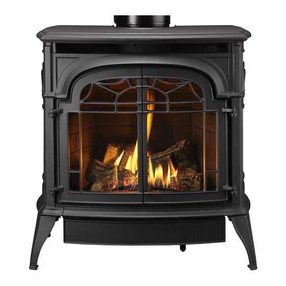
Stardance
Direct Vent/Natural Vent
Gas Heater
Models:
SDDVT Series: SDDVTCB, SDDVTEB, SDDVTBS,
SDDVTBD, SDDVTBM
SDDVTC Series: SDDVTCSCB, SDDVTCSEB,
SDDVTCSBS, SDDVTCSBD, SDDVTCSBM
Homeowner's Installation
and Operating Manual
INSTALLER: Leave this manual with the appliance.
CONSUMER: Retain this manual for future reference.
®
12734
Stardance Dv
cover
8/07
C E RT I F I E D
30004968 7/13 Rev. 9
Advertisement
Table of Contents
Troubleshooting

Related Manuals for Vermont Castings SDDVTCB


Summary of Contents for Vermont Castings SDDVTCB
- Page 1 • If you cannot reach your gas supplier, call the fire department. DO NOT STORE OR USE GASOLINE OR OTHER Models: FLAMMABLE VAPORS AND SDDVT Series: SDDVTCB, SDDVTEB, SDDVTBS, LIQUIDS IN THE VICINITY OF THIS SDDVTBD, SDDVTBM OR ANY OTHER APPLIANCE. 12734 SDDVTC Series: SDDVTCSCB, SDDVTCSEB,...
-
Page 2: Table Of Contents
Table of Contents PLEASE READ THE INSTALLATION & OPERATING INSTRUCTIONS BEFORE USING APPLIANCE. Thank you and congratulations on your purchase of a Vermont Castings stove. IMPORTANT: Read all instructions and warnings carefully before starting installation. Failure to follow these instructions may result in a possible fire hazard and will void the warranty. -
Page 3: General Information
General Information The Stardance Direct Vent/Natural Vent Room Heater, Model The Stardance Direct Vent/Natural Vent Room Heater, when in- Nos. SDDVTCB, SDDVTEB, SDDVTBS, SDDVTBD, SDDVTBM, stalled, must be electrically grounded in accordance with local SDDVTCSCB, SDDVTCSEB, SDDVTCSBS, SDDVTCSBD, SD- codes or, in the absence of local codes, with the National Electri-... -
Page 4: Operating Installation Requirements For The Commonwealth Of Massachusetts
Stardance® Direct Vent/Natural Vent Gas Heater Installation Requirements Requirements for the Commonwealth of Inspection Massachusetts The state or local gas inspector of the side wall horizontally vented gas fueled equipment shall not approve the All gas fitting and installation of this heater shall only be installation unless, upon inspection, the inspector observes done by a licensed gas fitter or licensed plumber. - Page 5 Natural Vent unit in the field. If a Natural Vent heater is desired, the Vermont Castings Z31B00 FSDHAG Draft Hood must be directly installed to the top of the unit according to the installation instructions. The Draft Hood Adapter is available in the 7FSDHASK stove kit or as a separate item.
-
Page 6: Installation Requirements
Stardance® Direct Vent/Natural Vent Gas Heater Installation Requirements The installation must conform with local codes or, in the absence of local codes, with the National Fuel Gas Code, ANSI Z223.1/NFPA 54 - latest edition. (EXCEPTION: Do not derate this appliance for altitude. Maintain the mani- fold pressure at 3.5 inches w.c. -
Page 7: Parallel & Corner Installation
Direct Vent Only Natural Vent Effective Minimum ST128b Wall Thimble 56” (1480 mm) Stove Clearances: A: 4” (102 mm) (Vermont Castings Group Pipe) ST131b B: 4” (102 mm) Centerline 52” (1378 mm) (DuraVent Pipe) ST131b Stardance Pipe Centerlines: C: 15Z\x” (395 mm) -
Page 8: Gas Specifications
90° Elbows ANSI Z21.88-2009 / CSA 2.33-2009 Vented Gas Fireplace Heaters The installation of your Vermont Castings stove must conform with local codes, or in the absence of local ST134a codes, with the National Fuel Gas Code ANSI Z223.1/ FDV28 NFPA 54 - latest edition, or CSA B149.1 Installation... -
Page 9: Vertical Termination - Direct Vent Only
Stardance® Direct Vent/Natural Vent Gas Heater Restrictor Plate Adjustment Vertical Termination - Direct Vent ONLY for Extended Pipe Runs A vertical vent system must terminate no less than 8’ (2.44 m) and no more than 40’ (12 m) above the appliance flue The Stardance stove is shipped with a restrictor plate in collar. -
Page 10: Vent Termination Clearances
Some of the most com- mon clearances to keep in mind are shown in Figure 11. • Vermont Castings Group does not require any opening for inspection of vent pipe. Important: All vent clearances must be maintained. -
Page 11: General Venting Information - Termination Location
2. The special venting system used on Direct Vent units are certified as part of the appliance, with clearances tested and approved by the listing agency. 3. Vermont Castings Group assumes no responsibility for the improper performance of the appliance when the venting system does not meet these requirements. -
Page 12: Termination Clearances
Stardance® Direct Vent/Natural Vent Gas Heater Termination Clearances Termination clearances for buildings with combustible and noncombustible exteriors. Inside Corner Alcove Applications* Outside Corner Combustible 6" (152 mm) Combustible 6" (152 mm) Noncombustible 2" (51 mm) Noncombustible 2" (51 mm) Balcony - Balcony - with no side wall with perpendicular side wall... -
Page 13: Venting Requirements And Options - Direct Vent Only
6” Straight, Blk. 4DT-06B parts are available from DuraVent Corporation, Selkirk 9” Straight, Blk. 4DT-09B Corporation or your Vermont Castings Dealer. 4” - 10” Adjustable Straight Section Blk. 4DT-AJ12B See Figure 4 for dimensions relevant to the standard min- 12” Straight, Blk. - Page 14 Stardance® Direct Vent/Natural Vent Gas Heater Vermont Castings Group Vent Components Twist Lock 12” Straight Pipe (CG) 7TFSDVP12 The following kits are available to meet the needs of most (1) 12” Non-adjustable Pipe Twist Lock 12”-18” Straight Pipe (CG) 7TFSDVP1218 installations.
-
Page 15: Assembly
Stardance® Direct Vent/Natural Vent Gas Heater • Insert the rheostat through the hole in the back of Install the Optional Fan - SDDVT Series the left side of the valve bracket, aligning the locator If you are installing the optional convection Fan Kit #2767 pin with the smaller hole in that bracket. -
Page 16: Venting System Assembly - Direct Vent
CSA B149.1 installation code. Install the Vent Adapter Pipe ST212a (Vermont Castings Group Vent Components) Fig. 19 Attach inner assembly to flue collar. 1. Attach Inner Starter Pipe, (found in the parts bag), to the next section of inner pipe. -
Page 17: Side Wall Termination Assembly
• Connect a standard Direct-Temp pipe length (do not 4. For Vermont Castings Group Vent Pipe only: If nec- use an adjustable length in this application) a minimum essary, measure to determine the vertical length (X) of of 1Z\x” over the flue outlet. The outside of the Direct-... - Page 18 Sleeve #8 Sheet Metal Screws ST215 Fig. 26 Measure the horizontal length. 10. For both Vermont Castings Group and DuraVent Systems: Install the vent terminal. (Fig. 28) Apply ST215 high temperature sealant one inch from the ends of Firestop measure thru wall the inner and outer collars.
-
Page 19: Vent Termination Below Grade
3. Cut the opening: 12/6/99 djt 1. Establish the vent hole through the wall. Vermont Castings Group System: 2. Remove soil to a depth of approximately 16” (400mm) below the base of the snorkel. Install a window well 9C\₈” x 9C\₈” (240 x 240mm) (not supplied). -
Page 20: Selkirk Direct-Temp Metalbestos Direct Vent System
Stardance® Direct Vent/Natural Vent Gas Heater Selkirk Direct-Temp Metalbestos Direct Vent #7DVAIS System Attic Insulation Shield Installation Instructions 1. Determine whether the length of pipe fits the appliance outlet by attempting to engage the parts. If the parts engage smoothly, proceed to Step 2. If obstructions, interference or loose fit is noted, contact the appliance #7DVFS manufacturer or Selkirk Metalbestos with the dimen-... - Page 21 Stardance® Direct Vent/Natural Vent Gas Heater Gasket Outlet End Inlet End Lock Tab To Termination To Appliance ST922 Fig. 33 Joint connection. Horizontal Termination (HC) Trim Plate (TP) (Required if Wall Vent Termination (VC) Thimble is not used) Pipe Length Wall Thimble (WT) Storm Collar (SC) (Optional)
-
Page 22: Horizontal Installation
Stardance® Direct Vent/Natural Vent Gas Heater Supporting DIRECT-TEMP: Vertical Support Offsets: Vertical installations can be supported by two methods: If any offsets are necessary in the vertical system, an Off- set Support (OS) should be installed directly above the Ceiling Support (CS) (used in flat ceiling installation) upper elbow of the offset. - Page 23 Stardance® Direct Vent/Natural Vent Gas Heater NOTE: As a general rule, the wall thimble is optional in the U.S. However, there may be some manufacturers that require it. Contact the appliance manufacturer for infor- mation if uncertain. When installed in Canada, a wall Firestop (FS) thimble is required on all installations in which the Placed on Top...
-
Page 24: Vertical Installation
Stardance® Direct Vent/Natural Vent Gas Heater Horizontal Termination Vertical Termination Storm Collar Approved Silicone Sealant Here Flashing Offset Support Collar ST931 Fig. 41 Horizontal termination. Firestop Spacer Vinyl Siding Standoff Ceiling Sup- Horizontal Termination port Plate Ceiling Support Collar ST932 Fig. -
Page 25: Venting System Assembly - Natural Vent
Direct Vent Heater. It may be converted to a Natural Vent tion height and with the appliance manufacturer’s installa- heater by installing the Vermont Castings Model Z31B00 tion instructions. (Fig. 44) FSDHAG Draft Hood Adapter. -
Page 26: Install The Vent Pipe
Stardance® Direct Vent/Natural Vent Gas Heater For U.S. installations: The venting system must conform with local codes and/or the current National Fuel Gas Code, ANSI Z22.1. Vermont Castings Decorative Group Direct Vent 7” Pipe For Canadian installations: The venting system must... - Page 27 Stardance® Direct Vent/Natural Vent Gas Heater Pilot Assembly Figure 47 Raised Notch Raised Notch LG497 Figure 48 3. Install the left log by mat- ing the hole on the bot- tom of the log with the pin in the ember bed. Left Log (Fig.
-
Page 28: Connect Gas Supply Line
Burner Information The appliance must only use the gas specified on the rating plate, unless converted using a Vermont Castings ON/OFF Switch or ST315 Fuel Conversion Kit. To convert from Natural Gas to LP... -
Page 29: Thermostat Connection (Optional)
Stardance® Direct Vent/Natural Vent Gas Heater Install the Front Plate Thermostat Connection (optional) Hold the front plate by the window bars and lift it into posi- Use only a thermostat rated for 500 millivolts. tion, engaging the two steel tabs on the top corners be- Check the table below for the appropriate gauge thermo- hind the adjacent bosses in the side plates. -
Page 30: Operation
Stardance® Direct Vent/Natural Vent Gas Heater Operation Pilot and Burner Inspection Each time you light your heater check that the pilot flame and burner flame patterns are as shown in Figure 56. If flame patterns are incorrect, turn the heater off. Contact your dealer or a qualified gas technician for assistance. -
Page 31: Lighting And Operating Instructions
Stardance® Direct Vent/Natural Vent Gas Heater Lighting and Operating Instructions FOR YOUR SAFETY READ BEFORE LIGHTING WARNING:If you do not follow these instructions exactly, a fire or explosion may result causing property damage, personal injury or loss of life. A. This heater has a pilot which must be lit manually. When Follow the gas supplier’s instructions. -
Page 32: Troubleshooting - Sit Nova 820 (Sddvt Series)
Stardance® Direct Vent/Natural Vent Gas Heater Troubleshooting the Gas Control System (SDDVT Series) SIT NOVA 820 MILLIVOLT VALVE NOTE: Before trouble shooting the gas control system, be sure external gas shut off is in the “On” position. Symptom Possible Causes Corrective Action 1. -
Page 33: Instructions For Rcsitea (Sddvtcs Series)
Stardance® Direct Vent/Natural Vent Gas Heater Instructions for RCSITEA 3. To check, press either the ON or OFF button on the transmitter and the receiver indicator light will blink. If SDDVTCS Series not, repeat Step 2. CAUTION: The RCSITEA is only certified for use on vent- 4. - Page 34 Stardance® Direct Vent/Natural Vent Gas Heater 4. There will be a slight delay in the response of the unit Initial Startup (on/off) to a temperature. Room temperature is moni- Figure 60 tored every three (3) minutes. 1. After initial power up or °F 5.
- Page 35 Stardance® Direct Vent/Natural Vent Gas Heater Transmitter Thermal Shutdown 2. Use the ON / ▲ button to set the desired On Delay Figure 68 Time from 0 to 15 min- 1. If transmitter measures a utes. room temperature exceed- 3. Use the OFF / ▼ button ing 99°...
-
Page 36: Troubleshooting For Rcsitea
Stardance® Direct Vent/Natural Vent Gas Heater Testing Remote Control System 1. Light the gas appliance following the lighting instruc- tions on Page xx. Confirm the pilot light is on; it must be in operation for the remote control to operate the main gas valve and blower. -
Page 37: Fuel Conversion Instructions
Stardance® Direct Vent/Natural Vent Gas Heater Fuel Conversion Instructions 4. Insert a 5/32” WARNING! This conversion kit shall be installed or 4 mm Allen by a qualified service agency in accordance with wrench into the the manufacturer’s instructions and all applicable Figure 70 hexagonal key- Figure... - Page 38 Stardance® Direct Vent/Natural Vent Gas Heater 3. Remove pilot hood by lifting up. (Fig. 77) Do not re- SDDVTCS Series Models move snap ring to remove pilot hood. NOTE: It is not 1. Using the TORX T20 bit remove and discard the three necessary to remove the pilot tube for conversion.
- Page 39 Stardance® Direct Vent/Natural Vent Gas Heater Orifice Orifice Venturi Bracket Bracket Orifice Air Shutter Bracket CO142 Fig. 82 The air shutter setting is 1/2” (13 mm) from the orifice Pem Studs bracket to the edge of the air shutter. ST919 1.
-
Page 40: Maintenance
Glass Replacement VACUUM TO CLEAN THE LOGS OR BURNER. 6. Replace the glass panel and frame assembly. Replace glass only with Vermont Castings Group ap- 7. Replace the Stove Front. proved parts. Refer to Page 44 for Replacement Parts. Refer to Figures 83 & 84 for removal of the damaged Care of Cast Iron glass frame. -
Page 41: Gasket Replacement
Do not use your stove if the flame pattern differs from that replaced. New gasket is available from your dealer. shown here. Contact your Vermont Castings dealer or a Shut off the gas supply and allow the stove to cool. Wear qualified technician for help. -
Page 42: Wiring Diagrams
Stardance® Direct Vent/Natural Vent Gas Heater Wiring Diagrams - SDDVT On/Off Switch POWER CORD Wiring TP/TH Millivolt Gas Valve Black Chassis ST124b Ground Thermostat Thermostat Optional Thermostat (Optional) (Optional) Wiring St124b FAN JUNCTION BOX on/off/switch TP/TH wiring Millivolt 1/11/00 djt Gas Valve Strain Relief Black... - Page 43 Stardance® Direct Vent/Natural Vent Gas Heater Wiring Diagrams - SDDVTCS Black 120V AC Adapter Black T H mV Valve Receiver T P / T H 120V AC Plug Female Male SIT HI / LO 120V AC Valve Blower ST1091a Fig. 90 SIT Hi/Lo blower schematic. ST1090 120V AC Plug for Receiver SIT valve wiring...
-
Page 44: Replacement Parts
27a,b 22 23 21 24 25 26 Vermont Castings Group reserves the right to make changes in design, materials, specifications, prices and discontinue colors and products at any time, without notice. Stardance Direct Vent/Natural Vent Gas Heater 4968 Stardance Models: SDDVT/TCS parts... - Page 45 Stardance® Direct Vent/Natural Vent Gas Heater Stardance Direct Vent/Natural Vent Gas Heater SDDVT Series: SDDVTCB, SDDVTEB, SDDVTBS, SDDVTBD, SDDVTBM SDDVTCS Series: SDDVTCSCB, SDDVTCSEB, SDDVTCSBS, SDDVTCSBD, SDDVTCSBM Ref. Description SDDVT/SDDVTCS Log Set - Complete 20012551 Log Rear 20012546 Log Right 20012548...
- Page 46 Stardance® Direct Vent/Natural Vent Gas Heater Stardance Direct Vent/Natural Vent Gas Heater SDDVT Series: SDDVTCB, SDDVTEB, SDDVTBS, SDDVTBD, SDDVTBM SDDVTCS Series: SDDVTCSCB, SDDVTCSEB, SDDVTCSBS, SDDVTCSBD, SDDVTCSBM Ref. Description SDDVT/SDDVTCS Sensor 1450 CMG-8184-0032 (for use with FSDHAG only) 10002013 Wiring Harness...
- Page 47 Stardance® Direct Vent/Natural Vent Gas Heater Stardance Direct Vent/Natural Vent Gas Heater SDDVT Series: SDDVTCB, SDDVTEB, SDDVTBS, SDDVTBD, SDDVTBM SDDVTCS Series: SDDVTCSCB, SDDVTCSEB, SDDVTCSBS, SDDVTCSBD, SDDVTCSBM Shell Enamel Part Numbers Color Left End Right End Front OP Left Door* Right Door* Left Door** Right Door**...
-
Page 48: Optional Accessories
Stardance® Direct Vent/Natural Vent Gas Heater Optional Accessories Fan Kit - STDDVT Screen Kit FK26 Fan An optional screen, S30SK, for use with the operable doors is available to allow the doors to be left in the open The FK26 fan helps distribute heated air from within position. - Page 49 Stardance® Direct Vent/Natural Vent Gas Heater 30004968...
- Page 50 Stardance® Direct Vent/Natural Vent Gas Heater 30004968...
-
Page 51: Warranty
LIMITED LIFETIME WARRANTY Stardance® Direct Vent/Natural Vent Gas Heater PRODUCT COVERED BY THIS WARRANTY All Vermont Castings brand gas stoves, gas inserts, and gas fireplaces installed in the United States of America or Canada. LIMITED LIFETIME WARRANTY • Any part or component replaced under the provisions of this... - Page 52 SDDVT Series 64.6 66.5 SDDVTCS Series 64.6 66.5 Recherchez dans la brochure les caractéristique de rendement énergétique de foyer au gaz Énerguide Based on CSA P.4.1-09 Selon CSA P.4.1-09 Vermont Castings Group 149 Cleveland Drive • Paris, Kentucky 40361 www.vermontcastingsgroup.com...