Advertisement
MAINTENANCE INSTRUCTIONS
MAINTENANCE INSTRUCTIONS
MAINTENANCE INSTRUCTIONS
MAINTENANCE INSTRUCTIONS
MAINTENANCE INSTRUCTIONS
PEGASUS F2
PEGASUS F2
PEGASUS F2
PEGASUS F2
PEGASUS F2
GAS-FIRED CAST-IRON BOILERS
GAS-FIRED CAST-IRON BOILERS
GAS-FIRED CAST-IRON BOILERS
GAS-FIRED CAST-IRON BOILERS
GAS-FIRED CAST-IRON BOILERS
WITH ELECTRONIC IGNITION
WITH ELECTRONIC IGNITION
WITH ELECTRONIC IGNITION
WITH ELECTRONIC IGNITION
WITH ELECTRONIC IGNITION
AND FLAME RECTIFICATION MONITORING
AND FLAME RECTIFICATION MONITORING
AND FLAME RECTIFICATION MONITORING
AND FLAME RECTIFICATION MONITORING
AND FLAME RECTIFICATION MONITORING
INSTALLATION AND
INSTALLATION AND
INSTALLATION AND
INSTALLATION AND
INSTALLATION AND
Models 51 - 68 - 85 - 102
Models 51 - 68 - 85 - 102
Models 51 - 68 - 85 - 102
Models 51 - 68 - 85 - 102
Models 51 - 68 - 85 - 102
Advertisement
Table of Contents

Related Manuals for Ferroli PEGASUS F2 51


Summary of Contents for Ferroli PEGASUS F2 51
- Page 1 INSTALLATION AND INSTALLATION AND INSTALLATION AND INSTALLATION AND INSTALLATION AND MAINTENANCE INSTRUCTIONS MAINTENANCE INSTRUCTIONS MAINTENANCE INSTRUCTIONS MAINTENANCE INSTRUCTIONS MAINTENANCE INSTRUCTIONS PEGASUS F2 PEGASUS F2 PEGASUS F2 PEGASUS F2 PEGASUS F2 GAS-FIRED CAST-IRON BOILERS GAS-FIRED CAST-IRON BOILERS GAS-FIRED CAST-IRON BOILERS GAS-FIRED CAST-IRON BOILERS GAS-FIRED CAST-IRON BOILERS WITH ELECTRONIC IGNITION WITH ELECTRONIC IGNITION...
-
Page 2: Table Of Contents
Contents Contents Contents Contents Contents 1. 1. 1. 1. 1. General technical data ......................3 2. 2. 2. 2. 2. Dimensions and technical data ....................3 3. 3. 3. 3. 3. Boiler installation ........................7 4. 4. 4. 4. 4. Wiring and connection diagrams....................8 5. -
Page 3: General Technical Data
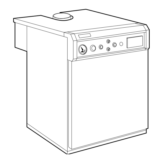
1. GENERAL TECHNICAL DATA 1. GENERAL TECHNICAL DATA 1. GENERAL TECHNICAL DATA 1. GENERAL TECHNICAL DATA 1. GENERAL TECHNICAL DATA 1.01 1.01 1.01 1.01 1.01 Introduction Introduction Introduction Introduction Introduction The Pegasus F2 Pegasus F2 Pegasus F2 Pegasus F2, with CE approval, is designed for use with natural gas (G20) or LPG (G31) for indirect Pegasus F2 central heating and hot water. - Page 4 The boiler is designed to operate with a flow temperature of 82°C and a maximum ∆t of 20°C. HEAT HEAT INPUT HEAT INPUT NUMBER OF MODEL OUTPUT (NETT) (GROSS) SECTIONS Pegasus F2 51 62,2 Pegasus F2 68 74,8 Pegasus F2 85 93,5 103,8 Pegasus F2 102 124,3 WEIGHT...
- Page 5 2.03 2.03 2.03 Main components Main components Main components Main components 2.03 2.03 Main components Front view of the boiler without front casing Front view of the boiler without front casing Front view of the boiler without front casing Front view of the boiler without front casing Front view of the boiler without front casing Fig.
- Page 6 ∆P mbar 2.04 2.04 2.04 Characteristic pressure drop curve Characteristic pressure drop curve Characteristic pressure drop curve Characteristic pressure drop curve 2.04 2.04 Characteristic pressure drop curve Water pressure drop in all models is shown in fig. 3. The following diagram shows the pressure drop in the boiler as a function of the water flow rate.
-
Page 7: Boiler Installation
3. BOILER INSTALLATION 3. BOILER INSTALLATION 3. BOILER INSTALLATION 3. BOILER INSTALLATION 3. BOILER INSTALLATION (To be performed by qualified personnel only) 3.01 3.01 General warnings General warnings 3.01 3.01 3.01 General warnings General warnings General warnings The boiler should be installed according to current regulations (see para 1.02). We suggest fitting isolating valves between the boiler and the heating system to isolate the boiler from the system if necessary. -
Page 8: Wiring And Connection Diagrams
4. WIRING AND CONNECTION DIAGRAMS 4. WIRING AND CONNECTION DIAGRAMS 4. WIRING AND CONNECTION DIAGRAMS 4. WIRING AND CONNECTION DIAGRAMS 4. WIRING AND CONNECTION DIAGRAMS 4.01 4.01 4.01 4.01 4.01 Electrical connections Electrical connections Electrical connections Electrical connections Electrical connections - Electrical connections should be performed according to the diagrams shown here. - Page 9 Electrical connections diagram for mod. 51-68-85 Electrical connections diagram for mod. 51-68-85 Electrical connections diagram for mod. 51-68-85 Electrical connections diagram for mod. 51-68-85 Electrical connections diagram for mod. 51-68-85 S 4561 B HONEYWELL 5 6 7 230V 50Hz Fig. 5b 82 Ionization probe 116 Gas pressure switch 24 Spark electrode...
- Page 10 General wiring diagram for mod. 102 General wiring diagram for mod. 102 General wiring diagram for mod. 102 General wiring diagram for mod. 102 General wiring diagram for mod. 102 230V 50Hz S 4561 B HONEYWELL Fig. 5c 24 Spark electrode 98 Boiler on/off switch 25 Pilot burner 114 Water flow pressure switch (not supplied)
- Page 11 Electrical connections diagram for mod. 102 Electrical connections diagram for mod. 102 Electrical connections diagram for mod. 102 Electrical connections diagram for mod. 102 Electrical connections diagram for mod. 102 S 4561 B HONEYWELL 5 6 7 14 16 230V 50Hz Fig.
- Page 12 4.02 Access to the control panel internal components 4.02 Access to the control panel internal components 4.02 Access to the control panel internal components 4.02 Access to the control panel internal components 4.02 Access to the control panel internal components For access to the terminal block and the internal components of the control panel, proceed as follows: a - Shut off the power supply to the boiler.
-
Page 13: Startup And Shutdown
5. STARTUP AND SHUTDOWN 5. STARTUP AND SHUTDOWN 5. STARTUP AND SHUTDOWN 5. STARTUP AND SHUTDOWN 5. STARTUP AND SHUTDOWN 5.01 5.01 5.01 5.01 5.01 Checks to be carried out at first startup Checks to be carried out at first startup Checks to be carried out at first startup Checks to be carried out at first startup Checks to be carried out at first startup... - Page 14 5.05 Inspections and controls after startup 5.05 Inspections and controls after startup 5.05 Inspections and controls after startup 5.05 Inspections and controls after startup 5.05 Inspections and controls after startup At first startup: - Make sure the gas supply is perfectly leakproof. - Make sure the pilot light is adequate and well adjusted.
-
Page 15: Regulating
6. REGULATING 6. REGULATING 6. REGULATING 6. REGULATING 6. REGULATING As described above, the boiler is set up to operate on natural gas (G20); gas pressure has been tested and calibrated by the manufacturer. However, due to possible differences in pressure in the gas supply system, at first startup you should check and if necessary adjust the pressure at the injectors to match the pressure level shown in table 3 (paragraph 2.02) of the technical data. - Page 16 6.03 6.03 6.03 Gas pressure adjustment with the “DUNGS MBDLE 407 BO1” valve in model 102 Gas pressure adjustment with the “DUNGS MBDLE 407 BO1” valve in model 102 Gas pressure adjustment with the “DUNGS MBDLE 407 BO1” valve in model 102 Gas pressure adjustment with the “DUNGS MBDLE 407 BO1”...
- Page 17 Gas pressure adjustment: Gas pressure adjustment: Gas pressure adjustment: Gas pressure adjustment: Gas pressure adjustment: - Move the protective cover by turning it on its hinges. - Using a small screwdriver (no. 3), turn the regulating screw to set the required pressure. Note: Note: Note: The pilot light requires no adjustments.
- Page 18 6.04 6.04 6.04 Pilot burner unit (fig. 9) Pilot burner unit (fig. 9) Pilot burner unit (fig. 9) Pilot burner unit (fig. 9) 6.04 6.04 Pilot burner unit (fig. 9) 3 ÷ 4 mm Fig. 9 1 1 1 1 1 Combustion chamber cover plate 2 2 2 2 2 Inspection window 3 3 3 3 3 Pilot burner 4 4 4 4 4 Ignition electrode...
-
Page 19: Fuel Conversion (From Natural To L.p.g. Gas)
7. FUEL CONVERSION (from natural to L.P.G. Gas) 7. FUEL CONVERSION (from natural to L.P.G. Gas) 7. FUEL CONVERSION (from natural to L.P.G. Gas) 7. FUEL CONVERSION (from natural to L.P.G. Gas) 7. FUEL CONVERSION (from natural to L.P.G. Gas) In order to carry out such operation it must replace the main nozzles and that pilot, proceeding in the following way: - Turn off the gas and switch off the power supply to the boiler. -
Page 20: Maintenance And Cleaning
8. MAINTENANCE AND CLEANING 8. MAINTENANCE AND CLEANING 8. MAINTENANCE AND CLEANING 8. MAINTENANCE AND CLEANING 8. MAINTENANCE AND CLEANING The following operations are to be performed by qualified personnel only. 8.01 8.01 8.01 Seasonal inspection of the boiler and flue Seasonal inspection of the boiler and flue Seasonal inspection of the boiler and flue Seasonal inspection of the boiler and flue... -
Page 21: Fault Finding
9. FAULT FINDING 9. FAULT FINDING 9. FAULT FINDING 9. FAULT FINDING 9. FAULT FINDING Fault Fault Fault Cause and Corrective Action Cause and Corrective Action Cause and Corrective Action Fault Fault Cause and Corrective Action Cause and Corrective Action After a few startup attempts, After a few startup attempts, The pilot burner is clogged or dirty. - Page 22 Check that the boiler is perfectly clean. Check that the boiler rating is in proportion to the system. System water temperature is System water temperature is Check the functioning of the regulating thermostat. System water temperature is System water temperature is System water temperature is too high or too low too high or too low...
- Page 24 ALL SPECIFICATIONS SUBJECT TO CHANGE ALL SPECIFICATIONS SUBJECT TO CHANGE ALL SPECIFICATIONS SUBJECT TO CHANGE ALL SPECIFICATIONS SUBJECT TO CHANGE ALL SPECIFICATIONS SUBJECT TO CHANGE Lichfield Road, Branston Industrial Estate, Burton Upon Trent, Staffordshire DE14 3HD Lichfield Road, Branston Industrial Estate, Burton Upon Trent, Staffordshire DE14 3HD Lichfield Road, Branston Industrial Estate, Burton Upon Trent, Staffordshire DE14 3HD Lichfield Road, Branston Industrial Estate, Burton Upon Trent, Staffordshire DE14 3HD Lichfield Road, Branston Industrial Estate, Burton Upon Trent, Staffordshire DE14 3HD...