Icom IC-FR3100 Instruction Manual
Vhf fm repeater; uhf fm repeater
Hide thumbs
Also See for IC-FR3100:
- Sales handbook (74 pages) ,
- Service manual (136 pages) ,
- Service manual (7 pages)
Table of Contents
Advertisement
Quick Links
Download this manual
See also:
Service Manual
Advertisement
Table of Contents

Related Manuals for Icom IC-FR3100


Summary of Contents for Icom IC-FR3100
- Page 1 INSTRUCTION MANUAL VHF FM REPEATER iFR3100 UHF FM REPEATER iFR4100...
-
Page 2: Important
Icom, Icom Inc. and the logo are registered trademarks peratures below –25°C or above +55°C. of Icom Incorporated (Japan) in the United states, the United Kingdom, Germany, France, Spain, Russia and/or other coun- AVOID placing the repeater in excessively dusty envi- tries. -
Page 3: Table Of Contents
FR3100/FR4100 is designed FR3100/FR4100 series VHF/UHF FM REPEATER and built with Icom’s state of the art technology and q AC power cable (OPC-492) ……………………… 1 craftsmanship. With proper care, this product should w Spare fuse (FGB 1 A)……………………………… 1 provide you years of trouble-free operation. -
Page 4: Ac Power Cable (Opc-492)
This 8-pin modular jack accepts the optional micro- FR3100/FR4100 only, select a repeater operating mode. phone. • When using IC-FR3100/FR4100 as a full (or half) duplex transceiver, or setting up a repeater system connecting q +9 V DC output (Max. 10 mA) an external controller, select a base operating mode. -
Page 5: Spare Fuses (Atc 20)
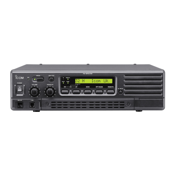
PANEL DESCRIPTION !6 ANI CLEAR SWITCH [ANI CLR] D D Function display Push for 1 sec. to clear the received ANI ID indica- tion on the display and return to the original indica- 32HH@HICOMHINC. tion. NOTE: This switches’ function is not available for some versions. -
Page 6: D Accessory Connector
PANEL DESCRIPTION D Remote connector Pin No. Pin Name Description Specification Input terminals to transmit the repeater in rela- –PTT High voltage=PTT ON (transmits) tion to the external equipment. An opto-isolator Hi-Z=PTT OFF is provided to facilitate PTT signals. +PTT Output terminal for AF signals from the AF de- –AFOUT Output impedance: 600 Ω... - Page 7 PANEL DESCRIPTION Accessory connector (continued) Pin No. Pin Name Description Specification M/S OUT Output terminal for master/slave signal. Open collector=OFF, 0V=ON Input terminal for selecting memory channel. +5 V pull up, Active=L Input terminal for selecting memory channel. +5 V pull up, Active=L Input terminal for selecting memory channel.
-
Page 8: Installation And Connections
For a description and a diagram of accessory equip- ceiving frequencies. Ask your Dealer for details. ment included with the IC-FR3100/FR4100 series, see ‘Supplied Accessories’ on p. ii of this manual. I Grounding... -
Page 9: I Required Connections
CAUTION: DO NOT short pin 1 to ground as this can damage the internal 9 V regulator. DC voltage is applied to pin 1 for microphone operation. Take care when using a non-Icom microphone. [DC POWER INPUT TERMINAL] (p. 8) + red... -
Page 10: I Advanced Connections
INSTALLATION AND CONNECTIONS I Advanced connections LINE CONNECTOR (Front panel view) q NC (No connection) to telephone connector w L1 input/output e L2 input/output r NC (No connection) Telephone connector type is different for some countries. EXTERNAL SPEAKER Use a 4 Ω speaker. BATTERY EXT SP REMOTE... -
Page 11: I Power
(emergency power supply). available for mounting the repeater into a 19 inch rack. The IC-FR3100/FR4100 series can operate with an AC The MB-78 can install the repeater’s bottom side and or DC power supply. If AC power is interrupted when top side. - Page 12 INSTALLATION AND CONNECTIONS • Top side installation q Remove the screws (M4 × 8) from both sides of the t Remove the 2 screws (M4 × 8) from both sides of MB-78. the side panel (front-end). w Remove the handles from the bottom bar. And turn y Attach the MB-78 to the top side of the repeater.
-
Page 13: Connections
INSTALLATION AND CONNECTIONS D Using the optional MB-77 • Mount the MB-77 securely with the 12 supplied An optional MB-77 is available WALL MOUNT BRACKET screws (M6 × 30) to a surface which is more than 50 for mounting the repeater to a flat surface. mm thick and can support more than 20 kg (44 lb). -
Page 14: Optional Unit Installation
OPTIONAL UNIT INSTALLATION I Opening the repeater’s case Follow the case and cover opening procedures shown here when an optional unit is installed or when adjust- ing the internal units, etc. CAUTION: DISCONNECT the AC power cable and/or DC power cable from the repeater. Other- wise, there is danger of electric shock and/or equip- ment damage. -
Page 15: Operation
Push [POWER] to turn the power ON. w If the repeater is programmed for a power on pass- word by an Icom Dealer, input the digit codes di- rectly. • The keys in the table below can be used for password input. -
Page 16: Maintenance
The following chart is designed to help correct prob- If you are unable to locate the cause of a problem or lems which are not equipment malfunctions. solve it through the use of this chart, contact the near- est Icom Dealer or Service Center. PROBLEM POSSIBLE CAUSE SOLUTION REF. -
Page 17: I Fuse Replacement
MAINTENANCE I Fuse replacement R R WARNING: If a fuse blows or the repeater stops functioning, try to DISCONNECT the AC power find the source of the problem, and replace the dam- cable and/or DC power cable from the repeater. aged fuse with a new, rated fuse. -
Page 18: Specifications And Options
SPECIFICATIONS AND OPTIONS I Specifications Specifications are measured in accordance with EN 300 086. D D IC-FR3100 Receiver General • Receive system : Double conversion • Frequency coverage : 150.000–174.000 MHz superheterodyne system • Channel spacing : 12.5/25.0 kHz (Narrow/Wide) •... -
Page 19: I Options
SPECIFICATIONS AND OPTIONS I Options Transmitter • RF output power : 25 W • Modulation system : Variable reactance frequency • MB-77 WALL MOUNT BRACKET (p. 10) modulation system For mounting the repeater to a wall. • Max. frequency deviation : ±5.0 kHz (Wide), ±4.0 kHz (Middle), •... -
Page 20: About Ce
ABOUT CE INSTALLATION NOTES • Compliance of base station transmitter installa- • Installation with a vertical type antenna at tions with EN50385 VHF-UHF The installation of this equipment and it’s associated You need to consider the distances between the an- antenna should be made in such a manner as to re- tenna and any point where persons may have access. - Page 21 1.5 m and a height clearance of 3 m. CE Versions of the IC-FR3100/FR4100 The antenna installation needs to ensure that the low- which display the “CE” symbol on the serial...
-
Page 22: About Ce
ABOUT CE DECLARATION OF CONFORMITY We Icom Inc. Japan 0168 1-1-32, Kamiminami, Hirano-ku Osaka 547-0003, Japan Declare on our sole responsibility that this equipment complies with the essential requirements of the Radio and Telecommunications Terminal Equipment Directive, 1999/5/EC, and that any applicable Essential Test Düsseldorf 23rd May 2003... - Page 23 MEMO...
- Page 24 Count on us! <Intended Country of Use> A-6280H-1EU Printed in Japan 1-1-32 Kamiminami, Hirano-ku, Osaka 547-0003 Japan © 2003 Icom Inc.
- Page 25 ETSI document “A guide to the application of TBR21,” 0168 EG201 121 V1.1.3 (02-2002). This notice applies to all IC-FR3100/IC-FR4100 that are marked This product has been tested in accordance with TBR21 for pan-European single terminal connection to the Public Switched Telephone Network (PSTN).