Table of Contents
Advertisement
Quick Links
Advertisement
Table of Contents

Related Manuals for Advent ADV10A


Summary of Contents for Advent ADV10A
-
Page 1: Installation Guide
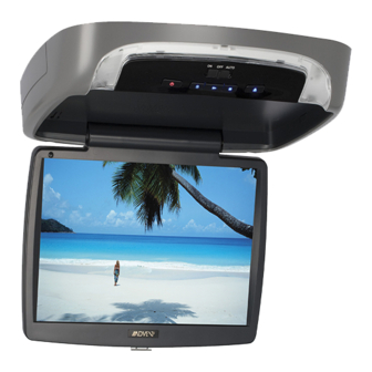
ADV10A " 1 OVERHEAD LCD MONITOR WITH DVD PLAYER Installation Guide... -
Page 2: Important Note
Important Note The ADV10A incorporates two new features: 1) A wireless FM Modulator 2) Snap on Covers with matching Trim Rings (Shale and Pewter). - Page 3 MATERIALS INCLUDED IN THIS PACKAGE: 1) 10.1” TFT LCD Overhead Monitor With DVD Player - (1 pc) 2) Hardware Package (P/N 150-1661) - (1 pc) - M3 x 8mm Phillips Screws (P/N 100-2427) - (5 pcs) - #4 x 5/16" Phillips Self Tapping Screws (P/N 100-2316) - (1 pc) - #4 x 7/16"...
- Page 4 Installing the Snap On Covers Housing Snap On Cover Snap On Cover Pry Tool Screw Cap (Shroud) (Screen Back Cab) (L & R) 1 Pewter, 1 Shale 1 Pewter, 1 Shale 2 Pewter, 2 Shale Place the unit on a soft surface to avoid damaging the plastic. Installing The Shroud catch catch...
- Page 5 Removing the Snap On Cover (Shroud) from the Housing Work on a soft surface to avoid damaging the plastic. Insert the supplied pry tool between the Housing and Snap On Cover (Shroud), then press the pry tool to release the Snap On Cover (Shroud).
-
Page 6: Vehicle Preparation
2) The mounting method and location will vary from vehicle to vehicle, so this manual will only focus on the installation of the ADV10A and related console accessories. 3) Generally, the best location for the video monitor is where the vehicle's factory dome light is installed. -
Page 7: General System Configurations
ADV10A Drop Down Video Systems: The ADV10A has an option that allows the user to select from two IR transmit and receive codes (M1 or M2). This feature can be used when using two ADV10As in the same installation or if the vehicle has an RSA (Rear Seat Audio) that uses an “A”... -
Page 8: Trim Ring Installation
TRIM RING INSTALLATION: Note: This page only covers special installation considerations for thick trim ring installation. If the video monitor is to be installed in a vehicle with the thick trim ring, it may need to be trimmed to fit the contour of the vehicle Headliner. - Page 9 TRIM RING INSTALLATION: To install the Trim Ring to the unit, use the supplied screws listed below: #4 x 5/16 Phillips Self Tapping Screws (1 pc) #4 x 7/16 Phillips Self Tapping Screws (3 pcs) M3 x 8mm Phillips Screws (5 pcs) Please see the illustration below for screw locations.
-
Page 10: Wiring Diagram
WIRING DIAGRAM 2 Pin Power Harness (P/N 112-4152) Dome Light Extension Harness (P/N 112-3884) * Antenna for Wireless FM Mod. ** See Antenna Note 1) Make the connections to the vehicle for the 10 pin wiring harness. 2) Connect 2 Pin Power Harness to vehicle’s electrical system by tapping into an accessory hot line and a good ground. -
Page 11: Connecting The Dome Lights
CONNECTING THE DOME LIGHTS The dome lights in the video monitor require three connections to the vehicle's wiring. There are two common types of dome light circuits used, positive switched systems or negative switched systems. Positive switched systems supply voltage to the interior lights to turn on; negative switched systems apply ground to illuminate the bulbs. -
Page 12: Troubleshooting
Verify that the correct source is selected (i.e.: 1, 2, 3 or 4). Verify that the source is on and playing a known good media (such as a videotape). Verify the connections at both ends of the source component harness. © 2011 ADVENT, 150 Marcus Blvd. Hauppauge, NY 11788 128-8934...