Table of Contents
Advertisement
Instruction
manual
To learn more about Porter-Cable
visit our website at:
http://www.porter-cable.com
Copyright © 2004 Porter-Cable Corporation
ESPAÑOL: PÁGINA 27
FRANÇAIS: PAGE 53
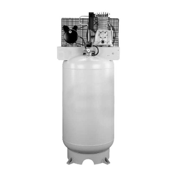
Oil Lube Two Stage
Air Compressor
Please make certain that the person who is
to use this equipment carefully reads and
understands these instructions before
starting operations.
The Model and Serial No. plate is located on the frame.
Record these numbers in the spaces below and retain for
future reference.
®
Model No.
Type
Serial No.
CPLKC7080V2
IMPORTANT
Part No. D22944-049-2
Advertisement
Table of Contents

Related Manuals for Porter-Cable CPLKC7080V2


Summary of Contents for Porter-Cable CPLKC7080V2
-
Page 1: Instruction Manual
FRANÇAIS: PAGE 53 Oil Lube Two Stage Air Compressor CPLKC7080V2 IMPORTANT Please make certain that the person who is To learn more about Porter-Cable visit our website at: to use this equipment carefully reads and understands these instructions before http://www.porter-cable.com starting operations. -
Page 2: Safety Guidelines - Definitions
This tool was designed for certain applications. Porter-Cable strongly recommends that this tool NOT be modified and/or used for any application other than for which it was designed. If you have any questions relative to its application DO NOT use the tool until you have written Porter-Cable and we have advised you. -
Page 3: Risk Of Explosion Or Fire
IMPORTANT SAFETY INSTRUCTIONS SAVE THESE INSTRUCTIONS IMPROPER OPERATION OR MAINTENANCE OF THIS PRODUCT COULD RESULT IN SERIOUS INJURY AND PROPERTY DAMAGE. READ AND UNDERSTAND ALL WARN- INGS AND OPERATING INSTRUCTIONS BEFORE USING THIS EQUIPMENT. HAZARD RISK OF EXPLOSION OR FIRE WHAT CAN HAPPEN HOW TO PREVENT IT ALWAYS OPERATE THE COMPRESSOR IN A... -
Page 4: Risk Of Bursting
HAZARD RISK OF BURSTING AIR TANK: THE FOLLOWING CONDITIONS COULD LEAD TO A WEAKENING OF THE TANK, AND RESULT IN A VIOLENT TANK EXPLOSION AND COULD CAUSE PROP- ERTY DAMAGE OR SERIOUS INJURY. WHAT CAN HAPPEN HOW TO PREVENT IT FAILURE TO PROPERLY DRAIN CON- DRAIN TANK DAILY OR AFTER EACH USE. -
Page 5: Risk Of Electrical Shock
HAZARD RISK OF ELECTRICAL SHOCK WHAT CAN HAPPEN HOW TO PREVENT IT NEVER OPERATE THE COMPRESSOR OUT- YOUR AIR COMPRESSOR IS POWERED BY DOORS WHEN IT IS RAINING OR IN WET CON- ELECTRICITY. LIKE ANY OTHER ELECTRI- DITIONS. CALLY POWERED DEVICE, IF IT IS NOT USED PROPERLY IT MAY CAUSE ELECTRIC NEVER OPERATE COMPRESSOR WITH PRO- SHOCK. -
Page 6: Risk From Moving Parts
HAZARD RISK OF BURNS WHAT CAN HAPPEN HOW TO PREVENT IT TOUCHING EXPOSED METAL SUCH AS THE NEVER TOUCH ANY EXPOSED METAL COMPRESSOR HEAD OR OUTLET TUBES, PARTS ON COMPRESSOR DURING OR IMME- DIATELY AFTER OPERATION. COMPRESSOR CAN RESULT IN SERIOUS BURNS. WILL REMAIN HOT FOR SEVERAL MINUTES AFTER OPERATION. - Page 7 HAZARD RISK OF UNSAFE OPERATION WHAT CAN HAPPEN HOW TO PREVENT IT UNSAFE OPERATION OF YOUR AIR COM- REVIEW AND UNDERSTAND ALL INSTRUC- PRESSOR COULD LEAD TO SERIOUS INJURY TIONS AND WARNINGS IN THIS MANUAL. OR DEATH TO YOU OR OTHERS. BECOME FAMILIAR WITH THE OPERATION AND CONTROLS OF THE AIR COMPRESSOR.
-
Page 8: Duty Cycle
Maximum This means an air compressor that compressor pumping time per hour is pumps air more than 50% of one 30 minutes. SPECIFICATIONS Model No. CPLKC7080V2 Horsepower Peak Voltage-Single Phase 240V/60Hz/1Ph Minimum Branch Circuit Requirement 30 amps *Fuse Type... -
Page 9: Tools Required For Assembly
ASSEMBLY Tools Required for Assembly Obtain the drain plug extension (D), from the parts bag. 1 - 9/16" socket or open end wrench 1 - electric drill Unpacking Remove all packaging. It may be neces- sary to brace or support one side of the outfit when removing the pallet because the air compressor will have a tendency to tip. -
Page 10: Location Of The Air Compressor
INSTALLATION HOW TO SET UP YOUR UNIT Place the air compressor on on a solid, level surface. Location of the Air Compressor Mark the surface using the holes • Locate the air compressor in a in the air compressor feet as a clean, dry, and well ventilated template. -
Page 11: Wiring Instructions
Wiring Instructions GROUNDING INSTRUCTIONS RISK OF ELECTRI- This product should be connected to CAL SHOCK. a metallic, permanent wiring system, Improper electrical grounding can or an equipment-grounding terminal result in electrical shock. The or lead on the product and comply wiring should be done by a quali- with national and local electrical fied electrician to comply with... - Page 12 • Use pipe that is the same size as • Install a flexible coupling the air tank outlet. Piping that is between the air discharge outlet too small will restrict the flow of and main air distribution line to air. allow for vibration.
-
Page 13: Know Your Air Compressor
OPERATION Know Your Air Compressor READ THIS OWNER’S MANUAL AND SAFETY RULES BEFORE OPERATING YOUR UNIT. Compare the illustrations with your unit to familiarize yourself with the location of various controls and adjustments. Save this manual for future reference. Description of Operation Become familiar with these controls before operating the unit. -
Page 14: Before Starting Break-In Procedure
Air Compressor Pump (not shown): Compresses Check Valve air into the air tank. Working air is not available until the compressor has raised the air tank pressure above that required at the air outlet. Check Valve: When the air compressor is operating, the check valve is "open", allowing compressed air to enter the air tank. -
Page 15: Before Each Start-Up
Check all air line fittings and connections/piping for air leaks by applying a soap solution. Correct if necessary. NOTE: Minor leaks can cause the air compressor to overwork, resulting in premature breakdown or inadequate performance. Check for excessive vibration. Readjust or shim air compressor feet, if necessary. -
Page 16: Maintenance
MAINTENANCE Customer Responsibilities Before Every Every Every Every Every each Yearly hours hours hours hours hours ● Check Safety Valve ● Drain Tank ● Check Oil ● ● Change Oil Unusual Noise and/or ● Vibration ● Air Filter Drive Belt-Condition ●... -
Page 17: To Drain Tank
To Drain Tank NOTE: Operation of the air compres- sor will cause condensation to build up in the air tank. Always drain tank on a washable surface or in a suit- able container to prevent damaging or staining surfaces. Set the On/Auto/Off lever to "OFF". -
Page 18: Adjusting Belt Tension
See the "Adjust Belt Tension" Air Filter - Inspection and before tightening motor mount- Replacement ing screws. Hot surfaces. Risk of burn. Adjusting Belt Tension Compressor heads are exposed Slide motor into original position, when filter cover is removed. line the motor up with the mark Allow compressor to cool prior to made earlier on saddle. -
Page 19: Air Compressor Pump Intake And Exhaust Valves
Visually inspect the motor drive Motor Pulley/Flywheel pulley to verify that it is perpen- Alignment dicular to the drive motor shaft. NOTE: Once the motor pulley has Points B1 and B2 of Figure been moved from its factory set loca- should appear to be equal. -
Page 20: Service And Adjustments
SERVICE AND ADJUSTMENTS Unscrew the check valve (turn Unit cycles automat- counterclockwise) using a 7/8" ically when power is open end wrench. Note the on. When doing Maintenance, you orientation for reassembly. may be exposed to voltage sources, compressed air or moving Using a screwdriver, carefully parts. -
Page 21: Additional Service
Place the On/Auto/Off lever in Motor the On/Auto postion to restart This motor has a manual thermal the motor. overload protector. If the motor over- IMPORTANT: If the overload protec- heats for any reason, the overload tor shuts the motor off frequently, protector will shut off the motor. -
Page 22: Troubleshooting
TROUBLESHOOTING Performing repairs may expose voltage sources, moving parts or compressed air sources, moving parts or compressd air sources. Personal injury may occur. Prior to attempting any repairs, unplug the air compressor and bleed off all air tank air pressure. CORRECTION PROBLEM CAUSE... - Page 23 PROBLEM CORRECTION CAUSE If there is an excessive amount It is normal for "some" Pressure reading of pressure drop when the pressure drop to occur. on the regulated accessory is used, adjust the pressure gauge regulator as instructed in the (if equipped) Operation section.
- Page 24 PROBLEM CORRECTION CAUSE Motor will not Let motor cool off and over- Motor overload protection load switch will automatically run. switch has tripped. reset. Motor will start automatically Tank pressure exceeds when tank pressure drops pressure switch "cut-in" below "cut-in" pressure of pressure.
- Page 25 CORRECTION CAUSE PROBLEM Knocking Noise. Possible defect in safety Operate safety valve manually valve. by pulling on ring. If valve still leaks, it should be replaced. Defective check valve. Remove and clean, or replace. Loose pulley. Tighten pulley set screw, 145-165 in.-lbs.
-
Page 26: Limited Warranty
90 Day – Service parts Engine warranties are the responsibility of the engine manufacturer. Warranties of mer- chandise sold by Porter-Cable which has been manufactured by and identified as the product of another company are the responsibility of the manufacturer of that product.