Table of Contents
Advertisement
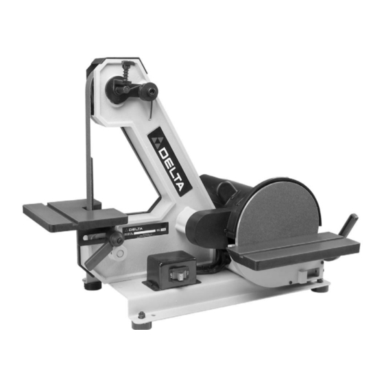
1" Belt / 8" Disc Sander
(Model 31-340)
PART NO. 902120 (0112)
Copyright © 2001 Delta Machinery
To learn more about DELTA MACHINERY
ESPAÑOL: PÁGINA 19
visit our website at: www.deltamachinery.com.
For Parts, Service, Warranty or other Assistance,
1-800-223-7278 (
1-800-463-3582).
please call
In Canada call
Advertisement
Table of Contents

Related Manuals for Delta 31-340


Summary of Contents for Delta 31-340
- Page 1 1" Belt / 8" Disc Sander (Model 31-340) PART NO. 902120 (0112) Copyright © 2001 Delta Machinery To learn more about DELTA MACHINERY ESPAÑOL: PÁGINA 19 visit our website at: www.deltamachinery.com. For Parts, Service, Warranty or other Assistance, 1-800-223-7278 ( 1-800-463-3582).
-
Page 2: General Safety Rules
If you have any questions relative to a particular application, DO NOT use the machine until you have first contacted Delta to determine if it can or should be performed on the product. -
Page 3: Additional Safety Rules For Belt / Disc Sanders
27. THE USE of attachments and accessories not recom- 10. SUPPORT workpiece firmly with the miter gage, back- mended by Delta may result in the risk of injuries. stop or work table when sanding with the belt. NOTE: The SHOULD any part of your sander be missing, dam-... -
Page 4: Power Connections
POWER CONNECTIONS A separate electrical circuit should be used for your machines. This circuit should not be less than #12 wire and should be protected with a 20 Amp time lag fuse. If an extension cord is used, use only 3-wire extension cords which have 3- prong grounding type plugs and matching receptacle which will accept the machine’s plug. -
Page 5: Extension Cords
OPERATING INSTRUCTIONS FOREWORD Delta Model 31-340 is the ultimate workshop machine for wood sanding and metal grinding. The 3000 SFM belt speed is ideal for metal grinding, deburring and sharpening, as well as sanding and buffing jobs. The 8" diameter disc operates at 1725 rpm for finishing hard and soft woods, plastics, compositions and more. -
Page 6: Belt Tension
ASSEMBLY WARNING: FOR YOUR OWN SAFETY, DO NOT CONNECT THE MACHINE TO THE POWER SOURCE UNTIL THE MACHINE IS COMPLETELY ASSEMBLED AND YOU READ AND UNDERSTAND THE ENTIRE INSTRUCTION MANUAL. ASSEMBLING BELT UNIT TO BASE 1. Place a 10mm lockwasher (D) Fig. 1, and a 10mm flat washer (E) onto a M10x20mm hex socket head screw (A) and insert the screw up through the hole (B) in the base. -
Page 7: Assembling Sanding Disc To Disc Plate
ASSEMBLING GUARD FOR SANDING DISC AND BELT AND PULLEYS 1. DISCONNECT MACHINE FROM POWER SOURCE 2. Position the guard (A) Fig. 5, in place on the disc unit frame and fasten in place using the two M4X10mm cheese head screws (B) and (C) and two 3/16" flat washers. - Page 8 ASSEMBLING SANDING DISC PLATE TO MOTOR SHAFT 1. DISCONNECT MACHINE FROM POWER SOURCE. 2. Assemble the sanding disc plate (A) Fig. 9, to the motor shaft with the key (B) in the motor shaft, engaged with the keyway (C) in the hub of the sanding disc. 3.
- Page 9 ASSEMBLING SANDING DISC TABLE 1. DISCONNECT MACHINE FROM POWER SOURCE. 2. Two clamp handles are supplied with your machine, one for the belt sander table and one for the disc sander table. Disassemble both handles by unscrewing and re- moving screw (A), spring (B), and handle (C) from locking stud (D), as shown in Fig.
-
Page 10: Assembling Belt Sander Table
ASSEMBLING BELT SANDER TABLE 1. DISCONNECT MACHINE FROM POWER SOURCE. 2. Position the table assembly (A) Fig. 17, in position on the belt sander frame and using locking stud (B), from handle assembly, and flat washer (C), thread locking stud (B) into threaded hole in casting to hold table assembly in place, as shown. -
Page 11: Sanding Belt
TRACKING THE SANDING BELT The belt tracking adjustment is set at the factory so that the belt (A) Fig. 23, will run true on the pulleys. If, however, the belt (A) should lead to one side or the other on the pulleys, an adjustment can be made by turning the tracking knob (B). -
Page 12: Disc Table Adjustments
The table can be tilted 45 degrees to the front, as shown in Fig. 27, by loosening lock lever (B). Using a combination square (E) check to see if the table is at 45 degrees to the belt and tighten lock lever (B). WARNING: TO AVOID TRAPPING THE WORK OR FINGERS BETWEEN THE TABLE AND SANDING BELT,... -
Page 13: Dust Chutes
REMOVING AND INSTALLING ABRASIVE BELTS 1. DISCONNECT MACHINE FROM POWER SOURCE. 2. Unscrew and remove the two knobs (A) Fig. 31, and remove the side cover (B) from the belt unit. 3. Press down on the tracking knob to release belt tension and remove belt (C) Fig. -
Page 14: Typical Operations
ACCESSORIES NOT RECOMMENDED BY DELTA MAY RESULT IN RISK OF INJURIES. The following are just some of the many operations that can be performed with your Delta 1" Belt/8" Disc Sander. Sharpening a cold chisel on the belt unit with the table tilted. - Page 15 Polishing using the Delta accessory Felt Belt in place of the sanding belt. Fig. 39 Sanding in tight areas with the sanding belt. Fig. 40 Inside curves can be sanded on the top sanding wheel with the side cover removed.
-
Page 16: Parts, Service Or Warranty Assistance
Two Year Limited Warranty Delta will repair or replace, at its expense and at its option, any Delta machine, machine part, or machine accessory which in normal use has proven to be defective in workmanship or material, provided that the customer returns the product prepaid to a Delta factory service center or authorized service station with proof of purchase of the product within two years and provides Delta with reasonable opportunity to verify the alleged defect by inspection. - Page 17 NOTES...
- Page 18 NOTES...