Table of Contents
Advertisement
Sanding Center
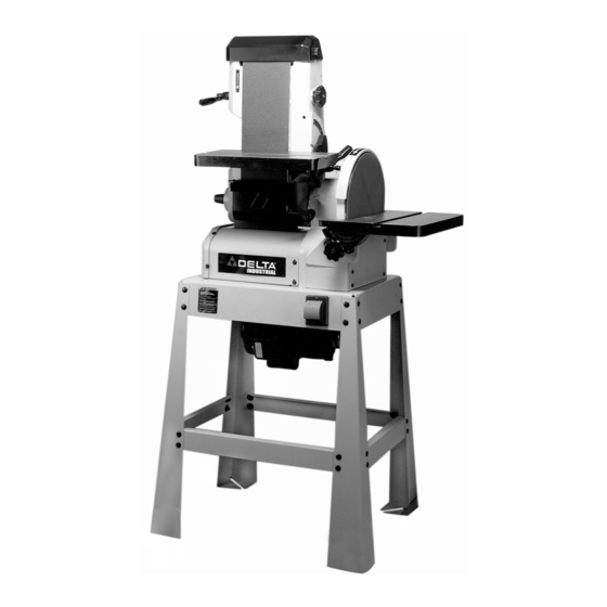
6" Belt/12" Disc Sander
(Model 31-300)
PART NO. 913131
-
04-12-05
Copyright © 2005 Delta Machinery
To learn more about DELTA MACHINERY
visit our website at: www.deltamachinery.com.
For Parts, Service, Warranty or other Assistance,
1-800-223-7278 (
1-800-463-3582).
please call
In Canada call
Advertisement
Table of Contents

Related Manuals for Delta (Model 31-300)


Summary of Contents for Delta (Model 31-300)
- Page 1 Sanding Center 6" Belt/12" Disc Sander (Model 31-300) PART NO. 913131 04-12-05 Copyright © 2005 Delta Machinery To learn more about DELTA MACHINERY visit our website at: www.deltamachinery.com. For Parts, Service, Warranty or other Assistance, 1-800-223-7278 ( 1-800-463-3582). please call...
-
Page 2: Table Of Contents
NOT be modified and/or used for any application other than for which it was designed. If you have any questions relative to its application DO NOT use the product until you have written Delta Machinery and we have advised you. -
Page 3: Safety Guidelines
SAFETY GUIDELINES - DEFINITIONS It is important for you to read and understand this manual. The information it contains relates to protecting YOUR SAFETY and PREVENTING PROBLEMS. The symbols below are used to help you recognize this information. Indicates an imminently hazardous situation which, if not avoided, will result in death or serious injury. Indicates a potentially hazardous situation which, if not avoided, could result in death or serious injury. -
Page 4: General Safety Rules
GENERAL SAFETY RULES IMPORTANT SAFETY INSTRUCTIONS Delta may cause damage to the machine or injury to the user. 14. USE THE PROPER EXTENSION CORD. Make sure your extension cord is in good condition. When using an extension cord, be sure to use one heavy enough to PROTECTION. -
Page 5: Additional Specific Safety Rules
ADDITIONAL SPECIFIC SAFETY RULES FAILURE TO FOLLOW THESE RULES MAY RESULT IN SERIOUS PERSONAL INJURY. 1. DO NOT OPERATE THIS MACHINE until it is completely assembled and installed according to the instructions. A machine incorrectly assembled can cause serious injury. 2. -
Page 6: Power Connections
POWER CONNECTIONS A separate electrical circuit should be used for your machines. This circuit should not be less than #12 wire and should be protected with a 20 Amp time lag fuse. If an extension cord is used, use only 3-wire extension cords which have 3- prong grounding type plugs and matching receptacle which will accept the machine’s plug. -
Page 7: Extension Cords
UL/CSA listed plug suitable for 240 volts and the rated current of your machine as illustrated in Fig. C. Contact your local Authorized Delta Service Center or qualified electrician for proper procedures to install the plug. The machine must comply with all local and national electrical codes after the 240 volt plug is installed. -
Page 8: Functional Description
FOREWORD Delta Model 31-300 is an industrial/commercial duty 1-1/2 HP belt/disc sander. The induction-type, ball-bearing motor provides long-lasting, smooth performance. The Sanding Center can provide 3000 SFPM with the belt, and the disc will revolve at 2100 RPM. NOTICE: THE PHOTO ON THE MANUAL COVER ILLUSTRATES THE CURRENT PRODUCTION MODEL. -
Page 9: Assembly
For assembling stand: -18 x " Carriage Bolt (32) " Lock Washer (32) " Flat Washer (32) "-18 Hex nut (32) To attach center to stand " Hex Head Bolt (4) " Lock Washer (4) 27. #10-32 x " Machine screws (4) 28. - Page 10 INSTALLING DRIVE BELT AND BELT GUARD DISCONNECT MACHINE FROM POWER SOURCE. NOTE: MAKE SURE THE BELT IS ON THE SANDER DRIVE PULLEY. Slip belt (A) Fig. 8A, over motor pulley (B). Allow motor to drop and pull belt tight. Be sure the pulleys are aligned properly. To adjust, loosen set screw (E) Fig.
-
Page 11: Attaching Sanding Disc
ATTACHING SANDING DISC DISCONNECT MACHINE FROM POWER SOURCE. Clean the sanding disc plate (A) Fig. 9 of any oil or grease, and be certain that it is dry. Peel approximately 1/2 of the backing (B) Fig. 9 from the sanding disc (C). Insert the sanding disc (C) Fig. -
Page 12: Operation
STARTING AND STOPPING THE MACHINE The on-off switch (A) Fig. 16 is located on the sander base. To turn the sander “ON”, move the switch to the up position. To turn the sander “OFF”, move the switch to the down position. -
Page 13: Overload Protection
OVERLOAD PROTECTION The motor supplied with your sander is equipped with a reset overload relay button (A) Fig. 18. If the motor shuts off or fails to start because of overloading (sanding too heavy, using a worn sanding belt or disc, using the sander beyond its capacity), or low voltage, turn the switch (A) Fig. - Page 14 Adjust the pointer, if necessary. TILTING THE BELT SANDER TABLE DISCONNECT MACHINE FROM POWER SOURCE. The table (A) can be tilted 45 degrees down (Fig. 25). To tilt the table, loosen the lock handle (B), tilt the table to the desired angle, and tighten the lock handle (B).
- Page 15 ADJUSTING BELT SANDER TABLE MITER GAUGE SLOT PARALLEL TO SANDING BELT DISCONNECT MACHINE FROM POWER SOURCE 1. Position the table (A) (Figs. 27 and 28) 90 degrees to the belt. Place a square (B) in the miter gauge slot with the blade (C) of the square touching the sanding belt.
- Page 16 4. The stop (F) Fig. 32 ensures that the table can rapidly return 90 degrees to the disc after the table has been tilted. 5. Adjust pointer, if necessary. TILTING THE DISC SANDER TABLE DISCONNECT MACHINE SOURCE.
- Page 17 5. Apply tension to the sanding belt and replace the top cover removed in STEP 2. 6. Tighten the two screws loosened in STEP 3. 7. Connect the power source to the sander and check for proper belt tracking. Fig. 38 REPLACING SANDING DISC DISCONNECT MACHINE FROM POWER SOURCE.
- Page 18 MACHINE USE Fig. 44 SURFACING OR EDGE SANDING WITH SANDING BELT When surfacing (Fig. 44) or edge sanding (Fig. 45), place the sanding arm in the horizontal position and use the table (A) Fig. 44 and Fig. 45 to keep the workpiece in place. Hold the workpiece firmly and keep your fingers away from the sanding belt.
- Page 19 Fig. 48 END SANDING WITH THE DISC When sanding the ends of narrow workpieces, use the sanding disc and an accessory miter gauge (A) Fig. 48. Move the work from the center to the left side (downward) of the sanding disc. ALWAYS SAND ON THE LEFT SIDE (DOWNWARD ROTATION SIDE) OF THE SANDING DISC.
-
Page 20: Troubleshooting
Also, check for blown fuses or open circuit breakers in the line. PARTS, SERVICE OR WARRANTY ASSISTANCE All Delta Machines and accessories are manufactured to high quality standards and are serviced by a network • of Porter-Cable Delta Factory Service Centers and Delta Authorized Service Stations. To obtain additional information regarding your Delta quality product or to obtain parts, service, warranty assistance, or the location of the nearest service outlet, please call 1-800-223-7278 (In Canada call 1-800-463-3582). -
Page 21: Accessories
Two Year Limited New Product Warranty Delta will repair or replace, at its expense and at its option, any new Delta machine, machine part, or machine accessory which in normal use has proven to be defective in workmanship or material, provided that the customer returns the product prepaid to a Delta factory service center or authorized service station with proof of purchase of the product within two years and provides Delta with reasonable opportunity to verify the alleged defect by inspection. - Page 22 NOTES...
- Page 23 NOTES...
- Page 24 Phone: (604) 420-0102 Fax: (604) 420-3522 The following are trademarks of PORTER-CABLE • DELTA (Las siguientes son marcas registradas de PORTER-CABLE • DELTA S.A.) (Les marques suivantes sont des marques de fabriquant de la PORTER-CABLE • DELTA): Auto-Set Contractor’s Saw II™, Delta ®...