Table of Contents
Advertisement
Advertisement
Table of Contents

Related Manuals for Asus A8AE-LE Amberine


Summary of Contents for Asus A8AE-LE Amberine
- Page 1 A8AE-LE (Amberine/ AmberineM) User Guide...
-
Page 2: Table Of Contents
Contents A8AE-LE (Amberine/AmberineM) specifications summary .... iii Motherboard layout ............... 1 Central Processing Unit (CPU) ..........2 2.1 Overview ................. 2 2.2 Installing the CPU ............2 System memory ..............3 3.1 Installing a DIMM ............. 3 Expansion slots ..............4 4.1 Standard interrupt assignments ........ -
Page 3: A8Ae-Le(Amberine/Amberinem) Specifications Summary
Dual Channel memory Supports PC3200/2700 DDR 1 x PCI-Express x16 slot Expansion slots 3 x PCI slots 1 x ASUS proprietary PCI expander connector (AmberineM no Support) Storage ATI SB400 Supports : 2 x UltraDMA100/66/33 connectors, PIO Mode 3/4 Supports 4 ATAPI IDE, CD-ROM, CD-R, CD-RW and LS-120... - Page 4 Internal I/O 1 x Floppy connector 2 x USB 2.0 connectors for additional 4 USB ports 1 x IEEE 1394 connector for additional 1394 port 1 x CPU and SYSTEM/Chassis FAN connector 1 x 24-pin ATX power connector 1 x 4-pin ATX power connector 1 x Serial port 1 x S/PDIF out connector 1 x CD/AUX audio connectors...
-
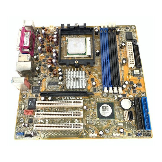
Page 5: Motherboard Layout
B: USB4 Flash SPDIFOUT1 RS482 Top:Line In Center:Line Out Below:Mic In RTL8101L PCIEX1 A8AE-LE CR2032 3V VT6307 PCI1 Lithium Cell CMOS Power SB400 F_1394 PCI2 ALC658 SATA2 SATA1 AUX_IN1 F_AUDIO1 PCI45 CLRTC CLPWD CD_IN1 F_USB1 F_USB2 F_PANEL1 ASUS A8AE-LE (Amberine/AmberineM) Motherboard... -
Page 6: Central Processing Unit (Cpu)
Take note of the marked corner (with gold triangle) on the CPU. This mark should match a specific corner on the socket to ensure correct installation. A8AE-LE A8AE-LE CPU Socket 939 Installing the CPU Follow these steps to install a CPU. -
Page 7: System Memory
The following figure illustrates the location of the DDR DIMM sockets. A8AE-LE A8AE-LE 184-pin DDR DIMM sockets CAUTION: DIMMs are keyed to fit with only one direction. DO NOT force a DIMM into a socket to avoid damaging the DIMM. -
Page 8: Expansion Slots
PCI slot 4 INTD# INTA# INTB# INTC# PCI slot 5 INTA# INTB# INTC# INTD# Onboard 1394 controller INTE# *Onboard USB controller 1 INTD# *Onboard LAN INTF# *The onboard USB, LAN and audio IRQs are assigned by the BIOS. ASUS A8AE-LE (Amberine/AmberineM) Motherboard... -
Page 9: Pci Slots
PCI Express x1 slot This motherboard supports PCI Express x1 network card, SCSI cards and other cards that comply with the PCI Express specifications. The figure shows a network card install on the PCI Express x1 slot. ASUS A8AE-LE (Amberine/AmberineM) Motherboard... -
Page 10: Jumpers
CLRTC A8AE-LE Clear CMOS Normal A8AE-LE Clear RTC RAM (Default) 2. Clear Password (3-pin CLPWD) This jumper allows you to clear the password in CMOS. To erase the Password move the jumper cap from pins 2-3 (Default) to pins 1-2 (Clear Password). Keep the cap on pins 1-2 for about 5~10 seconds, then move the cap back to pins 2-3. -
Page 11: Connectors
6 - c h a n n e l 6 - c h a n n e l Light Blue Line In Line In Line In Lime Line Out Front Speaker Out Front Speaker Out Pink Mic In Mic In Center/Subwoofer ASUS A8AE-LE (Amberine/AmberineM) Motherboard... - Page 12 12. S-Video Out port. This port connects an external Video output device via a S-Video cable. 13. Composite Out port . This port connects an external audio output device via a Composite cable. 14. PS/2 keyboard port (purple). This port is for a PS/2 keyboard. ASUS A8AE-LE (Amberine/AmberineM) Motherboard...
-
Page 13: Internal Connectors
PIN 1. A8AE-LE PIN 1 A8AE-LE Floppy disk drive connector 2. ATX power connectors (24-pin ATXPWR1, 4-pin ATX12V1) These connectors connect to an ATX 12V power supply. The plugs from the power supply are designed to fit these connectors in only one orientation. Find the proper orientation and push down firmly until the connectors completely fit. - Page 14 2. The hole near the blue connector on the UltraDMA100/66/33 cable is intentional. NOTE: Orient the red markings (usually zigzag) on the IDE ribbon cable to PIN 1. A8AE-LE PIN 1 PIN 1 A8AE-LE IDE connectors ASUS A8AE-LE (Amberine/AmberineM) Motherboard...
- Page 15 A8AE-LE Fan connectors 6. Internal audio connectors (4-pin CD_IN1, AUX_IN1) These connectors allow you to receive stereo audio input from sound sources such as a CD-ROM, TV tuner, or MPEG card. A8AE-LE AUX_IN1 CD_IN1 A8AE-LE Internal audio connectors ASUS A8AE-LE (Amberine/AmberineM) Motherboard...
- Page 16 F_USB1 F_USB2 A8AE-LE A8AE-LE USB 2.0 connectors 8. IEEE 1394 connector (10-1 pin F_1394) This connector is for a 10-to-6-pin 1394 serial connector cable that connects to a 1394 module. Attach the 10-1 pin cable plug to this connector, and the 6-pin cable plug to the 1394 module.
- Page 17 By default, the pins labeled LINE_OUT_R/BLINE_OUT_R and the pins LINE_OUT_L/BLINE_OUT_L are shorted with jumper caps. Remove the caps only when you are connecting the front panel audio cable. F_AUDIO1 A8AE-LE A8AE-LE Front audio connector ASUS A8AE-LE (Amberine/AmberineM) Motherboard...
- Page 18 PWR LED PWR BTN F_PANEL1 A8AE-LE HD LED RESET A8AE-LE System panel connector • System Power LED Lead (2-pin PWR LED) This 3-1 pin connector connects to the system power LED. The LED lights up when you turn on the system power, and blinks when the system is in sleep mode.