Table of Contents
Advertisement
Operating Instructions and Parts Manual
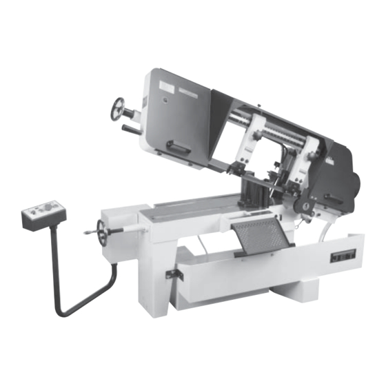
10-Inch x 16-Inch Horizontal Band Saw
Models: J-7020, J-7040
WHM TOOL
GROUP, Inc.
427 New Sanford Road
LaVergne, Tennessee 30786
Ph.: 800-274-6848
www.wmhtoolgroup.com
Model J-7020 shown
Part No. M-414472
Revision A2 04/09
Copyright © 2009 WMH Tool Group, Inc.
Advertisement
Table of Contents

Related Manuals for Jet J-7040


Summary of Contents for Jet J-7040
- Page 1 Operating Instructions and Parts Manual 10-Inch x 16-Inch Horizontal Band Saw Models: J-7020, J-7040 Model J-7020 shown WHM TOOL GROUP, Inc. 427 New Sanford Road LaVergne, Tennessee 30786 Part No. M-414472 Ph.: 800-274-6848 Revision A2 04/09 www.wmhtoolgroup.com Copyright © 2009 WMH Tool Group, Inc.
-
Page 2: Warranty And Service
Service Centers located throughout the United States can give you quick service. In most cases, any of these WMH Tool Group Authorized Service Centers can authorize warranty repair, assist you in obtaining parts, or perform routine maintenance and major repair on your JET® tools. For the name of an Authorized Service Center in your area call 1-800-274-6848. MORE INFORMATION WMH Tool Group is consistently adding new products to the line. -
Page 3: Table Of Contents
Table of Contents General Specifications ............................4 Specifications ..............................4 Machinery General Safety Warnings ........................5 Operating Precautions ............................5 Safety Instructions on Sawing Systems ......................6 General Electrical Cautions ..........................6 Introduction ..............................7 Operating Instructions ............................. 7 Controls ................................7 Setting Blade Speed ............................ -
Page 4: General Specifications
Speeds 100 to 350 feet per minute - variable speed Motor Model J-7020 1.5 H.P., 1 phase, 110/220V Model J-7040 - 2 H.P., 3 phase, 220/440V Blade Size 1" x .035" x 135" Blade Guides Adjustable 6 point contact combination bearing and carbide Blade Wheels 14"... -
Page 5: Machinery General Safety Warnings
Used properly, - Always be sure the machine support is se- JET ’s machinery is among the best in design and curely anchored to the floor or the work bench. safety. However, any machine used improperly can When Using Machine: be rendered inefficient and unsafe. -
Page 6: Safety Instructions On Sawing Systems
General Electrical Cautions Wire Sizes Caution: For circuits which are far away from the electrical service box, the wire size must be increased This saw should be grounded in accordance with in order to deliver ample voltage to the motor. To mini- the National Electrical Code and local codes and mize power losses and to prevent motor overheating ordinances. -
Page 7: Introduction
This manual includes the operating and maintenance 1. The blade speed is controlled by an adjustment instructions for the JET 10-inch by 16-inch Cut Off Band mechanism on the right end of the saw. Speed Saw, Models J-7020/J-7040. This manual also includes increases when the adjustment knob is turned parts listings and illustrations of replaceable parts. -
Page 8: Raising/Lowering The Saw Head
(See Evaluating Blade common materials. A 4/6 vari tooth bi-metal blade Efficiency for more information on cutting efficiency.) (5674011) and a 6/10 vari tooth bi-metal blade (5674021) are available from JET . Blade Tensioning Control Box Blade Guide... -
Page 9: Blade Break-In Procedures
However, the following proce- Clamping Hand dure will be adequate for break-in of JET -supplied blades Wheel Saw Head on lower alloy ferrous materials. Left Vise Jaw 1. -
Page 10: Installation And Adjustment Of Work Stop
place it against the work piece. Angle Set Workpiece Setting Against Corner Starting the Saw of Right Block Vise Jaw Left Vise WARNING: NEVER OPERATE THE SAW WITHOUT BLADE COVERS IN PLACE AND SECURED. Pivot Screw Angle Locking Screw CAUTION: MAKE SURE THE BLADE IS NOT IN CON- TACT WITH THE WORKPIECE WHEN THE MOTOR Figure 6: Adjusting vise IS STARTED. -
Page 11: Coolant Flow
Coolant Flow Blade Tracking Hex Adjustment CAUTION: THE COOLANT PUMP MUST BE SUB- Screws MERGED BEFORE OPERATING TO PREVENT DAM- AGE TO THE PUMP. Single Adjustment Screw 1. The blade guides are fitted with coolant fittings. Coolant is provided to the fittings through intercon- necting tubing. -
Page 12: Blade Guide Bearing Adjustment
the wheel shoulder. Put a 6-inch length of paper should rarely require adjustment. When adjustment is between the blade and the wheel as shown in figure required, adjust immediately. Failure to maintain proper 11. The paper should not be cut as it passes be- blade adjustment may cause serious blade damage or tween the wheel shoulder and the blade. -
Page 13: Test Cutting To Verify Adjustment Accuracy
the center locking screw with an Allen wrench (see tion of the disk you have cut from the bar stock. Mea- figure 12). sure at the top and bottom of the disk. The saw blade can be considered correctly adjusted 4. -
Page 14: Changing Blades
1. Ball bearings: the bearings are lubricated and 8. Check the guide bearings and the carbide guides sealed—periodic lubrication is not required. to make sure they are just contacting the sides of the blade. 2. Blade guide bearing: the bearings are lubricated and sealed—lubrication is not required. -
Page 15: Replacing The Drive Wheel
used to adjust the amount of down force the saw head Adjusting the Blade Guides puts on the workpiece when the feed rate control valve is fully open. The cut-off saw has adjustable blade guide supports 1. Raise the saw arm to its full upright position and (see figure 17). -
Page 16: Replacement Of Guide Bearings
Replacement of Guide Replacement of the Wire Bearings Brush Referring to Firgure 18, remove the cap screw from 1. Loosen four knobs securing the blade cover. Lift the the bearing being replaced. Separate the bushing and cover and swing it backward. cap screw from the bearing. -
Page 17: Electrical
2. If you are installing the motor power cord into a re- ceptacle, make sure to use the appropriate plug. WARNING: JET RECOMMENDS THAT ANY WIRING 3. If you are using hard-wired connections to a junc- INVOLVING HARD WIRING OF THE SAW TO A... - Page 18 Figure 24: Model 7040 cut-off saw wiring diagram Figure 25: Connection diagram for 3ph motor...
-
Page 19: Troubleshooting
Troubleshooting Probable cause Suggested remedy Fault 1. Material loose in vise. 1. Clamp work securely. Excessive blade 2. Incorrect speed or feed. 2. Check Machinist’s Handbook for breakage speed/feed appropriate for the ma- terial being cut. 3. Teeth too coarse for material. 3. -
Page 20: Replacement Parts
Troubleshooting (Continued) 1. Blade is binding in the cut. 1. Decrease feed pressure. Blade is twisting 2. Blade tension too high. 2. Decrease tension on blade 1. Blade guides worn 1. Replace blade guides. 2. Blade guide bearings not adjusted. 2. -
Page 22: Parts List - Base
Parts List - Base ITEM PART ITEM PART DESCRIPTION DESCRIPTION J-5712251 Foot, Left 21-1 5519494 Set Screw (5/16"x1/2") J-5712261 Foot, Right J-5712481 Lead Screw Bracket J-5712271 Coolant Reservoir 5712491 Screw (5/16" x 1/4") 5519485 Stopper (PT 3/8") 23-1 TS-0720081 Spring Washer (5/16") Coolant Pump 23-2 TS-0680031 Washer (5/16") - Page 23 (5/16" x 5/8") 5507542 Model J-7020 (115V, 1-ph) 46-2 TS-0720081 Spring Washer (5/16") 5713031 Model J-7020 (220V, 1-ph) 46-3 TS-0680031 Washer (5/16") 5512660 Model J-7040 (220V, 3-ph) 5712761 Screw (3/8" x 1") 5712661 Model J-7040 (440V, 3-ph) 5712771 Spring Washer (3/8") 71-1...
- Page 24 ITEM PART DESCRIPTION 5713251 Screw (1/4" x 3/8") J-5713261 Control Column 5713271 Screw (1/4" x 3/4") 196-1 5519510 Nut (1/4") J-5713281 Swivel Bushing J-5713291 Control Box 5713311 Control Panel 5713321 Screw (3/16" x 1/4") 5713331 Electric Lamp 5713341 Start Switch 5713351 Stop Switch 5713361...
-
Page 26: Parts List - Head
5713381 Screw (1/4" x 3/8") 100-4 TS-0720081 Spring Washer (5/16") J-5713391 Blade Wheel Cover 100-5 5519680 Hex Cap Screw 80-1 5518109 Label, JET Logo (5/16" x 1-1/4") 80-2 5519511 Label, Blade Size 100-6 5519506 Hex Cap Screw 80-3 5519512 Label, Warning (5/16"... - Page 27 ITEM PART ITEM PART DESCRIPTION DESCRIPTION 125A 5717138 Eccentric Shaft Assy. 5714181 125B 5517142 Center Shaft Assy. 5714191 Screw (1/2" x 3/4") 5713871 Blade Guide Tung. Carb. 2 5714211 Screw (M8 x 20) 126-1 5713661 Washer (1/4") 156-1 5519688 Spring Washer (MB) 126-2 5713651 Spring Washer (1/4)
- Page 28 ITEM PART DESCRIPTION 5713941 Screw (5/16 x 1-3/4) 5712881 Spring Washer (1/2") 5517141 Eccentric Shaft Bushing 2 5517140 Center Shaft Bushing 5713861 Ball Bearing (6201ZZ) 5713761 Washer (1/2") 5519696 Arm Stop 236-1 5711091 Nut (1/2")
- Page 32 WMH Tool Group, Inc. 427 New Sanford Road LaVergne, Tennessee 30786 Ph: 800-274-6848 www.wmhtoolgroup.com...