Table of Contents
Advertisement
INSTRUCTION MANUAL
BEDIENUNGSANLEITUNG
MANUEL D'INSTRUCTIONS
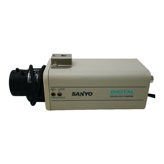
COLOUR CCD camera
CCD-Farbkamera
Caméra CCD COULEUR
CCD
About this manual
Before installing and using the camera, please read this
manual carefully. Be sure to keep it handy for later reference.
Über diese Bedienungsanleitung
Lesen Sie bitte vor der Montage und dem Inbetriebnehmen der
Kamera zuerst diese Bedienungsanleitung sorgfältig durch und
bewahren Sie sie zum späteren Nachschlagen auf.
A propos de ce manuel
Avant d'installer et d'utiliser la caméra, veuillez lire ce
manuel attentivement. Gardez-le à portée de main
pour toute référence ultérieure.
VCC-6570P
Advertisement
Table of Contents

Related Manuals for Sanyo VCC-6570P


Summary of Contents for Sanyo VCC-6570P
- Page 1 INSTRUCTION MANUAL VCC-6570P BEDIENUNGSANLEITUNG MANUEL D’INSTRUCTIONS COLOUR CCD camera CCD-Farbkamera Caméra CCD COULEUR About this manual A propos de ce manuel Before installing and using the camera, please read this Avant d’installer et d’utiliser la caméra, veuillez lire ce manual carefully. Be sure to keep it handy for later reference.
-
Page 2: Table Of Contents
Depending on the conditions of use, installation and environment, FEATURES please be sure to make the appropriate settings and adjustments. If you need help with installation and/or settings, please consult your dealer. • Built-in interline transfer method 1/3" CCD, approx. 470,000 CONTENTS picture elements •... -
Page 3: Precautions
Disconnect the power greasy smoke or steam, where the dampness may get too high, or cord immediately, and consult your dealer (or a Sanyo Authorized where there is a lot of dust. -
Page 4: Parts Names
PARTS NAMES Power indicator (POWER) Comes on when the power to the camera is on. Video output connector (VIDEO OUT: BNC type) Connect this connector to a device such as a VCR or monitor with a VIDEO IN connector. AC power cord External sync composite video signal input connector (VBS IN: BNC type) Connect to this connector the synchronizing signal output from a synchronizing signal device or the composite... - Page 5 PARTS NAMES Lens mount cap The cap is installed to protect the lens mount section. Remove the lens mount cap before installing a lens (sold separately). Flange-back adjustment screw (FLANGE BACK ADJ.) Flange-back lock screw (FLANGE BACK LOCK) Camera installation bracket The bracket can be fixed at the top or bottom of the camera.
- Page 6 PARTS NAMES Lens iris output connector (LENS) This 4-pin connector is used to send the DC control signal and power supply to an auto-iris type lens. Camera setup section (under the cover) These settings are for when using a 1/3 inch CS mount DC (without EE internal amplifier) type lens. However, if due to installation conditions or environment the settings may need to be modified for best results (see "SETTINGS").
-
Page 7: Concerning Auto-Iris Lenses
ALC and LEVEL volume level controls are available on the lens for iris adjustments. (Set the A.I. LENS switch to the VIDEO position.) Compatible auto-iris lenses 1/3 inch Sanyo DC type lens VIDEO type lens VCL-CS8LY: Standard angle, f= 8 mm... -
Page 8: Mounting The Lens
MOUNTING THE LENS Please use a DC type auto-iris lens (sold separately). Check the lens mount Do not use a lens if the length “ ” is more than mm. That may damage the camera and prevent proper installation. C mount type lens Remove the lens mount cap from the camera. - Page 9 MOUNTING THE LENS Rewiring the lens cable in the lens iris plug Prepare the lens cable. Cut the cable at the plug, then remove approx. 8 mm of the cable sheath and strip about 2 mm from each wire. Install the lens iris plug. Solder the cable to the pins following the correct pin layout (refer to the table and illustrations), then close the plug cover.
-
Page 10: Connections
CONNECTIONS (Video signal connections) : VIDEO IN : VIDEO OUT Coaxial cable type and maximum length Basic connection for monitoring or recording • Cable type RG-59U (3C-2V), 250 m maximum. The peripheral devices (VCR, monitor, lens, etc.) and cables are •... - Page 11 CONNECTIONS (Video signal connections) : VIDEO IN : VIDEO OUT CAUTION: Connections to the camera Y/C OUT connector • Please use a monitor with a Y/C or S-VIDEO input terminal, or a The peripheral devices (VCR, monitor, lens, etc.) and cables are time lapse VCR with a S-VIDEO input terminal.
-
Page 12: Settings
SETTINGS The illustration shows the factory default settings for the switches in the camera setup section. The camera settings are described on the assumption that a DC type auto iris lens is being used. If you are using a VIDEO type auto iris lens, be sure to read the Note which is given. - Page 13 SETTINGS High speed electronic shutter setting Iris function setting Normally, the speed setting switches for the high speed electronic This should normally be set to the down (AI) position. shutter are all set to the down (OFF) position. This sets the electronic Use a manual or fixed iris lens and set the lens aperture shutter speed to 1/50 sec.
- Page 14 SETTINGS (MULTI mode: 64 sections) Backlight compensation setting This camera has two different backlight compensation functions: Normally backlight compensation switch 6 (MULT) and 7 (CENT) are set to the down (OFF) position. Change the backlight compensation switch settings depending on the conditions. •...
-
Page 15: White Balance Adjustment
SETTINGS White balance adjustment Line phase adjustment Normally the switch 8 (WB) is set to the down (ATW: auto white When using a camera switcher to connect 2 cameras or more to one balance) position and the white balance is adjusted automatically. If a monitor, there may be a vertical roll of the images when switched. - Page 16 SETTINGS External sync adjustment (VBS) Lens iris adjustment If using a DC type auto-iris lens, you will need to set the LEVEL Connect the VBS signal output for the other camera to the VBS (VR301) volume when shooting in the conditions described below. IN connector at the rear of this camera.
-
Page 17: Troubleshooting
This camera is a precision instruments and if treated with care, will provide years of satisfactory performance. However, in the event of a problem, the owner is advised not to attempt to make repairs or open the cabinet. Servicing should always be referred to your dealer or Sanyo Authorized Service Centre. -
Page 18: Specifications
SPECIFICATIONS Camera: Scanning system Environmental conditions PAL standard Temperature: –10˚C ~ +50˚C (625 TV lines, 25 frames/sec.) Humidity: less than 90% (no condensation) 220 – 230 V AC ± 10% 50 Hz Interlace PLL 2:1 interlace Power supply Image device 1/3 inch solid state image device CCD Power consumption Approx. - Page 19 SPECIFICATIONS Dimensions 1/4”–20 UNC Features and specifications are subject to change without prior notice or obligations. English...
- Page 20 Sanyo Electric Co, Ltd. 1AC6P1P2453-- Printed in Japan L53T5/XE (0801KPS-DSP)