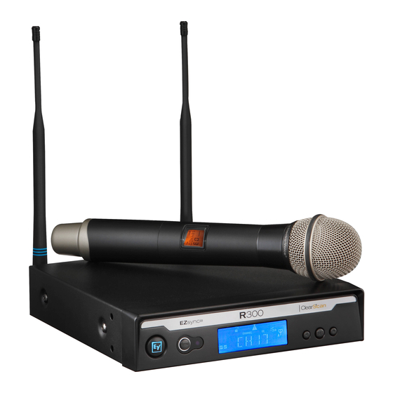
Electro-Voice R300 User Manual
Uhf wireless microphone
Hide thumbs
Also See for R300:
- User manual (36 pages) ,
- Quick start manual (2 pages) ,
- User manual (14 pages)

Related Manuals for Electro-Voice R300


Summary of Contents for Electro-Voice R300
- Page 1 R300 UHF WIRELESS MICROPHONE USER GUIDE R300 Electro-Voice EZsync ClearScan SYNC...
-
Page 3: Table Of Contents
TABLE OF CONTENTS 1. Quick System Setup • Receiver ....................... . . •... -
Page 4: Receiver
QUICK SET-UP: RECEIVER 1. Do not connect the receiver to any other equipment yet! 2. Connect the two Antennas to the receiver. 3. Install the blades into the power supply, plug it into the back of the receiver, and into an outlet. 4. -
Page 5: Transmitter
1. With the Power switch on the transmitter OFF, install two fresh AA batteries into the transmitter. 2. Press the transmitter Power Switch until the display comes on. 3. Hold the transmitter with the EZsync Port facing the receiver, about a foot (30 cm) away. EZsync R300 SYNC ClearScan R300... -
Page 6: Systems Operation
3. You may have to adjust the gain (via the control next to the connector on the receiver back panel) to provide the best input volume for your mixer/amp. “Quick Set-up” is now complete. Please enjoy your R300 system. -
Page 7: Detailed Component Descriptions
DETAILED COMPONENT DESCRIPTIONS 2.1 | R300 Receiver RECEIVER CONTROLS, CONNECTORS 5. Scroll Down and Up ( and ) Control Buttons 1. Power ON/OFF 6. SET Control Button 2. SYNC Data Transfer Button 7. ClearScan Control (press and hold button) 3. Infrared EZsync Window 8. - Page 8 DETAILED COMPONENT DESCRIPTIONS 2.1 | Receiver Setup & Operation 1. Place the receiver and antennas where there is a clear line of sight to the area where the transmitter will be used. Rotate the antennas to separate them by 90 degrees. 2.
- Page 9 EZsync EZsync R300 SYNC R300 ClearScan SYNC ClearScan R300 EZsync R300 Clear EZsync Clear e. Press the SYNC button on the receiver to transfer the channel information. f. The receiver will display SYNC until the data is transferred, then return to the main screen.
- Page 10 6. Plug an audio cable (not supplied) into the 3 pin XLR or ¼ inch output of the R300. Note: The XLR connector is the preferred connection since the output is balanced and will be more immune to noise for longer runs of cable although either can be used with good results.
- Page 11 7. With the transmitter on, speak into the microphone or play the guitar. Turn up the level on the mixer or amplifier until you are able to hear the desired signal. If no audio is present, repeat setup and refer to the troubleshooting section. Note: It may be necessary to adjust the receiver output until the volume level from the wireless system approximates the level of an equivalent wired microphone/instrument.
- Page 12 DETAILED COMPONENT DESCRIPTIONS 9. Change Lock-Out This feature can be useful when the receiver is in a location where unauthorized personnel have access to the receiver. With the LOCK ON, the channel cannot be changed and the word LOCK is displayed when the button is pushed.
- Page 13 10. Squelch Adjustment – The squelch setting can be used to maximize range or immunity to noise. a. Turn the transmitter off. b. Press and hold the SET button until DISPLY shows in the display. c. Press two times to display SQELCH. d.
- Page 14 DETAILED COMPONENT DESCRIPTIONS 2.1.2 | Receiver Main Operating Screen Display: 1. RF Signal Meter 2. Audio Meter 3. Lock Indicator 4. No Signal Indicator 5. Channel Number (01 to 32) or Frequency 6. Squelch Setting 7. Antenna Diversity Status A or B antenna Controls: 1.
-
Page 15: Handheld Transmitter
2.2 | Handheld Transmitter HT-300 CONTROLS, CONNECTORS AND INDICATORS 1. Microphone Element 2. Backlit LCD Display a. Channel b. Frequency c. Battery Level d. Mute Indicator 3. EZSync Infrared Port 4. Battery Cover – Screw type. 5. Battery Compartment – Two AA Batteries 6. -
Page 16: Handheld Transmitter
DETAILED COMPONENT DESCRIPTIONS 2.2 | Handheld Transmitter Setup & Operation 1. Insert Batteries. a. Remove the battery compartment cover by unscrewing it completely. b. Insert two AA batteries as shown, sliding one up into the housing to make room for the other. -
Page 17: Bodypack Transmitter
5. Mute Function – press and hold on/off button for 2 seconds until MUTE appears in the LCD Display between the Channel and Frequency. The sound is then muted. Repeat to turn mute off. 2.3 | Bodypack Transmitter BP-300 CONTROLS, CONNECTORS AND INDICATORS 1. - Page 18 DETAILED COMPONENT DESCRIPTIONS 2.3 | Bodypack Transmitter continued 5. LCD Display a. Channel b. Frequency c. Battery Level d. Mute Indicator 6. EZsync infrared window 7. Battery Compartment Latch – push down latch and slide cover as shown. 8. Two AA Battery Compartment – follow polarity as marked 9.
-
Page 19: Bodypack Transmitter
2.3.1 | Bodypack Transmitter Setup & Operation 1. Insert Batteries a. Open the battery compartment by pressing in on the latch and sliding the door down. b. Insert two AA batteries with + and – as indicated. c. Close the battery door by pushing up. 2. - Page 20 The transmitter and receiver must be of the same frequency band and set to the same channel in order to work together. The R300 is available in three frequency bands, A, B and E (Europe only). The band information is available in the label on the bottom of the receiver, the label in the battery compartment of the handheld transmitter, and on the back panel label in the bodypack.
- Page 21 Battery Recommendations Fresh AA alkaline batteries from a quality manufacturer will yield the best performance from your R300 transmitters. If sound quality degrades during use, it may be the result of a weakening battery.
-
Page 22: Troubleshooting Guide
Change the bodypack gain switch to INS Battery level low in transmitter Insert fresh batteries in transmitter Another R300 system in the installation Make certain all units are on different channels. If Interference is on the same channel or signals... - Page 23 Problem Possible Causes Solutions Another wireless product in the area is Use ClearScan to change the operating frequency. on the same frequency or the signals If problems persist, call EV at 800-392-3497 for are mixing coordination help Receiver is too close to digital signal Move the receiver to a different location processor or similar device Interference...
-
Page 24: Specifications
SPECIFICATIONS R300 Receiver Receiver Type Synthesized PLL A Band 618 – 634MHz Frequency Range (RF) B Band 678 – 694 MHz E Band 850 – 865 MHz Number of Channels Modulation +/- 40 kHz Diversity Antenna RF Sensitivity < 1.0 μV for 12 dB SINAD Image Rejection >... - Page 25 Audio Parameters Frequency Response 80 – 18kHz +/- 2dB Balanced Output 20 dBV (max @ 40 kHz deviation) Unbalanced Output Adjustable 8 mV to 0.755V RMS Distortion < 1.0%, 0.4% typical (ref 1kHz, 40kHz deviation) Signal-to-Noise Ratio > 100dB A Weighted Dynamic Range >...
-
Page 26: Certifications
(Depending on frequency selected and country of operation) R300 receiver, HT-300 and BP-300 transmitters: Certified to ETSI EN 300 422-2 and ETSI EN 301 489-3, Conforms to European Union directives, eligible to bear CE marking as per the R&TTE directive. -
Page 27: Service And Warranty
FACTORY SERVICE Factory Service (North America) If factory service is required, ship the unit prepaid in its original carton to: EV Audio Service c/o Bosch Security Systems, Inc. 8601 East Cornhusker Highway Lincoln, NE 68507-9702 U.S.A. Tel: 402-467-5321 or 800-553-5992 Fax: 402-467-3279 Enclose a note describing the problem along with any other pertinent information and how to contact you. -
Page 28: Components And Accessories
ACCESSORIES AND PARTS Accessories and Parts Model # Order # R300-L System Uni Lapel ULM18 F.01U.168.803 R300-E System Headworn Microphone F.01U.168.804 Windscreen for ULM18 WS-18 F.01U.168.802 Windscreen for HM3 WS-H3 Beltclip for BP-300 BC-300 F.01U.168.797 Guitar Cord MAC-G3 F.01U.118.492 PL22 Dyanmic Mic Head... -
Page 29: Appendix A Compatible Channel Groups
APPENDIX A COMPATIBLE CHANNEL GROUPS (Use only channels within the same group when using more than two R300 units in one room. If you need additional help call 1-800-392-3497 (US and Canada only). US/EURO Band A 618-634 MHz Group 1... - Page 30 APPENDIX A COMPATIBLE CHANNEL GROUPS US/EURO Band B 678-694 MHz Group 1 Group 2 Group 3 Group 4 Channel Freq Channel Freq Channel Freq Channel Freq 678.500 678.900 679.300 679.700 682.700 680.100 680.500 680.900 684.400 681.500 681.900 682.300 688.300 683.100 683.500 683.900 688.800...
- Page 31 APPENDIX A COMPATIBLE CHANNEL GROUPS Euro Band E 850-665 MHz Group 1 Group 2 Group 3 Group 4 Channel Freq Channel Freq Channel Freq Channel Freq 850.400 850.800 851.200 850.000 851.600 852.000 852.400 854.200 853.000 853.400 853.800 855.900 854.600 855.000 855.400 859.800 856.400...
- Page 32 Headquarters in Americas and Asia and Pacific Rim addresses Americas: France: Japan: Headquarters Americas EVI Audio France S.A., EVI Audio Japan, Ltd Bosch Security Systems, Inc. Parc de Courcerin, 5-3-8 Funabashi, Setagaya-ku, 12000 Portland Ave South, Allée Lech Walesa, Tokyo 156-0055 Burnsville, MN 55337, USA F 77185 Lognes, France Tel: +81 (3) 5316-5021...