Table of Contents
Advertisement
Quick Links
Advertisement
Table of Contents

Related Manuals for Asus A58M-A/USB3


Summary of Contents for Asus A58M-A/USB3
- Page 1 A58M-A/USB3...
- Page 2 Product warranty or service will not be extended if: (1) the product is repaired, modified or altered, unless such repair, modification of alteration is authorized in writing by ASUS; or (2) the serial number of the product is defaced or missing. ASUS PROVIDES THIS MANUAL “AS IS” WITHOUT WARRANTY OF ANY KIND, EITHER EXPRESS OR IMPLIED, INCLUDING BUT NOT LIMITED TO THE IMPLIED WARRANTIES OR CONDITIONS OF MERCHANTABILITY OR FITNESS FOR A PARTICULAR PURPOSE. IN NO EVENT SHALL ASUS, ITS...
-
Page 3: Table Of Contents
Contents Safety information ...................... iv About this guide ......................iv Package contents ....................... vi A58M-A/USB3 specifications summary ..............vi Chapter 1: Product introduction Before you proceed ..................1-1 Motherboard overview ................. 1-2 Accelerated Processing Unit (APU) ............1-4 System memory .................... 1-7 Expansion slots .................... -
Page 4: Safety Information
Safety information Electrical safety • To prevent electrical shock hazard, disconnect the power cable from the electrical outlet before relocating the system. • When adding or removing devices to or from the system, ensure that the power cables for the devices are unplugged before the signal cables are connected. If possible, disconnect all power cables from the existing system before you add a device. • Before connecting or removing signal cables from the motherboard, ensure that all power cables are unplugged. • Seek professional assistance before using an adapter or extension cord. These devices could interrupt the grounding circuit. Ensure that your power supply is set to the correct voltage in your area. If you are not • sure about the voltage of the electrical outlet you are using, contact your local power company. • If the power supply is broken, do not try to fix it by yourself. Contact a qualified service technician or your retailer. -
Page 5: Conventions Used In This Guide
Where to find more information Refer to the following sources for additional information and for product and software updates. ASUS websites The ASUS website provides updated information on ASUS hardware and software products. Refer to the ASUS contact information. Optional documentation Your product package may include optional documentation, such as warranty flyers, that may have been added by your dealer. These documents are not part of the standard package. Conventions used in this guide To ensure that you perform certain tasks properly, take note of the following symbols used throughout this manual. DANGER/WARNING: Information to prevent injury to yourself when trying to complete a task. CAUTION: Information to prevent damage to the components when trying to complete a task IMPORTANT: Instructions that you MUST follow to complete a task. . NOTE: Tips and additional information to help you complete a task. -
Page 6: Package Contents
Supports AMD Memory Profile (AMP) memory • The maximum 32GB memory capacity can be supported with 16GB or above DIMMs. ASUS will update the memory QVL once the DIMMs are available in the market. • Hyper DIMM support is subject to the physical characteristics of individual APUs. -
Page 7: Asus Exclusive Features
A58M-A/USB3 specifications summary Expansion slots 1 x PCIe 3.0/2.0 x16 slot* 1 x PCIe 2.0 x1 slot 1 x PCI slot • PCIe 3.0 is supported by FM2+ processors only. Storage / RAID A58 FCH: ® - 6 x Serial ATA 3.0Gb/s connectors support RAID 0, RAID 1, RAID 10 and JBOD configurations Realtek 8111GR PCIe Gigabit LAN controller ® Audio Realtek ALC887-VD 7.1-channel High Definition Audio CODEC ®... - Page 8 A58M-A/USB3 specifications summary Back Panel I/O 1 x PS/2 mouse port (green) ports 1 x PS/2 keyboard port (purple) 1 x HDMI port 1 x DVI-D port 1 x D-Sub output port 1 x LAN (RJ-45) port 2 x USB 3.0/2.0 ports 2 x USB 2.0/1.1 ports 7.1-channel audio I/O ports (3-jack) Internal I/O 2 x USB 2.0/1.1 connectors support additional 4 USB 2.0/1.1 ports connectors 6 x SATA 3.0Gb/s connectors 1 x COM connector 1 x System panel connector 1 x Internal speaker connector 1 x CPU fan connector (4-pin) 1 x S/PDIF output connector 1 x Chassis fan connector (4-pin) 1 x TPM connector 1 x Front panel audio connector 1 x 24-pin EATX power connector 1 x 4-pin ATX 12V power connector BIOS 64 Mb Flash ROM, UEFI AMI BIOS, PnP, DMI 2.0, WfM 2.0, SM BIOS 2.7, ACPI 2.0a, Multi-language BIOS, ASUS EZ Flash 2, ASUS CrashFreen BIOS 3, F12 Printscreen function, F3 Shortcut function and ASUS DRAM SPD (Serial Presence Detect) memory information Support DVD Drivers ASUS Update...
-
Page 9: Chapter 1: Product Introduction
Product introduction Before you proceed Take note of the following precautions before you install motherboard components or change any motherboard settings. • Unplug the power cord from the wall socket before touching any component. • Before handling components, use a grounded wrist strap or touch a safely grounded object or a metal object, such as the power supply case, to avoid damaging them due to static electricity. • Hold components by the edges to avoid touching the ICs on them. • Whenever you uninstall any component, place it on a grounded antistatic pad or in the bag that came with the component. • Before you install or remove any component, ensure that the ATX power supply is switched off or the power cord is detached from the power supply. Failure to do so may cause severe damage to the motherboard, peripherals, or components. ASUS A58M-A/USB3... -
Page 10: Motherboard Overview
Before you install the motherboard, study the configuration of your chassis to ensure that the motherboard fits into it. Ensure that you unplug the power cord before installing or removing the motherboard. Failure to do so can cause you physical injury and damage motherboard components. 1.2.1 Placement direction When installing the motherboard, ensure that you place it into the chassis in the correct orientation. The edge with external ports goes to the rear part of the chassis as indicated in the image below. 1.2.2 Screw holes Place six screws into the holes indicated by circles to secure the motherboard to the chassis. Do not overtighten the screws! Doing so can damage the motherboard. Place this side towards the rear of the chassis A58M-A/USB3 Chapter 1: Product introduction... -
Page 11: Motherboard Layout
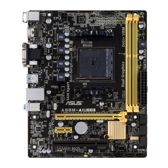
1.2.3 Motherboard layout 18.3cm(7.2in) CPU_FAN CHA_FAN KBMS DIGI +VRM ATX12V USB1112 LAN_USB12 1042 AUDIO A58M-A/USB3 8111 PCIEX16 Super BATTERY ® PCIEX1_1 SPEAKER F_PANEL PCI1 64Mb BIOS SPDIF_OUT USB56 USB34 SATA3G_1 SATA3G_2 SATA3G_3 AAFP 11 10 Connectors/Jumpers/Slots Page 1. Keyboard and USB device wake up (3-pin KB_USBPWB) 1-12 2. ATX power connectors (24-pin EATXPWR, 4-pin ATX12V) -
Page 12: Accelerated Processing Unit (Apu)
Accelerated Processing Unit (APU) This motherboard comes with an FM2+ socket designed for AMD A-series / Athlon™ series ® accelerated processors with AMD Radeon™ R/HD 8000/7000 series graphics. ® A58M-A/USB3 A58M-A/USB3 CPU socket FM2+ Ensure that you use an APU designed for the FM2+ socket. The APU fits in only one correct orientation. DO NOT force the APU into the socket to prevent bending the pins and damaging the APU! 1.3.1 Installing the APU Chapter 1: Product introduction... -
Page 13: Apu Heatsink And Fan Assembly Installation
1.3.2 APU heatsink and fan assembly installation Apply the Thermal Interface Material to the APU heatsink and APU before you install the heatsink and fan if necessary. To install the APU heatsink and fan assembly ASUS A58M-A/USB3... - Page 14 To uninstall the APU heatsink and fan assembly Chapter 1: Product introduction...
-
Page 15: System Memory
Channel Sockets Channel A DIMM_A1 Channel B DIMM_B1 A58M-A/USB3 A58M-A/USB3 240-pin DDR3 DIMM sockets 1.4.2 Memory configurations You may install 1GB, 2GB, 4GB, and 8GB unbuffered non-ECC DDR3 DIMMs into the DIMM sockets. • You may install varying memory sizes in Channel A and Channel B. The system maps the total size of the lower-sized channel for the dual-channel configuration. Any excess memory from the higher-sized channel is then mapped for single-channel operation. -
Page 16: Installing A Dimm
The default memory operation frequency is dependent on its Serial Presence Detect (SPD), which is the standard way of accessing information from a memory module. Under the default state, some memory modules for overclocking may operate at a lower frequency than the vendor-marked value. To operate at the vendor-marked or at a higher frequency, refer to section 2.5 Ai Tweaker menu for manual memory frequency adjustment. • For system stability, use a more efficient memory cooling system to support a full memory load (2 DIMMs) or overclocking condition. • Refer to www.asus.com for the latest Memory QVL (Qualified Vendors List). 1.4.3 Installing a DIMM Chapter 1: Product introduction... -
Page 17: Expansion Slots
To remove a DIMM Expansion slots In the future, you may need to install expansion cards. The following sub-sections describe the slots and the expansion cards that they support. Unplug the power cord before adding or removing expansion cards. Failure to do so may cause you physical injury and damage motherboard components. 1.5.1 Installing an expansion card To install an expansion card: Before installing the expansion card, read the documentation that came with it and make the necessary hardware settings for the card. Remove the system unit cover (if your motherboard is already installed in a chassis). Remove the bracket opposite the slot that you intend to use. Keep the screw for later use. Align the card connector with the slot and press firmly until the card is completely seated on the slot. Secure the card to the chassis with the screw you removed earlier. Replace the system cover. ASUS A58M-A/USB3... -
Page 18: Configuring An Expansion Card
1.5.2 Configuring an expansion card After installing the expansion card, configure it by adjusting the software settings. Turn on the system and change the necessary BIOS settings, if any. See Chapter 2 for information on BIOS setup. Assign an IRQ to the card. Install the software drivers for the expansion card. When using PCI cards on shared slots, ensure that the drivers support “Share IRQ” or that the cards do not need IRQ assignments. Otherwise, conflicts will arise between the two PCI groups, making the system unstable and the card inoperable. 1.5.3 PCI slot The PCI slot supports cards such as a LAN card, SCSI card, USB card, and other cards that comply with PCI specifications. -
Page 19: Jumpers
Jumpers Clear RTC RAM (3-pin CLRTC) This jumper allows you to clear the Real Time Clock (RTC) RAM in CMOS. You can clear the CMOS memory of date, time, and system setup parameters by erasing the CMOS RTC RAM data. The onboard button cell battery powers the RAM data in CMOS, which include system setup information such as system passwords. CLRTC A58M-A/USB3 Normal Clear RTC (Default) A58M-A/USB3 Clear RTC RAM To erase the RTC RAM: Turn OFF the computer and unplug the power cord. Move the jumper cap from pins 1-2 (default) to pins 2-3. Keep the cap on pins 2-3 for about 5-10 seconds, then move the cap back to pins 1-2. Plug the power cord and turn ON the computer. Hold down the <Del> key during the boot process and enter BIOS setup to re- enter data. Except when clearing the RTC RAM, never remove the cap on CLRTC jumper default position. Removing the cap will cause system boot failure! • If the steps above do not help, remove the onboard battery and move the jumper again to clear the CMOS RTC RAM data. After clearing the CMOS, reinstall the battery. • You do not need to clear the RTC when the system hangs due to overclocking. For system failure due to overclocking, use the CPU Parameter Recall (C.P.R.) feature. Shut down and reboot the system, then the BIOS automatically resets parameter settings to default values. ASUS A58M-A/USB3 1-11... -
Page 20: Usb Device Wake-Up
+5VSB lead for each USB port; otherwise, the system would not power up. • The total current consumed must NOT exceed the power supply capability (+5VSB) whether under normal condition or in sleep mode. Keyboard and USB device wake up (3-pin KB_USBPWB) This jumper allows you to enable or disable the keyboard and USB device wake-up feature. When you set this jumper to pins 2-3 (+5VSB), you can wake up the computer by pressing a key on the keyboard. This feature requires an ATX power supply that can supply at least 1A on the +5VSB lead, and a corresponding setting in the BIOS. KB_USBPWB A58M-A/USB3 +5VSB (Default) A58M-A/USB3 Keyboard and USB device wake-up Chapter 1: Product introduction 1-12... -
Page 21: Connectors
Line Out port (lime). This port connects to a headphone or a speaker. In the 4.1, 5.1, and 7.1-channel configurations, the function of this port becomes Front Speaker Out. Microphone port (pink). This port connects to a microphone. Refer to the audio configuration table below for the function of the audio ports in 2.1, 4.1, 5.1, or 7.1-channel configuration. ASUS A58M-A/USB3 1-13... -
Page 22: Internal Connectors
DVI-D port. This port is for any DVI-D compatible device. DVI-D can’t be converted to output RGB Signal to CRT and isn’t compatible with DVI-I. PS/2 Keyboard port (purple). This port is for a PS/2 keyboard. 1.7.2 Internal connectors TPM connector (20-1 pin TPM) This connector supports a Trusted Platform Module (TPM) system, which can securely store keys, digital certificates, passwords and data. A TPM system also helps enhance network security, protects digital identities, and ensures platform integrity. PIN 1 A58M-A/USB3 A58M-A/USB3 TPM connector Chapter 1: Product introduction 1-14... - Page 23 A58M-A/USB3 HD-audio-compliant Legacy AC’97 pin definition compliant definition A58M-A/USB3 Front panel audio connector • We recommend that you connect a high-definition front panel audio module to this connector to avail of the motherboard high-definition audio capability. • If you want to connect a high definition front panel audio module to this connector, set the Front Panel Type item in the BIOS to [HD].
-
Page 24: Atx Power Connectors
+5 Volts PSON# +5 Volts A58M-A/USB3 +3 Volts -12 Volts +3 Volts +3 Volts PIN 1 A58M-A/USB3 ATX power connectors • We recommend that you use an ATX 12V Specification 2.0-compliant power supply unit (PSU) with a minimum of 300W power rating. This PSU type has 24-pin and 4-pin power plugs. • If you intend to use a PSU with 20-pin and 4-pin power plugs, ensure that the 20-pin power plug can provide at least 15 A on +12 V and that the PSU has a minimum power rating of 300W. The system may become unstable or may not boot up if the power is inadequate. - Page 25 SATA3G_5 RSATA_TXP5 RSATA_TXN5 RSATA_RXN5 RSATA_RXP5 SATA3G_4 RSATA_TXP4 RSATA_TXN4 SATA3G_1 SATA3G_2 SATA3G_3 RSATA_RXN4 RSATA_RXP4 A58M-A/USB3 A58M-A/USB3 SATA 3.0Gb/s connectors • These connectors are set to AHCI mode by default. If you intend to create a Serial ATA RAID set using these connectors, set the OnChip SATA Type item in the BIOS to [RAID]. See section 2.6.2 SATA Configuration for details. • You must install Windows XP Service Pack 3 or later version before using Serial ® ATA hard disk drives. The Serial ATA RAID feature is available only if you are using Windows XP SP3 or later version. ® When using hot-plug and NCQ, set the OnChip SATA Type item in the BIOS to •...
-
Page 26: Speaker Connector 4-Pin Speaker
System panel connector (10-1 pin PANEL) This connector supports several chassis-mounted functions. F_PANEL +PWR LED PWR BTN PIN 1 A58M-A/USB3 +HDD_LED RESET A58M-A/USB3 System panel connector • System power LED (2-pin PWR_LED) This 2-pin connector is for the system power LED. Connect the chassis power LED cable to this connector. The system power LED lights up when you turn on the system power, and blinks when the system is in sleep mode. • Hard disk drive activity LED (2-pin HDD_LED) This 2-pin connector is for the HDD Activity LED. Connect the HDD Activity LED cable to this connector. The HDD LED lights up or flashes when data is read from or written to the HDD. - Page 27 These USB connectors comply with USB 2.0 specification that supports up to 480Mbps connection speed. USB56 USB34 A58M-A/USB3 PIN 1 PIN 1 A58M-A/USB3 USB2.0 connectors Never connect a 1394 cable to the USB connectors. Doing so will damage the motherboard! The USB 2.0 module is purchased separately. Serial port connector (10-1 pin COM) This connector is for a serial (COM) port. Connect the serial port module cable to this connector, then install the module to a slot opening at the back of the system chassis. PIN 1 A58M-A/USB3 A58M-A/USB3 Serial port connectors The COM module is purchased separately. ASUS A58M-A/USB3 1-19...
-
Page 28: Software Support
• Only motherboards installed with an AMD Trinity APU support Windows Vista / 64bit ® Windows Vista operaing system. ® 1.8.2 Support DVD information The Support DVD that comes with the motherboard package contains the drivers, software applications, and utilities that you can install to avail all motherboard features. The contents of the Support DVD are subject to change at any time without notice. Visit the ASUS website at www.asus.com for updates. To run the Support DVD Place the Support DVD into the optical drive. If Autorun is enabled in your computer, the DVD automatically displays the Specials screen which contains the unique features of ASUS motherboard. Click Drivers, Utilities, Make Disk, Manual, Contact and Specials tabs to display their respective menus. The following screen is for reference only. Click an icon to display Support DVD/motherboard information Click an item to install If Autorun is NOT enabled in your computer, browse the contents of the Support DVD to locate the file ASSETUP.EXE from the BIN folder. Double-click the ASSETUP.EXE to run the DVD. -
Page 29: Chapter 2: Bios Information
EZ Update EZ Update is a utility that allows you to automatically update your motherboard’s softwares, drivers and the BIOS version easily. With this utlity, you can also manually update the saved BIOS and select a boot logo when the system goes into POST. To launch EZ Update, click EZ Update on the AI Suite 3 main menu bar. Click to automatically update your motherboard’s driver, software and firmware Click to find and Click to select Click to select the BIOS a boot logo update the from file BIOS EZ Update requires an Internet connection either through a network or an ISP (Internet Service Provider). ASUS A58M-A/USB3... -
Page 30: Asus Ez Flash
ASUS EZ Flash 2 The ASUS EZ Flash 2 feature allows you to update the BIOS without using an OS-based utility. Before you start using this utility, download the latest BIOS file from the ASUS website at www.asus.com. To update the BIOS using EZ Flash 2: Insert the USB flash disk that contains the latest BIOS file to the USB port. -
Page 31: Asus Crashfree Bios 3 Utility
2.1.3 ASUS CrashFree BIOS 3 utility The ASUS CrashFree BIOS 3 is an auto recovery tool that allows you to restore the BIOS file when it fails or gets corrupted during the updating process. You can restore a corrupted BIOS file using the motherboard support DVD or a USB flash drive that contains the updated BIOS file. - Page 32 Select the USB flash drive as the boot device. The DOS screen appears. Updating the BIOS file To update the BIOS file using BIOS Updater: At the FreeDOS prompt, type bupdater /pc /g and press <Enter>. The BIOS Updater screen appears as below. ASUSTek BIOS Updater for DOS V1.30 A58M-A/USB3 0302 01/20/2014 A58MAU3.CAP 8194 2014-01-20 15:25:48 Chapter 2: BIOS information...
- Page 33 • For BIOS Updater version 1.30 or later, the utility automatically exits to the DOS prompt after updating BIOS. • Ensure to load the BIOS default settings to ensure system compatibility and stability. Select the Load Optimized Defaults item under the Exit menu. Refer to section 2.10 Exit menu for details. • Ensure to connect all SATA hard disk drives after updating the BIOS file if you have disconnected them. ASUS A58M-A/USB3...
-
Page 34: Bios Setup Program
BIOS setup program Use the BIOS Setup program to update the BIOS or configure its parameters. The BIOS screens include navigation keys and brief online help to guide you in using the BIOS Setup program. Entering BIOS Setup at startup To enter BIOS Setup at startup: • Press <Delete> during the Power-On Self Test (POST). If you do not press <Delete>, POST continues with its routines. Entering BIOS Setup after POST To enter BIOS Setup after POST: • Press <Ctrl>+<Alt>+<Del> simultaneously. • Press the reset button on the system chassis. • Press the power button to turn the system off then back on. Do this option only if you failed to enter BIOS Setup using the first two options. -
Page 35: Advanced Mode
The Boot Menu(F8) button is available only when the boot device is installed to the • system. Advanced Mode The Advanced Mode provides advanced options for experienced end-users to configure the BIOS settings. The figure below shows an example of the Advanced Mode. Refer to the following sections for the detailed configurations. To access the EZ Mode, click Exit, then select ASUS EZ Mode. ASUS A58M-A/USB3... -
Page 36: Menu Bar
Back button Menu items Menu bar Configuration fields General help Pop-up window Last modified Submenu item Navigation keys settings Quick note Menu bar The menu bar on top of the screen has the following main items: My Favorites For saving the frequently-used system settings and configuration Main For changing the basic system configuration Ai Tweaker For changing the overclocking settings Advanced... -
Page 37: Submenu Items
A configurable field is highlighted when selected. To change the value of a field, select it and press <Enter> to display a list of options. Quick Note button This button allows you to enter notes of the activities that you have done in BIOS. Last Modified button This button shows the items that you last modified and saved in BIOS Setup. ASUS A58M-A/USB3... -
Page 38: My Favorites
My Favorites MyFavorites is your personal space where you can easily save and access your favorite BIOS items. Adding items to My Favorites To add frequently-used BIOS items to My Favorites: Use the arrow keys to select an item that you want to add. When using a mouse, hover the pointer to the item. 2. Press <F4> on your keyboard or right-click on your mouse to add the item to My Favorites page. You cannot add the following items to My Favorites: • Items with submenu options • User-configurable items such as language and boot device order • Configuration items such as Memory SPD Information, system time and date 2-10 Chapter 2: BIOS information... -
Page 39: Main Menu
Allows you to choose the BIOS language version from the options. Configuration options: [English] [Español] [Русский] [한국어] 2.4.2 System Date [Day xx/xx/xxxx] Allows you to set the system date. 2.4.3 System Time [xx:xx:xx] Allows you to set the system time. 2.4.4 Security The Security menu items allow you to change the system security settings. • If you have forgotten your BIOS password, erase the CMOS Real Time Clock (RTC) RAM to clear the BIOS password. See section 1.6 Jumpers for information on how to erase the RTC RAM. The Administrator or User Password items on top of the screen show the default • Not Installed. After you set a password, these items show Installed. ASUS A58M-A/USB3 2-11... -
Page 40: Administrator Password
Administrator Password If you have set an administrator password, we recommend that you enter the administrator password for accessing the system. Otherwise, you might be able to see or change only selected fields in the BIOS setup program. To set an administrator password: Select the Administrator Password item and press <Enter>. From the Create New Password box, key in a password, then press <Enter>. Confirm the password when prompted. To change an administrator password: Select the Administrator Password item and press <Enter>. From the Enter Current Password box, key in the current password, then press <Enter>. From the Create New Password box, key in a new password, then press <Enter>. Confirm the password when prompted. -
Page 41: Ai Tweaker Menu
The Ai Tweaker menu items allow you to configure overclocking-related items. Be cautious when changing the settings of the Ai Tweaker menu items. Incorrect field values can cause the system to malfunction. The configuration options for this section vary depending on the CPU and DIMM model you installed on the motherboard. Scroll down to display the following items: ASUS A58M-A/USB3 2-13... -
Page 42: Dram Timing Control
Target CPU Speed : xxxxMHz Displays the current CPU speed. Target DRAM Speed : xxxxMHz Displays the current DRAM speed. 2.5.1 Memory Frequency [Auto] Allows you to set the memory operating frequency. Configuration options: [Auto] [DDR3- 800MHz] [DDR3-1066MHz] [DDR3-1333MHz] [DDR3-1600MHz] [DDR3-1866MHz] [DDR3- 2133MHz] [DDR3-2400MHz] Selecting a very high memory frequency may cause the system to become unstable! If this happens, revert to the default setting. 2.5.2 APU Multiplier [Auto] Allows you to set the multiplier between the APU Core Clock and the APU Bus Frequency. - Page 43 Configuration options: [100%] [110%] [120%] [130%] CPU Power Phase Control [Standard] Phase number is the number of working VRM phase. Increasing phase number under heavy system loading to get more transient and better thermal performance. Reducing phase number under light system loading to increase VRM efficiency. [Standard] Proceeds phase control depending on the CPU loading. [Optimized] Loads the ASUS optimized phase tuning profile. [Extreme] Proceeds the full phase mode. [Manual Adjustment] Allows manual adjustment. DO NOT remove the thermal module when switching to Extreme and Manual Adjustment. The thermal conditions should be monitored. Manual Adjustment [Fast] This item appears only when you set the previous item to [Manual Adjustment]. Select [Ultra Fast] for a faster response. The reaction time will be longer when [Regular] is selected.
-
Page 44: Advanced Menu
CPU Voltage Frequency [300] Switching frequency will affect the VRM transient response and component thermal. Setting a higher frequency gets faster transient response. Use the <+> and <-> keys to adjust the value. The values range from 200k Hz to 350k Hz with a 50k Hz interval. CPU Power Duty Control [T.Probe] [T.Probe] Maintains the VRM thermal balance. [Extreme] Maintains the VRM current balance. Do not remove the thermal module while changing the DIGI+VRM related parameters. The thermal conditions should be monitored. Advanced menu The Advanced menu items allow you to change the settings for the CPU and other system devices. Be cautious when changing the settings of the Advanced menu items. Incorrect field values can cause the system to malfunction. -
Page 45: Sata Configuration
Allows you to change the number of working Compute Unit on the system. Configuration options: [Automatic mode] [One core per processor] [One Compute Unit] [One core per Compute Unit] 2.6.2 SATA Configuration While entering Setup, the BIOS automatically detects the presence of SATA devices. The SATA Port items show Not Present if no SATA device is installed to the corresponding SATA port. OnChip SATA Channel [Enabled] Enables or disables onboard channel SATA port. Configuration options: [Disabled] [Enabled] ASUS A58M-A/USB3 2-17... -
Page 46: Usb Configuration
OnChip SATA Type [AHCI] Allows you to set the SATA configuration. [IDE] S et to [IDE] when you want to use the Serial ATA hard disk drives as Parallel ATA physical storage devices. [RAID] Set to [RAID] when you want to create a RAID configuration from the SATA hard disk drives. [AHCI] S et to [AHCI] when you want the SATA hard disk drives to use the AHCI (Advanced Host Controller Interface). The AHCI allows the onboard storage driver to enable advanced Serial ATA features that increases storage performance on random workloads by allowing the drive to internally optimize the order of commands. SATA Port 5,6 [AHCI] This item only appears when OnChip SATA Type is set to [AHCI]. If SATA ports 5, 6 are configured as [AHCI], the ports can only be used under Windows... -
Page 47: Onboard Devices Configuration
Allows you to set the front panel audio connector (AAFP) mode to legacy AC’97 or high- definition audio depending on the audio standard that the front panel audio module supports. [HD] Sets the front panel audio connector (AAFP) mode to high definition audio. [AC97] Sets the front panel audio connector (AAFP) mode to legacy AC’97. SPDIF Out Type [SPDIF] [SPDIF] Sets to [SPDIF] for SPDIF audio output. [HDMI] Sets to [HDMI] for HDMI audio output. ASUS A58M-A/USB3 2-19... -
Page 48: Serial Port Configuration
Realtek LAN Controller [Enabled] [Enabled] Enables the Realtek LAN controller. [Disabled] Disables the controller. Realtek PXE OPROM [Disabled] This item appears only when you set the Realtek LAN Controller item to [Enabled] and allows you to enable or disable the Rom of the Realtek LAN controller. Configuration options: [Enabled] [Disabled] Asmedia USB 3.0 Controller [Enabled] [Enabled] Enables the onboard USB 3.0 controller. [Disabled] Disables the controller. Asmedia USB 3.0 Battery Charging Support [Disabled] This item appears only when the Asmedia USB 3.0 Controller item is set to [Enabled]. -
Page 49: Network Stack
Ipv4 PXE Support [Enabled] This item allows user to disable or enable the Ipv4 PXE Boot support. Configuration options: [Disabled] [Enable] Ipv6 PXE Support [Enabled] This item allows user to disable or enable the Ipv6 PXE Boot support. Configuration options: [Disabled] [Enabled] ASUS A58M-A/USB3 2-21... -
Page 50: Monitor Menu
Monitor menu The Monitor menu displays the system temperature/power status, and allows you to change the fan settings. Scroll down to display the following items: 2-22 Chapter 2: BIOS information... - Page 51 Sets to [Silent] to minimize the fan speed for quiet CPU fan operation. [Turbo] Sets to [Turbo] to achieve maximum CPU fan speed. [Manual] Sets to [Manual] to assign detailed fan speed control parameters. The following four items appear only when you set Q-Fan Profile to [Manual]. Q-Fan Upper Temperature [70] Use the <+> and <-> keys to adjust the upper limit of the CPU temperature. The values range from 20ºC to 75ºC. Q-Fan Max. Duty Cycle(%) [100] Use the <+> and <-> keys to adjust the maximum CPU fan duty cycle. The values range from 20% to 100%. When the CPU temperature reaches the upper limit, the CPU fan will operate at the maximum duty cycle. Q-Fan Lower Temperature [20] Use the <+> and <-> keys to adjust the lower limit of the CPU temperature. The values range from 20ºC to 75ºC. Q-Fan Min. Duty Cycle(%) [20] Use the <+> and <-> keys to adjust the minimum CPU fan duty cycle. The values range from 20% to 100%. When the CPU temperature is under the lower limit, the CPU fan will operate at the minimum duty cycle. ASUS A58M-A/USB3 2-23...
- Page 52 2.7.4 Chassis Q-Fan Control [Enabled] [Disabled] Disables the Chassis1 Q-Fan control feature. [Enabled] Enables the Chassis1 Q-Fan control feature. Fan Speed Low Limit [600 RPM] This item appears only when you enable the Chassis1 Q-Fan Control feature and allows you to disable or set the chassis1 fan warning speed. Configuration options: [Ignore] [200RPM] [300 RPM] [400 RPM] [500 RPM] [600 RPM] Q-Fan Profile [Standard] This item appears only when you enable the Chassis1 Q-Fan Control feature and allows you to set the appropriate performance level of the chassis fan. [Standard] Sets to [Standard] to make the chassis fan automatically adjust depending on the chassis temperature. [Silent] Sets to [Silent] to minimize the fan speed for quiet chassis fan operation. [Turbo] Sets to [Turbo] to achieve maximum chassis fan speed.
-
Page 53: Boot Menu
Boot menu The Boot menu items allow you to change the system boot options. Scroll down to display the following items: ASUS A58M-A/USB3 2-25... - Page 54 2.8.1 Fast Boot [Enabled] [Enabled] Select to accelerate the boot speed. [Disabled] Select to go back to normal boot. The following five items appear when you set Fast Boot to [Enabled]. SATA Support [All Devices] [All Devices] A ll devices connected to SATA ports will be available during POST. This process will extend the POST time. [Hard Drive Only] O nly hard drives connected to SATA ports will be detected during POST. Any hardware change will disable fast boot. [Boot Drive Only] O nly boot drive connected to SATA ports will be detected during POST. Any hardware change will disable fast boot. USB Support [Partial Initialization] [Disabled] A ll USB devices will not be available until OS boot up for a fastest POST time.
- Page 55 When this item is set to [Enabled], the system waits for the F1 key to be pressed when error occurs. Configuration options: [Disabled] [Enabled] 2.8.5 Option ROM Messages [Force BIOS] [Force BIOS] The third-party ROM messages will be forced to display during the boot sequence. [Keep Current] The third-party ROM messages will be displayed only if the third-party manufacturer had set the add-on device to do so. 2.8.6 Interrupt 19 Capture [Disabled] [Enabled] Allows the option ROMs to trap Interrupt 19. [Disabled] Disables this function. 2.8.7 Setup Mode [EZ Mode] [Advanced Mode] Sets Advanced Mode as the default screen for entering the BIOS setup program. [EZ Mode] Sets EZ Mode as the default screen for entering the BIOS setup program. ASUS A58M-A/USB3 2-27...
-
Page 56: Secure Boot
2.8.8 CSM (Compatibility Support Module) Allows you to configure the CSM (Compatibility Support Module) items to fully support the various VGA, bootable devices and add-on devices for better compatibility. Launch CSM [Enabled] [Auto] T he system automatically detects the bootable devices and the add-on devices. [Enabled] F or better compatibility, enable the CSM to fully support the non-UEFI driver add-on devices or the Windows UEFI mode. ® [Disabled] D isable the CSM to fully support the Windows Security Update and ® Security Boot. The following four items appear when you set Launch CSM to [Enabled]. Boot Device Control [UEFI and Legacy OpROM] Allows you to select the type of devices that you want to boot up. -
Page 57: Key Management
Allows you to delete the KEK from your system. Configuration options: [Yes] [No] Load KEK from File Allows you to load the downloaded KEK from a USB storage device. Append KEK from file Allows you to load the additional KEK from a storage device for an additional db and dbx loaded management. The KEK file must be formatted as a UEFI variable structure with time-based authenticated variable. ASUS A58M-A/USB3 2-29... -
Page 58: Boot Option Priorities
Append DBX from file Allows you to load the additional DBX from a storage device so that more db’s images cannot be loaded. The DBX file must be formatted as a UEFI variable structure with time-based authenticated variable. 2.8.10 Boot Option Priorities These items specify the boot device priority sequence from the available devices. The number of device items that appears on the screen depends on the number of devices installed in the system. • To select the boot device during system startup, press <F8> when ASUS Logo appears. • To access Windows OS in Safe Mode, press <F8> after POST. 2.8.11 Boot Override These items displays the available devices. The number of device items that appears on the screen depends on the number of devices installed in the system. Click an item to start booting from the selected device. 2-30 Chapter 2: BIOS information... -
Page 59: Tools Menu
The Tools menu items allow you to configure options for special functions. Select an item then press <Enter> to display the submenu. 2.9.1 ASUS EZ Flash 2 Utility Allows you to run ASUS EZ Flash 2. Press [Enter] to launch the ASUS EZ Flash 2 screen. For more details, see section 2.1.2 ASUS EZ Flash 2. 2.9.2 ASUS SPD Information DIMM Slot Number [DIMM_A1] Displays the Serial Presence Detect (SPD) information of the DIMM module installed on the selected slot. Configuration options: [DIMM_A1] [DIMM_B1] 2.9.3... -
Page 60: Exit Menu
This option allows you to exit the Setup program without saving your changes. When you select this option or if you press <Esc>, a confirmation window appears. Select Yes to discard changes and exit. ASUS EZ Mode This option allows you to enter the EZ Mode screen. Launch EFI Shell from filesystem device This option allows you to attempt to launch the UEFI Shell application (shellx64.efi) from one of the available devices that have a filesystem. -
Page 61: Appendices
FCC regulations. Changes or modifications to this unit not expressly approved by the party responsible for compliance could void the user’s authority to operate this equipment. IC: Canadian Compliance Statement Complies with the Canadian ICES-003 Class B specifications. This device complies with RSS 210 of Industry Canada. This Class B device meets all the requirements of the Canadian interference-causing equipment regulations. This device complies with Industry Canada license exempt RSS standard(s). Operation is subject to the following two conditions: (1) this device may not cause interference, and (2) this device must accept any interference, including interference that may cause undesired operation of the device. Cut appareil numérique de la Classe B est conforme à la norme NMB-003 du Canada. Cet appareil numérique de la Classe B respecte toutes les exigences du Règlement sur le matériel brouilleur du Canada. Cet appareil est conforme aux normes CNR exemptes de licence d’Industrie Canada. Le fonctionnement est soumis aux deux conditions suivantes : (1) cet appareil ne doit pas provoquer d’interférences et (2) cet appareil doit accepter toute interférence, y compris celles susceptibles de provoquer un fonctionnement non souhaité de l’appareil. A58M-A/USB3... -
Page 62: Canadian Department Of Communications Statement
Canadian Department of Communications Statement This digital apparatus does not exceed the Class B limits for radio noise emissions from digital apparatus set out in the Radio Interference Regulations of the Canadian Department of Communications. This class B digital apparatus complies with Canadian ICES-003. VCCI: Japan Compliance Statement VCCI Class B Statement KC: Korea Warning Statement REACH Complying with the REACH (Registration, Evaluation, Authorisation, and Restriction of Chemicals) regulatory framework, we published the chemical substances in our products at ASUS REACH website at http://csr.asus.com/english/REACH.htm. DO NOT throw the motherboard in municipal waste. This product has been designed to enable proper reuse of parts and recycling. This symbol of the crossed out wheeled bin indicates that the product (electrical and electronic equipment) should not be placed in municipal waste. Check local regulations for disposal of electronic products. DO NOT throw the mercury-containing button cell battery in municipal waste. This symbol of the crossed out wheeled bin indicates that the battery should not be placed in municipal waste. ASUS Recycling/Takeback Services ASUS recycling and takeback programs come from our commitment to the highest standards for protecting our environment. We believe in providing solutions for you to be able to responsibly recycle our products, batteries, other components as well as the packaging materials. Please go to http://csr.asus.com/english/Takeback.htm for detailed recycling information in different regions. Appendices... -
Page 63: Asus Contact Information
ASUS COMPUTER INTERNATIONAL (America) Address 800 Corporate Way, Fremont, CA 94539, USA Telephone +1-510-739-3777 Fax +1-510-608-4555 Web site http://usa.asus.com Technical Support Support fax +1-812-284-0883 General support +1-812-282-2787 Online support http://support.asus.com/techserv/techserv.aspx ASUS COMPUTER GmbH (Germany and Austria) Address Harkort Str. 21-23, D-40880 Ratingen, Germany Fax +49-2102-959931 Web site http://www.asus.com/de Online contact http://eu-rma.asus.com/sales Technical Support Telephone +49-2102-5789555 Support Fax +49-2102-959911 Online support http://support.asus.com/techserv/techserv.aspx... - Page 64 Appendices...