Table of Contents
Advertisement
Advertisement
Table of Contents

Related Manuals for Asus A58M-K


Summary of Contents for Asus A58M-K
- Page 1 A58M-K...
- Page 2 Product warranty or service will not be extended if: (1) the product is repaired, modified or altered, unless such repair, modification of alteration is authorized in writing by ASUS; or (2) the serial number of the product is defaced or missing.
-
Page 3: Table Of Contents
Contents Safety information ...................... iv About this guide ......................iv Package contents ....................... vi A58M-K specifications summary ................vi Product introduction Before you proceed ..................1-1 Motherboard overview ................. 1-2 Accelerated Processing Unit (APU) ............1-4 System memory .................... 1-7 Expansion slots .................. -
Page 4: Safety Information
Safety information Electrical safety • To prevent electrical shock hazard, disconnect the power cable from the electrical outlet before relocating the system. • When adding or removing devices to or from the system, ensure that the power cables for the devices are unplugged before the signal cables are connected. If possible, disconnect all power cables from the existing system before you add a device. -
Page 5: Conventions Used In This Guide
Refer to the following sources for additional information and for product and software updates. ASUS websites The ASUS website provides updated information on ASUS hardware and software products. Refer to the ASUS contact information. Optional documentation Your product package may include optional documentation, such as warranty flyers, that may have been added by your dealer. -
Page 6: Package Contents
2 x DDR3 DIMM, max. 32GB, DDR3 2400 (O.C.) / 2133 / 1866 / 1600 / 1333 MHz, non-ECC un-buffered memory Dual-channel memory architecture • The maximum 32GB memory capacity can be supported with 16GB or above DIMMs. ASUS will update the memory QVL once the DIMMs are available in the market. • Hyper DIMM support is subject to the physical characteristics of individual APUs. - Page 7 - ASUS AI Charger - ASUS AI Suite 3 - ASUS Anti-Surge Protection ASUS Quiet Thermal Solution - ASUS Fanless Design: Stylish Heatsink Solution - ASUS Fan Xpert ASUS EZ DIY - ASUS UEFI BIOS EZ Mode - ASUS CrashFree BIOS 3 - ASUS EZ Flash 2 - ASUS MyLogo 2™...
- Page 8 A58M-K specifications summary 2 x USB 2.0 connectors support additional 4 USB 2.0 ports Internal I/O connectors 1 x COM connector 4 x SATA 3.0Gb/s connectors 1 x System panel connector 1 x Internal Speaker connector 1 x CPU fan connector...
-
Page 9: Product Introduction
Before you install or remove any component, ensure that the ATX power supply is switched off or the power cord is detached from the power supply. Failure to do so may cause severe damage to the motherboard, peripherals, or components. ASUS A58M-K... -
Page 10: Motherboard Overview
Place six screws into the holes indicated by circles to secure the motherboard to the chassis. Do not overtighten the screws! Doing so can damage the motherboard. Place this side towards the rear of the chassis A58M-K Chapter 1: Product introduction... -
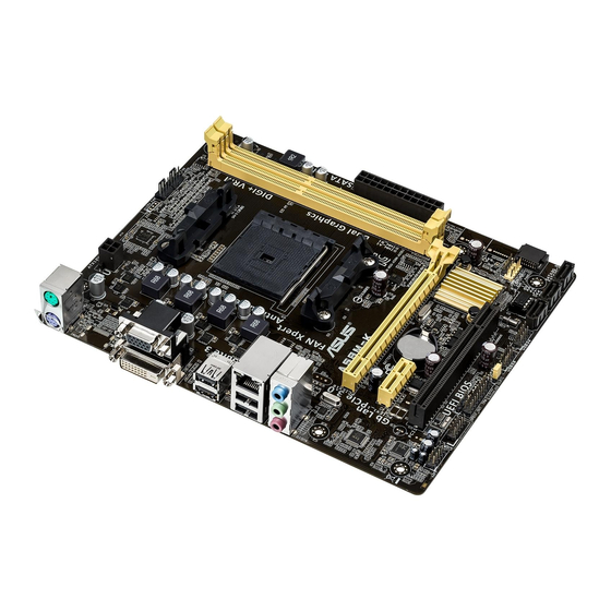
Page 11: Motherboard Layout
10. TPM connector (20-1 pin TPM) 1-18 11. Digital audio connector (4-1 pin SPDIF_OUT) 1-15 12. Serial port connector (10-1 pin COM) 1-16 13. Standby power LED (SB_PWR) 1-19 14. Front panel audio connector (10-1 pin AAFP) 1-18 ASUS A58M-K... -
Page 12: Accelerated Processing Unit (Apu)
A58M-K A58M-K CPU socket FM2+ Ensure that you use an APU designed for the FM2+ socket. The APU fits in only one correct orientation. DO NOT force the APU into the socket to prevent bending the pins and damaging the APU! 1.3.1... -
Page 13: Apu Heatsink And Fan Assembly Installation
1.3.2 APU heatsink and fan assembly installation Apply the Thermal Interface Material to the APU heatsink and APU before you install the heatsink and fan if necessary. To install the APU heatsink and fan assembly ASUS A58M-K... - Page 14 To uninstall the APU heatsink and fan assembly Chapter 1: Product introduction...
-
Page 15: System Memory
DDR2 DIMM socket. DDR3 modules are developed for better performance with less power consumption. The figure illustrates the location of the DDR3 DIMM sockets: Channel Sockets Channel A DIMM_A1 Channel B DIMM_B1 A58M-K A58M-K 240-pin DDR3 DIMM sockets ASUS A58M-K... -
Page 16: Memory Configurations
• The maximum 32GB memory capacity can be supported with 16GB or above DIMMs. ASUS will update the memory QVL once the DIMMs are available in the market. • The default memory operation frequency is dependent on its Serial Presence Detect (SPD), which is the standard way of accessing information from a memory module. - Page 17 1.4.3 Installing a DIMM To remove a DIMM ASUS A58M-K...
-
Page 18: Expansion Slots
Expansion slots In the future, you may need to install expansion cards. The following sub-sections describe the slots and the expansion cards that they support. Unplug the power cord before adding or removing expansion cards. Failure to do so may cause you physical injury and damage motherboard components. -
Page 19: Pci Express X1 Slot
– SATA controller – – – shared – – – – On Chip USB EHCI 1/2/3 – shared – – – – – – On Chip USB OHCI 1/2/3/4 – – shared – – – – – ASUS A58M-K 1-11... -
Page 20: Jumpers
A58M-K Normal Clear RTC (Default) A58M-K Clear RTC RAM To erase the RTC RAM: Turn OFF the computer and unplug the power cord. Move the jumper cap from pins 1-2 (default) to pins 2-3. Keep the cap on pins 2-3 for about 5-10 seconds, then move the cap back to pins 1-2. -
Page 21: Connectors
7.1-channel configurations, the function of this port becomes Front Speaker Out. Microphone port (pink). This port connects to a microphone. Refer to the audio configuration table for the function of the audio ports in 2.1, 4.1, 5.1, or 7.1-channel configuration. ASUS A58M-K 1-13... -
Page 22: Internal Connectors
These are not jumpers! DO NOT place jumper caps on the fan connectors. • The CPU_FAN connector supports a CPU fan of maximum 2A (24 W) fan power. • The CPU_FAN and CHA_FAN connectors support the ASUS Fan Xpert feature. 1-14 Chapter 1: Product introduction... -
Page 23: Atx Power Connectors
• If you are uncertain about the minimum power supply requirement for your system, refer to the Recommended Power Supply Wattage Calculator at http://support.asus. com/PowerSupplyCalculator/PSCalculator.aspx?SLanguage=en-us for details. Digital audio connector (4-1 pin SPDIF_OUT) This connector is for an additional Sony/Philips Digital Interface (S/PDIF) port. - Page 24 RSATA_TXN4 RSATA_TXP4 A58M-K A58M-K SATA 3.0Gb/s connectors • These connectors are set to AHCI mode by default. If you intend to create a Serial ATA RAID set using these connectors, set the type of the SATA connectors in the BIOS to [RAID].
-
Page 25: System Panel Connector
PIN 1 A58M-K +HDD_LED RESET A58M-K System panel connector • System power LED (2-pin PWR_LED) This 2-pin connector is for the system power LED. Connect the chassis power LED cable to this connector. The system power LED lights up when you turn on the system power, and blinks when the system is in sleep mode. - Page 26 A58M-K HD-audio-compliant Legacy AC’97 pin definition compliant definition A58M-K Front panel audio connector • We recommend that you connect a high-definition front panel audio module to this connector to avail of the motherboard high-definition audio capability. • If you want to connect a high definition front panel audio module to this connector, set the Front Panel Type item in the BIOS to [HD].
-
Page 27: Onboard Leds
480Mbps connection speed. USB56 USB34 A58M-K PIN 1 PIN 1 A58M-K USB2.0 connectors Never connect a 1394 cable to the USB connectors. Doing so will damage the motherboard! The USB 2.0 module is purchased separately. Onboard LEDs Standby Power LED The motherboard comes with a standby power LED that lights up to indicate that the system is ON, in sleep mode, or in soft-off mode. -
Page 28: Software Support
Place the Support DVD into the optical drive. If Autorun is enabled in your computer, the DVD automatically displays the Specials screen which contains the unique features of ASUS motherboard. Click Drivers, Utilities, Make Disk, Manual, Contact and Specials tabs to display their respective menus. -
Page 29: Bios Information
Managing and updating your BIOS Save a copy of the original motherboard BIOS file to a USB flash disk in case you need to restore the BIOS in the future. Copy the original motherboard BIOS using the ASUS Update utility. -
Page 30: Asus Ez Flash
2.1.3 ASUS CrashFree BIOS 3 utility The ASUS CrashFree BIOS 3 is an auto recovery tool that allows you to restore the BIOS file when it fails or gets corrupted during the updating process. You can restore a corrupted BIOS file using the motherboard support DVD or a USB flash drive that contains the updated BIOS file. -
Page 31: Recovering The Bios
The utility automatically checks the devices for the BIOS file. When found, the utility reads the BIOS file and enters ASUS EZ Flash 2 utility automatically. The system requires you to enter BIOS Setup to recover BIOS setting. To ensure system compatibility and stability, we recommend that you press <F5>... - Page 32 Please select boot device: ASUS DVD-E818A6T (4069MB) USB DISK 2.0 (3824MB) UEFI: (FAT) USB DISK 2.0 (3824MB) Enter Setup and to move selection ENTER to select boot device ESC to boot using defaults When the booting message appears, press <Enter> within five (5) seconds to enter FreeDOS prompt.
- Page 33 DO NOT shut down or reset the system while updating the BIOS to prevent system boot failure. Ensure to load the BIOS default settings to ensure system compatibility and stability. Select the Load Optimized Defaults item under the Exit BIOS menu. ASUS A58M-K...
-
Page 34: Bios Setup Program
The BIOS setup screens shown in this section are for reference purposes only, and may not exactly match what you see on your screen. • Visit the ASUS website at www.asus.com to download the latest BIOS file for this motherboard. •... - Page 35 Power Saving mode • The boot device options vary depending on the devices you installed to the system. • The Boot Menu(F8) button is available only when the boot device is installed to the system. ASUS A58M-K...
-
Page 36: Advanced Mode
BIOS settings. The figure below shows an example of the Advanced Mode. Refer to the following sections for the detailed configurations. To access the EZ Mode, click Exit, then select ASUS EZ Mode or press F7. Back button Menu items... -
Page 37: My Favorites
Favorites page. You cannot add the following items to My Favorites: • Items with submenu options • User-configurable items such as language and boot device order • Configuration items such as Memory SPD Information, system time and date ASUS A58M-K... -
Page 38: Main Menu
Main menu The Main menu screen appears when you enter the Advanced Mode of the BIOS Setup program. The Main menu provides you an overview of the basic system information, and allows you to set the system date, time, language, and security settings. •... -
Page 39: Ai Tweaker Menu
Be cautious when changing the settings of the Ai Tweaker menu items. Incorrect field values can cause the system to malfunction. The configuration options for this section vary depending on the CPU and DIMM model you installed on the motherboard. Scroll down to display the other items. ASUS A58M-K 2-11... -
Page 40: Advanced Menu
Advanced menu The Advanced menu items allow you to change the settings for the CPU and other system devices. Be cautious when changing the settings of the Advanced menu items. Incorrect field values can cause the system to malfunction. Monitor menu The Monitor menu displays the system temperature/power status, and allows you to change the fan settings. -
Page 41: Boot Menu
Boot menu The Boot menu items allow you to change the system boot options. Scroll down to display the other items. ASUS A58M-K 2-13... -
Page 42: Tools Menu
Tools menu The Tools menu items allow you to configure options for special functions. Select an item then press <Enter> to display the submenu. 2.10 Exit menu The Exit menu items allow you to load the optimal default values for the BIOS items, and save or discard your changes to the BIOS items. -
Page 43: Appendices
The use of shielded cables for connection of the monitor to the graphics card is required to assure compliance with FCC regulations. Changes or modifications to this unit not expressly approved by the party responsible for compliance could void the user’s authority to operate this equipment. A58M-K... -
Page 44: Canadian Department Of Communications Statement
IC: Canadian Compliance Statement Complies with the Canadian ICES-003 Class B specifications. This device complies with RSS 210 of Industry Canada. This Class B device meets all the requirements of the Canadian interference-causing equipment regulations. This device complies with Industry Canada license exempt RSS standard(s). Operation is subject to the following two conditions: (1) this device may not cause interference, and (2) this device must accept any interference, including interference that may cause undesired operation of the device. - Page 45 ASUS Recycling/Takeback Services ASUS recycling and takeback programs come from our commitment to the highest standards for protecting our environment. We believe in providing solutions for you to be able to responsibly recycle our products, batteries, other components as well as the packaging materials.
-
Page 46: Asus Contact Information
+1-510-739-3777 +1-510-608-4555 Web site http://usa.asus.com Technical Support Telephone +1-812-284-0883 General support +1-812-282-2787 Online support http://support.asus.com/techserv/techserv.aspx ASUS COMPUTER GmbH (Germany and Austria) Address Harkort Str. 21-23, D-40880 Ratingen, Germany +49-2102-959931 Web site http://www.asus.com/de Online contact http://eu-rma.asus.com/sales Technical Support Telephone +49-2102-5789555 Support Fax... - Page 47 A58M-K...