Vertex Standard VX-1700 Operating Manual
Hide thumbs
Also See for VX-1700:
- Service manual (116 pages) ,
- Operating manual (32 pages) ,
- Reference book (10 pages)
Table of Contents
Advertisement
VX-1700
Operating Manual
VERTEX STANDARD CO., LTD.
4-8-8 Nakameguro, Meguro-Ku, Tokyo 153-8644, Japan
VERTEX STANDARD
US Headquarters
10900 Walker Street, Cypress, CA 90630, U.S.A.
YAESU EUROPE B.V.
P.O. Box 75525, 1118 ZN Schiphol, The Netherlands
YAESU UK LTD.
Unit 12, Sun Valley Business Park, Winnall Close
Winchester, Hampshire, SO23 0LB, U.K.
VERTEX STANDARD HK LTD.
Unit 5, 20/F., Seaview Centre, 139-141 Hoi Bun Road,
Kwun Tong, Kowloon, Hong Kong
Advertisement
Table of Contents

Related Manuals for Vertex Standard VX-1700


Summary of Contents for Vertex Standard VX-1700
- Page 1 VX-1700 Operating Manual VERTEX STANDARD CO., LTD. 4-8-8 Nakameguro, Meguro-Ku, Tokyo 153-8644, Japan VERTEX STANDARD US Headquarters 10900 Walker Street, Cypress, CA 90630, U.S.A. YAESU EUROPE B.V. P.O. Box 75525, 1118 ZN Schiphol, The Netherlands YAESU UK LTD. Unit 12, Sun Valley Business Park, Winnall Close Winchester, Hampshire, SO23 0LB, U.K.
-
Page 2: Table Of Contents
Table of Contents General ................. 1 Operation ..............14 Startup Procedures ..........14 Front Panel Control & Switches ........ 2 Reception ............... 14 Rear Panel Connections ..........4 Front Panel Locking .......... 15 Installation ..............5 Safety Precautions ........... 5 Transmission ............ -
Page 3: General
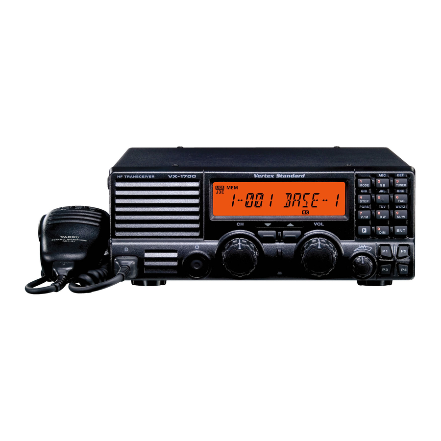
ENERAL The Vertex Standard VX-1700 is a low-cost, integrated HF External Antenna Tuner (for an end-fed random-length wire or long whip antenna), YA-30 Broadband Dipole communications transceiver designed for the Land Mobile Antenna, YA-007FG Mobile Antenna, MD-200 market. Desk Microphone, MLS-100 External Speaker, and the ALE-... -
Page 4: Front Panel Control & Switches
POWER Switch frequency (Clarifier function). This is the main on/off switch for the VX-1700. Press P2 Key: Toggles the Key Lockout feature “on” and and hold in this switch for one second to toggle the “off.”... - Page 5 Activates the “Dual Watch” feature. Selects the Scan Resume mode. None None Toggles the Display intensity between “High” and “Low.” Engages the Set (Menu) mode. None None Activetes the “Alternate” key function. Disables the “Alternate” key function. VX-1700 O Page 3...
-
Page 6: Rear Panel Connections
ANEL ONNECTIONS INPUT ( 13.8 V ) TUNER Jack This is the main DC power input jack for the VX-1700. This 8-pin mini-DIN jack is for interconnection to the optional FC-30 or FC-40 External Antenna Tuner. ANT Jack ACC Jack This PL-259 (“M”... -
Page 7: Installation
Power Connections rotator cable (if used) according to the arrestor’s instruc- The power connector for the VX-1700 must only be con- tions. nected to a DC source providing 13.8 Volts DC (±15 %), In the event of an approaching electrical storm, discon- and capable of at least 22 Amperes of current. -
Page 8: Electromagnetic Compatibility And Rf Exposure
Although there is negligible radio frequency (RF) leakage dealer, if the unit was purchased over-the-counter) so as to from the VX-1700 transceiver itself, its antenna system get instructions regarding the prompt resolution of the should be located as far away from humans and animals as damage situation. -
Page 9: Power Requirements And Basic Installation
Route the DC Make sure the POWER switch on the VX-1700 trans- cable as far away from ignition cables as possible, and cut ceiver is off, and plug the DC cable into the INPUT off any extra cable (from the battery end) to minimize volt- jack on the rear panel of the transceiver. -
Page 10: Mobile Mounting
The FC-40 should be located at or near the base of the Mobile Antenna Considerations antenna, so as to minimize losses and stray radiation. The The VX-1700 transceiver is designed for use with any short lead-in wire from the whip must be securely bonded antenna system providing a 50-Ohm resistive impedance both to the FC-40 and the antenna (whip or wire), and the at the desired operating frequency. -
Page 11: Mobile Station Grounding
Bonding the rear panel GND in some installations, to provide a direct ground connec- terminal of the VX-1700 transceiver to the vehicle or tion at the mounting location of the transceiver. Due to vessel’s ground system should clear up any such difficul- unexpected resonances which may naturally occur in any ties. -
Page 12: Base Station Installation
Other models of DC power supplies may be used with the of 13.8 V ±15%. If using a power supply other than the VX-1700, but the 13.8 V DC input voltage, 25 Ampere FP-1030A, ensure that the DC supply connector to the current capability, and DC cable polarity guidelines de- transceiver matches the VX-1700 wiring configuration. -
Page 13: Base Station Antenna Considerations
20° 20° When installing a balanced antenna such as a dipole, re- member that the VX-1700 transceiver is designed for use 10° 10° with an (unbalanced) coaxial feedline. Always use a balun or other balancing device so as to ensure proper antenna system performance. -
Page 14: Base Station Grounding
Excellent reference texts and computer software are avail- able for the design and optimization of HF antennas. Your The VX-1700 HF transceiver, like any other HF commu- dealer or installer should be able to assist you with all as- nications apparatus, requires an effective ground system pects of your antenna installation. - Page 15 VX-1700 O Page 13...
-
Page 16: Operation
[ 2 ( NB )] (Noise Blanker) key to reduce the noise level. When the noise blanker is activated, the ” icon will be illuminated. Press the [ 2 ( NB )] key “ again to disable the noise blanker. VX-1700 O Page 14... -
Page 17: Front Panel Locking
Dial, press the keypad’s [ 3 ( TUNER )] key. The “ ” icon on the LCD Display will blink, and the VX-1700 will transmit for a short time. Thereafter, the transceiver will return to the receive mode, and the “... -
Page 18: Dual Watch
[ 8 ( DW )] key again to return to the normal will happen: display. If the VX-1700 is in the “Carrier Drop” mode, the trans- ceiver will hold on memory channel “1-001” until the transmission ceases. The transceiver will continue to hold for ten seconds after the transmission ends, in case the other station decides to resume transmitting. -
Page 19: Encrypted Transmission/Reception
[ ENCR ] key on the other station’s transceiver, then revert to encrypted operation immediately by pressing the [ ENCR ] key on your transceiver. VX-1700 O Page 17... -
Page 20: Selcall/Telcall Operation
ELCALL ELCALL PERATION The VX-1700’s Selcall feature provides six calling modes: ELCALL Selcall The Selcall mode allows you to make an individual/group The Selcall mode allows you to make an individual/ call using an individual ID (Identification) assigned to each group call using the individual ID (Identification) transceiver in your group or fleet. -
Page 21: Message Call
The Message Call mode allows you to send a text mes- Receiving a Message Call sage (up to 64 characters of text) to a specific station. When the VX-1700 receives a Message Call matching your individual ID, a bell alarm will be heard, and the Preparation “... -
Page 22: Position Request Call
.” Receiving a Position Request Call Press the [ CALL ] key again to transmit the Position When the VX-1700 receives a Position Request Call Send Call. matching your individual ID, the LCD will display the received (calling station’s) ID number; your radio will... -
Page 23: Beacon Request Call
Press the [ CALL ] key again to transmit the Beacon [ TELCALL ] key while holding in the PTT switch to Request Call. send the “Hang-up” signal. If the Beacon Request call is successful, the “Answer” signal from the called station will be heard. VX-1700 O Page 21... -
Page 24: Ale Operation
Press the [ 7 ( V/M )] key, as needed, to select the Memory network. After five seconds from the initial pressing Channel mode. of the [ ALE ] key, the VX-1700 will initiate the ALE Press the [ AEL ] key momentarily to activate the ALE scanner. - Page 25 VX-1700 O Page 23...
-
Page 26: Programmable Function Pf Keys
PF K ROGRAMMABLE UNCTION The VX-1700 includes four Programmable Function (P1 CH 1 - CH 4 ~ P4) Keys. The Programmable Function button functions Press the assigned programmable key to recall the Dealer can be customized, via programming by your VERTEX... - Page 27 AUX PRS TO H Press the assigned programmable key to turn the optional accessory port “2” to “High.” AUX PRS TO L Press the assigned programmable key to turn the optional accessory port “1” to “Low.” VX-1700 O Page 25...
- Page 28 VX-1700 O Page 26...
- Page 29 VX-1700 O Page 27...
- Page 30 VX-1700 O Page 28...
- Page 31 Part 15.21: Changes or modifications to this device not expressly approved by Vertex Standard could void the user’s authorization to operate this device.
- Page 32 Copyright 2005 VERTEX STANDARD CO., LTD. All rights reserved No portion of this manual may be reproduced without the permission of VERTEX STANDARD CO., LTD. Printed in Japan. 0512I-0E...