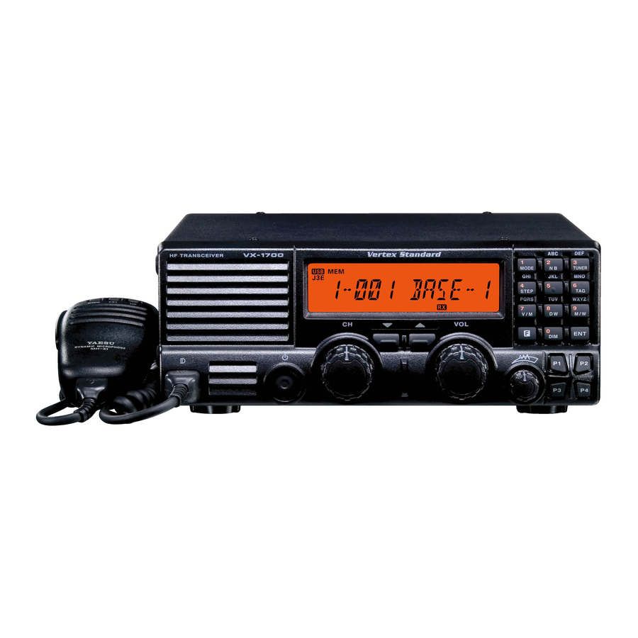
Vertex Standard VX-1700 Alignment Manual
Hide thumbs
Also See for VX-1700:
- Service manual (116 pages) ,
- Operating manual (32 pages) ,
- Reference book (10 pages)
Advertisement
Quick Links
FCC ID: K6610511070
IC ID: 511B-10511070
Alignment
VX-1700 Alignment
The VX-1700 is carefully aligned at the factory for the specified performance across the entire
operating frequency range. Realignment should therefore not be necessary except in the event of
a component failure. All component replacement and service should be performed only by an
authorized Vertex Standard representative, or the warranty policy may be void.
The following procedures cover the sometimes critical and tedious adjustments that are not
normally required once the product has left the factory. However, if damage occurs and some
parts subsequently are replaced, realignment may be required. If a sudden problem occurs during
normal operation, it is likely due to component failure; realignment should not be done until after
the faulty component has been replaced.
We recommend that servicing be performed only by authorized Vertex Standard service
technicians who are experienced with the circuitry and fully equipped for repair and alignment.
Therefore, if a fault is suspected, contact the dealer from whom the product was purchased for
instructions regarding repair. Authorized Vertex Standard service technicians realign all circuits
and make complete performance checks to ensure compliance with factory specifications after
replacing any faulty components.
Those who do undertake any of the following alignments are cautioned to proceed at their own
risk. Problems caused by unauthorized attempts at realignment are not covered by the warranty
policy. Also, Vertex Standard reserves the right to change circuits and alignment procedures in
the interest of improved performance, without notifying owners.
Under no circumstances should any alignment be attempted unless the normal function and
operation of the product are clearly understood, the cause of the malfunction has been clearly
pinpointed and any faulty components replaced, and realignment determined to be absolutely
necessary.
The following test equipment (and thorough familiarity with its correct use) is necessary for
complete realignment. Correction of problems caused by misalignment resulting from use of
improper test equipment is not covered under the warranty policy. While most steps do not
require all of the equipment listed, the interactions of some adjustments may require that more
complex adjustments be performed afterwards. Do not attempt to perform only a single step
unless it is clearly isolated electrically from all other steps. Have all test equipment ready before
beginning, and follow all of the steps in a section in the order presented.
1/7
Vertex Standard Co., Ltd.
Advertisement

Related Manuals for Vertex Standard VX-1700


Summary of Contents for Vertex Standard VX-1700
- Page 1 Alignment VX-1700 Alignment The VX-1700 is carefully aligned at the factory for the specified performance across the entire operating frequency range. Realignment should therefore not be necessary except in the event of a component failure. All component replacement and service should be performed only by an authorized Vertex Standard representative, or the warranty policy may be void.
-
Page 2: Required Test Equipment
Set up the test equipment as shown below, and apply 13.8V DC power to the transceiver. The VX-1700 must be programmed for use in the intended system before alignment is attempted. The frequency and other parameters are loaded from the file during the alignment process. -
Page 3: Pll Alignment
Key the transmitter (connect pin 6 of the MIC jack to GND), then adjust the AF Generator output level so that the RF millivoltmeter reading is approximately 0 dBm. Adjust T1008, T1009, T1010, and T1011 on the MAIN Unit in succession several times for maximum indication on the RF millivoltmeter while transmitting. Vertex Standard Co., Ltd. -
Page 4: Receiver Alignment
Remove the solder jumper which is connected between TP2020 and TP2021 on the PA Unit, then connect the “+” lead of the DC Ammeter to TP2020 and the “–” lead to TP2021. Set VR2003 on the PA Unit fully counter-clockwise. Tune the radio to 7.500 MHz, USB mode. Vertex Standard Co., Ltd. -
Page 5: Software Menu Alignment
[F] key for longer than a half second. Note that a few alignment parameters are not adjustable, and are to be left as set at the factory. Vertex Standard Co., Ltd. - Page 6 6PO-L 10 W (± 1 W) 7PO-VH 125 W (± 5 W) 7PO-H 100 W (± 5 W) 7PO-MH 50 W (± 5 W) 7PO-ML 25 W (± 1 W) 7PO-L 10 W (± 1 W) Vertex Standard Co., Ltd.
- Page 7 Press the [2128] key momentarily to recall the parameter “3_SWR3,” then press the [ENT] key. This completes the internal alignment routine. To save all settings and exit, press and hold in the [ENT] key for at least one second. Vertex Standard Co., Ltd.