Lennox MERIT ML180UHE Installation Instructions Manual
Merit series gas furnace upflow/horizontal air discharge
Hide thumbs
Also See for MERIT ML180UHE:
- Manual (33 pages) ,
- User's information manual (7 pages) ,
- Installation instructions manual (39 pages)
Table of Contents
Advertisement
E 2011 Lennox Industries Inc.
Dallas, Texas, USA
HORIZONTAL LEFT
. . . . . . . . . . . . . . . . . . . . . . . . . . . . . . . .
. . . . . . . . . . . . . . . . . . . . . . . . . . . . . .
. . . . . . . . . . . . . . . . . . . . . . . . . . . . . . .
. . . . . . . . . . . . . . . . . . . . . . . . . . . . . . . . . . . . . . . .
. . . . . . . . . . . . . . . . . . . . . . . . . . . . . . .
. . . . . . . . . . . . . . . . . . . . . . . . . . . . . . . . . . . . . . . . . .
. . . . . . . . . . . . . . . . . . . . . . . . . . . . . . . . . . . .
. . . . . . . . . . . . . . . . . . . . . . . . . . . . . . . . . . . . . . . .
06/11
*2P0611*
AIR FLOW
UPFLOW
HORIZONTAL RIGHT
Table of Contents
. . . . . . . . . . . . . . . . . . . . . . . . .
. . . . . . . . . . . . . . . . . . . . . . . .
. . . . . . . . . . .
. . . . . . . . . . . . . .
INSTALLATION
INSTRUCTIONS
ML180UHE
®
MERIT
SERIES GAS FURNACE
UPFLOW / HORIZONTAL AIR DISCHARGE
506810−01
06/2011
Supersedes 506732−01
THIS MANUAL MUST BE LEFT WITH THE
HOMEOWNER FOR FUTURE REFERENCE
This is a safety alert symbol and should never be ignored.
When you see this symbol on labels or in manuals, be alert
to the potential for personal injury or death.
Improper installation, adjustment, alteration, service
or maintenance can cause property damage, person-
al injury or loss of life. Installation and service must
be performed by a licensed professional installer (or
equivalent), service agency or the gas supplier.
As with any mechanical equipment, personal injury
can result from contact with sharp sheet metal
edges. Be careful when you handle this equipment.
2
. . . . . . . . . . . . . . . . . . . . . . . . . . . . . . . . . . . . .
. . . . . . . . . . . . . . . . . . . . . . . . . . . . . . . . . . . . . . .
3
4
. . . . . . . . . . . . . . . . . . . . . . . . . . . . . . . . . . . .
4
4
. . . . . . . . . . . . . . . . . . . . . . . . . . . . . . . . . . . .
5
5
6
. . . . . . . . . . . . . . . . . . . . . . . . . . . . . . . . . . . . . . . .
9
12
12
13
Page 1
WARNING
. . . . . . . . . . . . . . . . . . . . . . . . . . . . . . .
. . . . . . . . . . . . . . . . . . . . . . . .
. . . . . . . . . . . . . . . . . . . . . . . . . . . . . .
. . . . . . . . . . . . . . . . . . . . . . . . . .
. . . . . . . . . . . . . . . . . . . . . . . .
. . . . . . . . . . . . . . . . . . . . . . . . . . . . . . . .
. . . . . . . . . . . . . . . . . . . . . . . . . . . . . . . .
. . . . . . . . . . . . . . .
. . . . . . . . . . . . . . . . . . . . . . . . . . . . . . . . .
506810−01
*P506810-01*
Litho U.S.A.
23
25
28
29
30
30
30
31
33
35
37
37
38
39
Advertisement
Table of Contents

Related Manuals for Lennox MERIT ML180UHE


Summary of Contents for Lennox MERIT ML180UHE
-
Page 1: Table Of Contents
INSTALLATION INSTRUCTIONS E 2011 Lennox Industries Inc. Dallas, Texas, USA ML180UHE ® MERIT SERIES GAS FURNACE UPFLOW / HORIZONTAL AIR DISCHARGE 506810−01 06/2011 Supersedes 506732−01 Litho U.S.A. THIS MANUAL MUST BE LEFT WITH THE HOMEOWNER FOR FUTURE REFERENCE This is a safety alert symbol and should never be ignored. -
Page 2: Unit Dimensions
(406) 1−15/16 (49) 23−1/2 (16) 3−1/4 (597) (83) (19) (19) Bottom Return Bottom Return Air Opening Air Opening FRONT VIEW SIDE VIEW ML180UHE Model No. 045(X)E36A 14−1/2 13−3/8 4−3/4 070(X)E36B 17−1/2 16−3/8 6−1/4 090(X)E48B 090E60C 19−7/8 19−1/2 110(X)E60C 135E60D 24−1/2 23−3/8... -
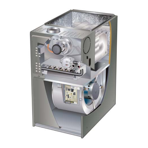
Page 3: Parts Arrangement
Parts Arrangement Make−Up Box Heat Exchanger Combustion Air Inducer Combustion Air Inducer Pressure Switch Burner Box (includes sensor, ignitor and rollout switches) Gas Valve Primary Limit Control Box (under (includes integrated control, combustion interlock switch and transformer) air inducer) Upper Access Panel Secondary Limits Blower Assembly Blower Access Panel... -
Page 4: Ml180Uhe Gas Furnace
ML180UHE Gas Furnace CAUTION The ML180UHE unit is shipped ready for installation in the As with any mechanical equipment, personal injury upflow or horizontal right position (for horizontal left posi- can result from contact with sharp sheet metal tion the combustion air pressure switch must be moved) edges. -
Page 5: Use Of Furnace As A Construction Heater
HEAT or COOL setting. See figure 2. ML180UHE units may be used for heating of buildings or structures under construction, if the following conditions Heating Unit Installed Parallel to Cooling Coil... -
Page 6: Combustion, Dilution & Ventilation Air
The requirements for providing air for combustion and ven- this section to install ML180UHE furnaces to ensure effi- tilation depend largely on whether the furnace is installed in cient and safe operation. You must consider combustion air needs and requirements for exhaust vents. - Page 7 Unconfined Space Air from Inside An unconfined space is an area such as a basement or If the confined space that houses the furnace adjoins a large equipment room with a volume greater than 50 cubic space categorized as unconfined, air can be brought in by feet (1.42 m ) per 1,000 Btu (.29 kW) per hour of the com- providing two permanent openings between the two...
- Page 8 EQUIPMENT IN CONFINED SPACE ALL AIR FROM OUTSIDE (Inlet Air from Crawlspace and Outlet Air to Ventilated Attic) CHIMNEY OR GAS VENT VENTILATION LOUVERS (Each end of attic) OUTLET WATER FURNACE HEATER INLET VENTILATION LOUVERS (For unheated crawl space) NOTE−The inlet and outlet air openings shall each have a free area of at least one square inch (645 ) per 4,000 Btu (1.17 kW) per hour of the total input rating of all equipment in the enclosure.
-
Page 9: Setting Equipment
Doing so will adversely affect the operation of the safety control devices, which could result in per- sonal injury or death. The ML180UHE gas furnace can be installed as shipped in either the upflow position or the horizontal position. Left Side... - Page 10 Return Air −− Upflow Applications Single Side Return Air Return air can be brought in through the bottom or either (with transition and filter) side of the furnace installed in an upflow application. If the furnace is installed on a platform with bottom return, make an airtight seal between the bottom of the furnace and the platform to ensure that the furnace operates properly and safely.
- Page 11 Removing the Bottom Panel Horizontal Applications Remove the two screws that secure the bottom cap to the The ML180UHE furnace can be installed in horizontal ap- furnace. Pivot the bottom cap down to release the bottom plications. Order horizontal suspension kit (51W10) from panel.
-
Page 12: Filters
TABLE 1 Horizontal Application Unit Installed on Platform Filter Size Furnace Line contact is permissible but not preferred Cabinet Width Side Return Bottom Return See the unit nameplate for clearances. A − 14−1/2" 16 X 25 X 1 (1) 14 X 25 X 1 (1) B −... -
Page 13: Venting
1 − Remove the four mounting screws (figure 15) which Venting secure the combustion air inducer / pressure switch A 4−inch diameter flue transition is factory-installed on the assembly to the orifice plate. Lift the assembly and ro- tate it 90 degrees clockwise or counterclockwise to ei- combustion air inducer outlet of all models. - Page 14 HORIZONTAL RIGHT POSITION HORIZONTAL LEFT POSITION Top Vent Discharge Top Vent Discharge Vent Pipe Vent Pipe Pressure Switch Pressure Flue Switch Transition Cover Plate Flue Transition FLOW FLOW Collector Box Make−Up Box Cover Plate Collector Box Make−Up Box D Disconnect pressure switch hose from barbed fitting on the D Gas supply piping must be brought into the unit from the bot- pressure switch assembly.
- Page 15 The lined with B1 vent or a listed insulated flexible metal vent. ML180UHE is not approved for use with horizontal venting. An exterior tile−lined chimney that is sealed and capped may be lined with a listed uninsulated flexible metal vent.
- Page 16 SEALED suitable materials, or replaced with a gas vent or chimney suitable for venting ML180UHE series units. The chimney MAX. LENGTH −− SEE NOTE 1 passageway must be checked periodically to ensure that it BELOW.
- Page 17 Common Venting Using Tile−Lined Interior Masonry Chimney and Combined Vent Connector MINIMUM LENGTH = AS SHORT AS PRACTICAL. INTERIOR TILE−LINED FOR MAXIMUM LENGTH SEE NOTE TO LEFT MASONRY CHIMNEY NOTE− Refer to provided venting tables for installations. NOTE − the chimney must be properly sized per provided venting tables or lined with listed metal lining system.
- Page 18 16 − Vent connectors serving Category I appliances shall two consecutive table size diameters over the size of not be connected to any portion of mechanical draft the draft hood outlet or flue collar outlet. systems operating under positive pressure such as 20 −...
- Page 19 TABLE 4 Capacity of Type B Double−Wall Vents with Single−Wall Metal Connectors Serving a Single Category I Appliance Vent and Connector Diameter − D (inches) Height Lateral 3 Inch 4 Inch 5 Inch 6 Inch Appliance Input Rating in Thousands of Btu Per Hour (feet) (feet) NOTE −...
- Page 20 TABLE 5 Vent Connector Capacity Type B Double−Wall Vents with Type B Double−Wall Connectors Serving Two or More Category I Appliances Vent and Connector Diameter − D (inches) Vent Connector 3 Inch 4 Inch 5 Inch 6 Inch Height Rise Appliance Input Rating in Thousands of Btu Per Hour (feet) (feet)
- Page 21 TABLE 7 Vent Connector Capacity Type B Double−Wall Vents with Single−Wall Metal Connectors Serving Two or More Category I Appliances Vent and Connector Diameter − D (inches) Height Lateral 3 Inch 4 Inch 5 Inch 6 Inch Appliance Input Rating in Thousands of Btu Per Hour (feet) (feet) NOTE −...
- Page 22 Removal of the Furnace from Common Vent 3 − Close all building doors and windows and all doors be- tween the space in which the appliances remaining In the event that an existing furnace is removed from a connected to the common venting system are located venting system commonly run with separate gas ap- and other spaces of the building.
-
Page 23: Caution
4 − The piping should be sloped 1/4 inch (6.4 mm) per 15 Gas Piping feet (4.57 m) upward toward the meter from the fur- Gas supply piping should not allow more than 0.5"W.C. drop nace. The piping must be supported at proper intervals in pressure between gas meter and unit. - Page 24 Left Side Piping MANUAL (Standard) MAIN SHUT−OFF AUTOMATIC MANUAL VALVE GAS VALVE MAIN SHUT−OFF (With 1/8 in. NPT AUTOMATIC VALVE Plugged Tap GAS VALVE (With 1/8 in. NPT Shown) Plugged Tap Shown) GROUND JOINT UNION GROUND JOINT UNION DRIP LEG Right Side Piping FIELD (Alternate)
-
Page 25: Electrical
Leak Check The unit is equipped with a field make−up box on the left hand side of the cabinet. The make−up box may be moved After gas piping is completed, carefully check all piping to the right side of the furnace to facilitate installation. If the connections (factory−... - Page 26 2 − When the ML180UHE is running in the heating mode, sure switch is closed. Any humidifier rated up to 0.5 amp the indoor blower will run on the heating speed.
- Page 27 ML180UHE Schematic Wiring Diagram and Sequence of Operation 1 − Line voltage is applied to L1 and N. the T1 low voltage transformer is energized, and line voltage is applied to B3 indoor blower. 2 − S47 rollout switch(es) must be closed in order for 24V from transformer to be output on integrated control "R" to power thermostat.
-
Page 28: Integrated Control
TYPICAL ML180UHE FIELD WIRING DIAGRAM FIGURE 33 TABLE 10 INTEGRATED CONTROL 1/4" QUICK CONNECT TERMINALS (Automatic Hot Surface Ignition System) 120HUM Humidifier 120VAC LINE 120VAC XFMR Transformer 120VAC CIRC Indoor blower 120VAC Indoor air quality accessory 120VAC NEUTRALS Common 120VAC... -
Page 29: Unit Start−Up
Turning Off Gas to Unit" and call your service techni- The gas valve on the ML180UHE unit is equipped with a cian or gas supplier. gas control switch. Use only your hand to move the switch. -
Page 30: Gas Pressure Adjustment
The maximum car- TABLE 11 bon monoxide reading should not exceed 50 ppm. GAS METER CLOCKING CHART TABLE 12 Seconds for One Revolution ML180UHE Unit Natural ML180UHE Unit L.P. 1 cu ft 2 cu ft... -
Page 31: Other Unit Adjustments
TABLE 13 Manifold Pressure Settings at all Altitudes Line Pressure in.wg. Model 0−2000 ft 2001−4500 ft. 4501−7500 ft 7501 − 10,000 ft Input Size 13.0 LP/propane 10.0 10.0 10.0 10.0 11.0 13.0 13.0 LP/propane 10.0 10.0 10.0 10.0 11.0 13.0 13.0 LP/propane 10.0... - Page 32 Watchguard control. The feature serves as an automatic re- set device for integrated control lockout caused by ignition ML180UHE units are equipped with a constant torque ECM failure. This type of lockout is usually due to low gas line motor. It has a DC motor coupled to an electronic control pressure.
-
Page 33: Blower Performance Data
BLOWER DATA ML180UH045E36A PERFORMANCE (Less Filter) External Air Volume / Watts at Various Blower Speeds Static High Medium-High Medium Medium-Low Pressure Watts Watts Watts Watts Watts in. w.g. 0.00 1380 1155 0.10 1345 1120 0.20 1320 1080 0.30 1290 1055 0.40 1265 1010... - Page 34 BLOWER DATA ML180UH090E60C PERFORMANCE (Less Filter) Air Volume / Watts at Different Blower Speeds Bottom Return Air, Side Return Air with Optional Return Single Side Return Air − Air volumes in bold require field External Air Base, Return Air from Both Sides or Return Air from fabricated transition to accommodate 20 x 25 x 1 in.
-
Page 35: Service
10 if removed). 14 −NOx units only − Replace NOx inserts. Filters All ML180UHE filters are installed external to the unit. Fil- 15 −Reinstall collector box and combustion air assembly. ters should be inspected monthly. Clean or replace the fil-... - Page 36 ML180UHE BURNER, COMBUSTION AIR INDUCER ASSEMBLY & HEAT EXCHANGER REMOVAL Gasket Flue Transition Pressure Switch Rollout Switches (−090, −110 −135 units) Heat Exchanger Rollout Switches Ignitor (−045 and −070 units) Orifice Plate Collector Box Combustion Air Inducer Sensor Retention Rings...
-
Page 37: Planned Service
Repair Parts List The following repair parts are available through independent Lennox dealers. When ordering parts, include the complete furnace model number listed on the CSA International nameplate −− Example: ML180UHE045P24A−01. All service must be performed by a licensed professional installer (or equivalent), service agency, or gas supplier. -
Page 38: Integrated Control Diagnostic Codes
Integrated Control Diagnostic Codes RED LED Diagnostic Codes / Status of Furnace Flash Code No power to control or board fault detected Board fault detected, Heartbeat Control powered − displayed during all modes of operation if no errors are detected Reverse Line Voltage Polarity Improper Earth Ground Burner failed to light, or lost flame during heat demand... -
Page 39: Troubleshooting
Troubleshooting: Heating Sequence of Operation HEATING SEQUENCE OF OPERATION ABNORMAL HEATING MODE NORMAL HEATING MODE POWER ON GAS VALVE OFF. COMBUSTION AIR INDUCER OFF. INDOOR BLOWER DELAY OFF. CONTROL SELF−CHECK OKAY? LED SLOW FLASH (RESET CONTROL BY TURNING MAIN POWER OFF.) LED FLASHES CODE 1 −... - Page 40 Troubleshooting: Heating Sequence of Operation (Continued) HEATING SEQUENCE CONTINUED NORMAL HEATING MODE ABNORMAL HEATING MODE 15-SECOND COMBUSTION AIR INDUCER PREPURGE INITIATED BY CLOSED PRESSURE SWITCH. LED FLASHES CODE 13 − LOW LINE VOLTAGE. ONCE VOLTAGE IS ABOVE IS VOLTAGE ABOVE 70 VOLTS? IGNITOR WARM-UP −−...
-
Page 41: Troubleshooting: Cooling Sequence Of Operation
Troubleshooting: Cooling Sequence of Operation COOLING SEQUENCE OF OPERATION NORMAL COOLING MODE ABNORMAL COOLING MODE POWER ON IGNITION CONTROL MAIN POWER ON. GAS VALVE OFF. COMBUSTION AIR INDUCER OFF. INDOOR BLOWER OFF WITH NORMAL DELAY. CONTROL SELF DIAGNOSTIC CHECK. SIGNAL CIRCUIT BOARD FAILURE AT LED. IS CONTROL OPERATING NORMALLY? INTERRUPT MAIN POWER TO RESET CONTROL. - Page 42 Troubleshooting: Continuous Fan Sequence of Operation CONTINUOUS FAN SEQUENCE OF OPERATION LED: SLOW FLASH RATE REMAINS UNCHANGED THROUGHOUT SEQUENCE. MANUAL FAN SELECTION MADE AT THERMOSTAT. CONTROL (G) ENERGIZES SYSTEM FAN AT FAN SPEED. EAC TERMINAL IS ENERGIZED. THERMOSTAT CALLS FOR HEAT (W). SYSTEM FAN CONTINUES FAN SPEED WITHOUT THERMOSTAT CALLS FOR COOLING.
- Page 43 Start−Up & Performance Check List UNIT SET UP (typical) Unit Model Number_______________ Serial Number___________________ SUPPLY Line Voltage upflow furnace shown Gas Supply Pressure Filter RETURN RETURN DUCT SYSTEM GAS SUPPLY SUPPLY AIR DUCT LP/Propane Gas Natural Gas Sealed Piping Connections Tight Insulated (if necessary) Leak Tested Registers Open and Unobstructed...
- Page 44 UNIT OPERATION (typical) Combustion CO SUPPLY Thermostat Gas Manifold Pressure Temperatures upflow furnace shown Filter Blower Motor Amps Duct Static RETURN RETURN COOLING MODE HEATING MODE INDOOR BLOWER AMPS______ GAS MANIFOLD PRESSURE W.C._____ TEMPERATURE DROP COMBUSTION SAMPLE CO CO PPM_______ ______ Return Duct Temperature _________ Supply Duct Temperature...