
Related Manuals for Pride Mobility Quantum 6000


Summary of Contents for Pride Mobility Quantum 6000
- Page 1 21 Healey Road • Dandenong, 3175 • Victoria, Australia • ACN# 088 609 661 • www.quantumrehab.com...
- Page 2 Performing a prohibited action can cause injury to personnel and/ or damage to equipment (black symbol with red circle and red slash). 088 609 661 Copyright © 2005 This product is manufactured by: Pride Mobility Products Corporation 182 Susquehanna Avenue Exeter, PA 18643 INFMANU3150/Rev A/September 05 www.quantumrehab.com Quantum 6000 www.quantumrehab.com...
-
Page 3: Table Of Contents
This owner’s manual is compiled from the latest specifications and product information available at the time of publication. We reserve the right to make changes as they become necessary. Any changes to our products may cause slight variations between the illustrations and explanations in this manual and the product you have purchased. Quantum 6000 www.quantumrehab.com... -
Page 4: Introduction
I N T R O D U C T I O N SAFETY WELCOME to Quantum Rehab, a division of Pride Mobility Products Corporation (Pride). The power chair you have purchased combines state-of-the-art components with safety, comfort, and styling in mind. We are confident that these design features will provide you with the conveniences you expect during your daily activities. - Page 5 T T T T T = Terminal Post Connect Red wire to T T T T T with + + + + + Connect Black wire to T T T T T with – – – – – Quantum 6000 www.quantumrehab.com...
- Page 6 3-pronged adapter to an electrical outlet having 2-pronged plug access. Failure to heed could result in personal injury and/or property damage. Prevent personal injury and equipment damage. Do not connect an extension lead to the AC/DC converter or the battery charger. www.quantumrehab.com Quantum 6000...
-
Page 7: Safety
! Check all controller connections to the power base. Make sure they are secured properly. ! Check the brakes. See VIII. “Care and Maintenance.” ! Check battery charge. See VI. “Batteries and Charging.” NOTE: If you discover a problem, contact your Quantum Rehab Specialist for assistance. Quantum 6000 www.quantumrehab.com... - Page 8 WARNING! When on any sort of an incline or decline, never place the power chair in freewheel mode while seated on it or standing next to it. Doing so may result in personal injury and/or damage to your power chair. WARNING! Never travel down an incline rearward. This may result in personal injury. www.quantumrehab.com Quantum 6000...
- Page 9 Obey all local pedestrian traffic rules. Wait until your path is clear of traffic, and then proceed with extreme caution. Quantum 6000 www.quantumrehab.com...
- Page 10 Power chairs are not designed to travel up or down stairs or escalators. Always use a lift. WARNING! Never use your power chair to negotiate steps or escalators. You may cause injury to yourself and to others and/or damage your power chair. www.quantumrehab.com Quantum 6000...
-
Page 11: Iii. "Your Power Chair
If you will be traveling with your power chair, you may find it necessary to use a lift/elevation product to aid in transporta- tion. Pride recommends that you closely review the instructions, specifications, and safety information set forth by the manufacturer of the lift/elevation product before using that product. Quantum 6000 www.quantumrehab.com... - Page 12 WARNING! If you anticipate being seated in a stationary position for an extended period of time, turn off the power. This will prevent unexpected motion from inadvertent joystick contact. This will also eliminate the possibility of unintended chair movement from electromagnetic (EM) sources. Failure to do so may result in personal injury. www.quantumrehab.com Quantum 6000...
- Page 13 WARNING! Do not operate your power chair while you are under the influence of alcohol, as this may impair your ability to operate your power chair in a safe manner. Quantum 6000 www.quantumrehab.com...
- Page 14 NOTE: For further information on EMI/RFI, go to the Resource Center on www.pridemobility.com. If unintended motion or brake release occurs, turn your power chair off as soon as it is safe to do so. Contact your Quantum Rehab Specialist to report the incident. www.quantumrehab.com Quantum 6000...
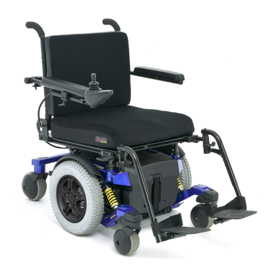
- Page 15 THE QUANTUM 6000 The Quantum 6000 has two main assemblies: the seat assembly and the power base assembly. See figure 5. Typically, the seat assembly includes the armrests, seatback, and seat base. The power base assembly includes two motor/brake assem- blies, two drive wheels, four caster wheels, two batteries, and wiring harnesses.
- Page 16 Australian testing standards. Additionally, the power chair manufacturer has successfully tested the power chair to a maximum weight capacity of 136 kg. Further information regarding the performance attributes and testing results of the power chair may be obtained by sumbitting a written request to Pride Mobility Products Australia Pty. Ltd., Attn.: Technical Services. www.quantumrehab.com...
- Page 17 SIDE NOT SHOWN) FRONT COVER MANUAL FREEWHEEL LEVER Figure 6. The Quantum 6000 Power Base ELECTRICAL COMPONENTS The electrical components consist of the controller assembly, the batteries, and the motors. The batteries, motors, and controller power module (if equipped) are located on the power base assembly. The controller is located on the seat assembly.
- Page 18 The circuit breaker will reset itself. Turn on the controller and continue normal operation. If the main circuit breaker continues to trip repeatedly, contact your Quantum Rehab Specialist. CONTROLLER POWER MODULE CONTROLLER CABLE TO MOTOR CONNECTORS QUICK RELEASE BATTERY CONNECTORS MAIN CIRCUIT BREAKER Figure 7. Quantum 6000 Electrical Components www.quantumrehab.com Quantum 6000...
- Page 19 Applying excessive force to the manual freewheel levers may result in damage to the freewheel levers, motors, and brakes. MANUAL FREEWHEEL LEVER MANUAL FREEWHEEL LEVER Figure 8. Freewheel Mode (Drive Disengaged) Figure 9. Drive Mode (Drive Engaged) Quantum 6000 www.quantumrehab.com...
- Page 20 WARNING! Prevent motor damage! Immediately release the joystick if the motors stall. Failure to release the joystick within 5 seconds of motor stall may cause the motors to overheat, resulting in damage to the motors, lack of motor performance, and/or increased motor noise. www.quantumrehab.com Quantum 6000...
-
Page 21: Assembly
ARMREST ANGLE ADJUSTMENT CONTROLLER POSITION SEAT HEIGHT/ANGLE ADJUSTMENT TYRE/TUBE REPLACEMENT FOOT PLATFORM ANGLE ADJUSTMENT FOOT PLATFORM HEIGHT/DEPTH ADJUSTMENT Figure 10. Quantum 6000 Assembly View (Synergy Seat Shown) Quantum 6000 www.quantumrehab.com... -
Page 22: Seat Installation
7. Replace the rear shroud and tighten the rear shroud fasteners. See figure 6. 8. Secure the controller cable to the armrest receiver with wire ties (contour seat only). See figure 13. Figure 12. Remote Plus Controller Routed on a Synergy Seat www.quantumrehab.com Quantum 6000... - Page 23 4. Lower the front extrusion onto the front bar of the seat place interface. 5. Flip the seat latch safety down. Figure 13. Remote Plus Controller Routed on a Contour Seat SEAT PLATE INTERFACE BRACKET ACTUATOR Figure 14. Power Seat Actuator Quantum 6000 www.quantumrehab.com...
-
Page 24: Comfort Adjustments
9. Move the trapeze bars up or down to the desired height. NOTE: Change the seat dump by raising or lowering only one set of towers (front or rear). Figure 15. Seat Height/Angle Adjustment 10. Reinstall the retaining clips. www.quantumrehab.com Quantum 6000... - Page 25 The lever is located on the right side of the seat base. To adjust the recline angle: Figure 17. Seatback/Armrest Adjustment 1. Pull up on the seatback release lever. 2. Lean forward or rearward to the desired position. 3. Release the lever. Quantum 6000 www.quantumrehab.com...
- Page 26 The quick release fastener has two states: clamped and unclamped. When the lever is open, the quick release fastener is unclamped. When the lever is closed, the quick release fastener is clamped. www.quantumrehab.com Quantum 6000...
- Page 27 See figures 12 and 13. 7. Replace the rear shround and tighten the fasteners. 8. Secure the controller cable to the armrest with wire ties Figure 22. Controller Position (Contour Seat) (contour seats only). See figure 13. Quantum 6000 www.quantumrehab.com...
- Page 28 2. Move the leg rest hanger in or out to the desired position. 3. Align the adjustment holes in the leg rest hanger with those in the side rail. 4. Reinstall the adjustment bolts to secure the leg rest hangers. Figure 25. Heavy Duty Drop-In Leg Rests www.quantumrehab.com Quantum 6000...
- Page 29 2. Tilt the foot plate to the desired position. 3. Tighten the hardware. To change foot plate angle (D): 1. Turn the setscrew clockwise to decrease the angle. 2. Turn the setscrew anticlockwise to increase the angle. SETSCREW Figure 26. Multi-Axis Foot Plate (ELR Shown) Quantum 6000 www.quantumrehab.com...
- Page 30 NOTE: The power elevating seat option is equipped with a system that reduces the speed of the power chair by one half when the seat is elevated more than 3-5 cm. Always check to be sure this system is operating properly before using your power chair. www.quantumrehab.com Quantum 6000...
-
Page 31: Batteries And Charging
BATTERIES AND CHARGING The Quantum 6000 uses two long-lasting, 12-volt, deep-cycle batteries. These batteries are sealed and maintenance free. Since they are sealed, there is no need to check the electrolyte (fluid) level. Deep-cycle batteries are designed to handle a longer and deeper discharge. - Page 32 We recommend deep-cycle batteries that are sealed and maintenance free. Both AGM and Gel-Cell are deep-cycle batteries that are similar in performance. Refer to the Specifications Table for more information regarding the batteries used with your power chair. www.quantumrehab.com Quantum 6000...
- Page 33 What about shipping? If you wish to use a freight company to ship your power chair to your final destination, repack your power chair in the original shipping container and ship the batteries in separate boxes. Quantum 6000 www.quantumrehab.com...
-
Page 34: Operation
WARNING! Unless faced with an emergency situation, do not use the on/off key to stop the chair. This will cause the power chair to stop abruptly. WARNING! Always turn the power off when you are stationary to prevent unexpected movement. www.quantumrehab.com Quantum 6000... - Page 35 “ripple up and down of lights,” turn off the controller, and allow the joystick to return to the neutral position. Then turn on the controller. NOTE: If you still get “ripple up and down of lights,” contact your Quantum Rehab Specialist. Quantum 6000 www.quantumrehab.com...
- Page 36 For every degree above 50° C/122° F, the voltage is reduced by 5 volts. This reduces your power chair’s speed and allows the electrical components to cool down. When the temperature returns to a safe level, your power chair resumes its normal speed. www.quantumrehab.com Quantum 6000...
-
Page 37: Remote Plus Error Codes
Unplug charger. Check connections. Right Motor Wiring Fault Check right motor wiring. Right Motor Disconnected Check right motor wiring. Left Motor Wiring Fault Check left motor wiring. Left Motor Disconnected Check left motor wiring. Low Battery Voltage Check batteries/battery wiring. Quantum 6000 www.quantumrehab.com... - Page 38 WARNING! If your power chair begins to move in an unexpected manner, immediately release the joystick. Unless the joystick is damaged, this action should stop your power chair. Figure 30. Microdrive Controller with Joystick Interface Module www.quantumrehab.com Quantum 6000...
- Page 39 NOTE: When a toggle switch is set to “J/S,” the joystick has control of a particular function. When the toggle switch is set to “Local,” control of this function is disabled at the joystick. Figure 31. Microdrive Display Pad Quantum 6000 www.quantumrehab.com...
- Page 40 Error codes are displayed as a number of flashing lights. For instance, if the first light is flashing rapidly, the battery voltage is nearly depleted. The following table identifies the individual error codes, probable causes, and possible solutions. If you get one of these error codes, contact your Quantum Rehab Specialist. www.quantumrehab.com Quantum 6000...
- Page 41 Unplug charger. Check connections. Right Motor Wiring Fault Check right motor wiring. Right Motor Disconnected Check right motor wiring. Left Motor Wiring Fault Check left motor wiring. Left Motor Disconnected Check left motor wiring. Low Battery Voltage Check batteries/battery wiring. Quantum 6000 www.quantumrehab.com...
-
Page 42: Care And Maintenance
M A I N T E N A N C E CARE AND MAINTENANCE Your Quantum 6000 is a sophisticated power chair. Like any motorised vehicle, it requires routine maintenance checks. You can perform some of these checks, but others require assistance from your Quantum Rehab Specialist. Preventive maintenance is very important. - Page 43 ! Check the caster forks for damage or fluttering which indicates that they may need to be adjusted or have the bearings replaced. See your Quantum Rehab Specialist for repair. ! Keep your power chair clean and free of foreign material, such as mud, dirt, hair, food, drink, etc. Quantum 6000 www.quantumrehab.com...
- Page 44 10. Reinstall the five (5) lug nuts onto the wheel hub and tighten. 11. Inflate the pneumatic tyre to 2.4 bar (35 psi). 12. Remove the power chair from the blocks. FRONT WHEEL HALF NUTS Figure 32. Quantum 6000 Drive Wheel www.quantumrehab.com Quantum 6000...
- Page 45 8. Connect the battery harness to the rear battery according to the battery wiring diagram. See figure 33. 9. Install new batteries. 10. Reinstall the front cover and foot platform. 11. Charge the batteries. See VI. “Batteries and Charging.” Quantum 6000 www.quantumrehab.com...
- Page 46 A N D M A I N T E N A N C E BATTERY WIRING DIAGRAM LABEL FRONT COVER REAR SHROUD REAR SHROUD FASTENER (OPPOSITE SIDE NOT SHOWN) RELEASE HANDLES FRONT BATTERY REAR BATTERY Figure 33. Battery Installation www.quantumrehab.com Quantum 6000...
- Page 47 Disconnect both batteries before load testing and follow the directions that come with the load tester. If either one of the batteries fails the load test, replace both of them. If your power chair still does not power up, contact your Quantum Rehab Specialist. Quantum 6000 www.quantumrehab.com...
- Page 48 Replacement Units The availability of replacement units is subject to the discretion of the provider, not the manufacturer. For more information regarding replacement units, contact your authorised Pride Provider. www.quantumrehab.com Quantum 6000...
- Page 49 N O T E S Quantum 6000 www.quantumrehab.com...
- Page 50 N O T E S www.quantumrehab.com Quantum 6000...
- Page 51 We have Q u a l i t y C o n t r o l - M o d e l 1 400 Quality Control - Quantum 6000 thoroughly inspected your Quantum 6000. The following...