Table of Contents
Advertisement
Advertisement
Table of Contents

Related Manuals for MSI MS-9A19


Summary of Contents for MSI MS-9A19
- Page 1 MS-9A19 Fanless Box PC...
-
Page 2: Copyright Notice
Alterna- tively, please try the following help resources for further guidance. ◙ Visit the MSI website for FAQ, technical guide, BIOS updates, driver updates and other information via http://www.msi.com/index. php?func=service ◙... -
Page 3: Safety Instructions
MS-9A19 Safety Instructions ■ Always read the safety instructions carefully. ■ Keep this User’s Manual for future reference. ■ Keep this equipment away from humidity. ■ Lay this equipment on a reliable flat surface before setting it up. ■ The openings on the enclosure are for air convection hence protects the equipment from overheating. -
Page 4: Fcc-B Radio Frequency Interference Statement
VOIR LA NOTICE D’INSTALLATION AVANT DE RACCORDER AU RESEAU. Micro-Star International MS-9A19 This device complies with Part 15 of the FCC Rules. Operation is subject to the following two conditions: this device may not cause harmful interference, and this device must accept any interference received, including interference that may cause undesired operation. -
Page 5: Weee (Waste Electrical And Electronic Equipment) Statement
MSI will comply with the product take back requirements at the end of life of MSI-branded products that are sold into the EU. You can return these products to local collection points. - Page 6 MSI će poštovati zahtev o preuzimanju ovakvih proizvoda kojima je istekao vek trajanja, koji imaju MSI oznaku i koji su prodati u EU. Ove proizvode možete vratiti na lokalnim mestima za pri- kupljanje.
- Page 7 MSI si adeguerà a tale Direttiva ritirando tutti i prodotti marchiati MSI che sono stati venduti all’interno dell’Unione Europea alla fine del loro ciclo di vita. È possibile portare i prodotti nel...
-
Page 8: Table Of Contents
▍ PREFACE ▍ TABLE OF CONTENTS Copyright Notice ����������������������������������������������������������������������������������������� ii Trademarks ������������������������������������������������������������������������������������������������� ii Revision History ����������������������������������������������������������������������������������������� ii Technical Support �������������������������������������������������������������������������������������� ii Safety Instructions ������������������������������������������������������������������������������������ iii FCC-B Radio Frequency Interference Statement ����������������������������������� iv WEEE (Waste Electrical and Electronic Equipment) Statement ������������ v Chapter 1 Overview ���������������������������������������������������������������������������������... -
Page 9: Chapter 1 Overview
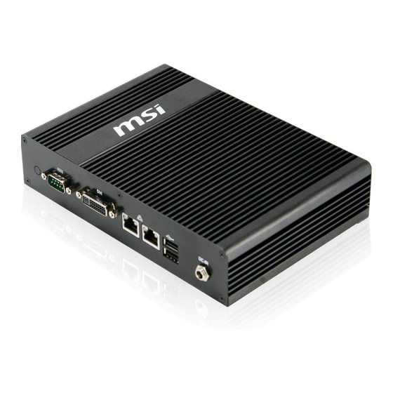
Overview Thank you for choosing the MS-9A19, an excellent industrial computer system from MSI. The MS-9A19 eliminates the noise and the risk of fan’s failure by wide heatsink as fanless solution. Further- more, it supports VESA wall-mount interface for vari-... -
Page 10: Packing Contents
▍ ▍ OVERVIEW OVERVIEW acking ontents Power Adapter MS-9A19 System Power Cord HDD Screw Set SATA Cable Driver/Utility Disk Bracket User’s Manual ■ The above illustrations are for reference only and your packing contents may slightly vary depending on the model you purchased. -
Page 11: System Overview
MS-9A19 MS-9A19 ystem verview External View Internal View... - Page 12 ▍ ▍ OVERVIEW OVERVIEW SO-DIMM Slot Mini PCI-E Slot Serial Port Cable USB Bracket SATA Ports Front View Rear View...
-
Page 13: Serial Port
MS-9A19 MS-9A19 Serial Port The serial port is a 16550A high speed communications port that sends/ receives 16 bytes FIFOs. You can attach a serial mouse or other serial devices directly to the connector. Power Button/LED Press the power button to turn the system on or off. The power LED glows when the system is turned on and goes off when the system is shut down. -
Page 14: System Specifications
▍ ▍ OVERVIEW OVERVIEW ystem Pecifications Processor ■ Intel Atom N270 low power processor ■ 533/ 400 MHz Chipset ■ North Bridge: Intel 945GSE chipset ■ South Bridge: Intel ICH7M chipset Memory ■ 1 DDR2 533/667 SO-DIMM slot (200 pins / 1.8V) ■... -
Page 15: Power Supply
MS-9A19 MS-9A19 Power Supply ■ 36 watt power adapter with active PFC ■ Input: 100-240V~, 50-60Hz, 1.2A ■ Output: 12V Dimension ■ 210mm x 100mm x 50mm Regulatory Compliance ■ FCC Class B, CE, C-Tick, BSMI, VCCI, RoHS compliance Environmental ■... -
Page 16: Mainboard Layout
▍ OVERVIEW ainboard ayout MS-9856 v1�X Mainboard... -
Page 17: Chapter 2 System Assembly
Chapter 2 System Assembly This chapter provides you with the information on system assembly procedures. While doing the instal- lation, be careful in holding the components and follow the installation procedures. For some components, if you install in the wrong orientation, the components will not work properly. -
Page 18: Installation Tools
▍ SYStEM ASSEMblY nstaLLation ooLs A Phillips (crosshead) screwdriver and a flathead screw- driver, can be used to do most of the installation. Choose one with a magnetic head would be better. Pliers, can be used as an auxiliary tool to connect some connectors or cables. -
Page 19: Removing The Chassis Cover
MS-9A19 emoving the hassis over Step 1: Locate and remove the screws on the rear panel. Step 2: Remove the 9 screws on the top. -
Page 20: System Assembly
▍ SYStEM ASSEMblY Step 3: Push the chassis cover gently outwards. Step 4: The system fan has been preinstalled in the system. Disconnect the fan power connector and put the chassis cover aside for later use. -
Page 21: Installing Memory
MS-9A19 nstaLLing emory Step 1: Locate the SO-DIMM slot. Step 2: Align the notch on the DIMM with the key on the slot and insert the DIMM into the slot at a 45-degree angle. Step 3: Push the DIMM gently downwards until the slot levers click and lock the DIMM in place. -
Page 22: Installing The Wireless Lan Card
▍ SYStEM ASSEMblY Lan c nstaLLing the ireLess Step 1: Break open the antenna hole on the rear panel. Step 2: Insert the antenna connector into the hole and tighten it with a hex nut. Step 3: Connect the external WLAN antenna. - Page 23 MS-9A19 Step 4: Locate the mini PCI-E slot and re- move the LAN card screw preinstalled on the mainboard. Step 5: Insert the wireless LAN card into the mini PCI-E slot at a 45-degree angle. Step 6: Push the card gently down and fasten it with screw.
-
Page 24: Installing The Hard Disk Drive
▍ SYStEM ASSEMblY nstaLLing the rive Step 1: Insert the HDD into the HDD bracket with screw holes aligned. Step 2: Place the rubber washers on the screw holes of the HDD bracket. Step 3: Tighten the four screws to fix the HDD to the bracket. Important Please make sure the HDD is properly and completely fixed to the bracket. - Page 25 MS-9A19 Step 4 Connect the SATA signal & power cable to the HDD. Step 5: Locate the SATA ports and the HDD power connector on the mainboard. Connect the SATA power cable to the HDD power connector. Step 6: Connect the SATA signal cable to the...
-
Page 26: Replacing The Chassis Cover
▍ SYStEM ASSEMblY ePLacing the hassis over Step 1: Connect the fan power connector. Step 2: Place the chassis cover onto the chassis and push it inwards until it fits into the chassis. 2-10... - Page 27 MS-9A19 Step 3: Fasten the 9 screws on the top of the chassis. Step 4: Tighten the 9 screws on the rear panel. 2-11...
-
Page 28: Connecting The Brackets
▍ SYStEM ASSEMblY onnecting the rackets Step 1: Remove the four screws on the top of the chassis (as indicated by yellow circles). Step 2: Fasten the brackets to the chassis with the chassis screws. 2-12... -
Page 29: Mainboard Jumpers
MS-9A19 ainboard umPers COM Port Power Jumper: JCOMP1 These jumpers specify the operation voltage of the onboard serial ports. VCC5 +12V VCC5 +12V JCOMP1 Clear CMOS Jumper: JBAT1 There is a CMOS RAM onboard that has a power supply from an external battery to keep the data of system configuration. -
Page 31: Chapter 3 Bios Setup
Chapter 3 BIOS Setup This chapter provides information on the BIOS Setup program and allows you to configure the system for optimum use. You may need to run the Setup program when: ■ An error message appears on the screen during the system booting up, and requests you to run SETUP. -
Page 32: Entering Setup
▍ BIOS SETUP ntering etuP Power on the computer and the system will start POST (Power On Self Test) pro- cess. When the message below appears on the screen, press <DEL> key to enter Setup. Press DEL to enter SETUP If the message disappears before you respond and you still wish to enter Setup, restart the system by turning it OFF and On or pressing the RESET button. -
Page 33: Control Keys
MS-9A19 Control Keys <↑> Move to the previous item <↓> Move to the next item <←> Move to the item in the left hand <→> Move to the item in the right hand <Enter> Select the item <Esc> Jumps to the Exit menu or returns to the main menu from a sub- menu <+/PU>... -
Page 34: The Menu Bar
▍ BIOS SETUP ▶ Main Use this menu for basic system configurations, such as time, date etc. ▶ Advanced Use this menu to setup the items of special enhanced features. ▶ Boot Use this menu to specify the priority of boot devices. ▶... -
Page 35: Main
MS-9A19 ▶ System Time This setting allows you to set the system time. The time format is <Hour> <Minute> <Second>. ▶ System Date This setting allows you to set the system date. The date format is <Day>, <Month> <Date> <Year>. - Page 36 ▍ BIOS SETUP [Block Any selection except Disabled determines the (Multi-Sector number of sectors transferred per block Transfer)] [PIO Mode] Indicates the type of PIO (Programmed Input/Output) [DMA Mode] Indicates the type of Ultra DMA [S.M.A.R.T.] This allows you to activate the S.M.A.R.T. (Self-Monitoring Analysis &...
-
Page 37: Advanced
MS-9A19 dvanced ▶ CPU Configuration... - Page 38 ▍ BIOS SETUP ▶ Max CPUID Value Limit The Max CPUID Value Limit BIOS feature allows you to circumvent prob- lems with older operating systems that do not support the Intel Pentium 4 processor with Hyper-Threading Technology. When enabled, the processor will limit the maximum CPUID input value to 03h when queried, even if the processor supports a higher CPUID input value.
- Page 39 MS-9A19 ▶ PCI/PCIE Device Configuration ▶ USB Functions This setting specifies the operation mode of the onboard USB control- ler. ▶ USB 2�0 Controller This setting enables/disables the onboard USB controller. ▶ Audio Controller This setting enables/disables the onboard audio controller.
- Page 40 ▍ BIOS SETUP ▶ Super IO Configuration ▶ Serial Port 1/2/3/4/5/6 Address, Serial Port 3/4/5 IRQ Select an address and a corresponding interrupt for the specified serial ports. ▶ Serial Port 3/4/5 Mode These settings specify the operation mode of the specified serial ports. ▶...
- Page 41 MS-9A19 ▶ Hardware Health Configuration These items display the current status of all monitored hardware devices/ components such as voltages, temperatures and all fans’ speeds. 3-11...
- Page 42 ▍ BIOS SETUP ▶ GPIO Configuration ▶ GP 60/ 61/ 62/ 63/ 64/ 65/ 66/ 67 Data These settings configure special GPIO data. 3-12...
-
Page 43: Boot
MS-9A19 ▶ 1st/2nd/3rd Boot Device The items allow you to set the sequence of boot devices where BIOS at- tempts to load the disk operating system. ▶ Try Other Boot Devices Setting the option to [Enabled] allows the system to try to boot from other device if the system fails to boot from the 1st/2nd/3rd boot device. -
Page 44: Security
▍ BIOS SETUP ecurity ▶ Supervisor Password / Change Supervisor Password Supervisor Password controls access to the BIOS Setup utility. These set- tings allow you to set or change the supervisor password. ▶ User Password / Change User Password User Password controls access to the system at boot. These settings allow you to set or change the user password. -
Page 45: Chipset
MS-9A19 hiPset ▶ Internal Graphics Mode Select The field specifies the size of system memory allocated for video memory. ▶ DVMT Mode Select Intel’s Dynamic Video Memory Technology (DVMT) allows the system to dy- namically allocate memory resources according to the demands of the sys- tem at any point in time. - Page 46 ▍ BIOS SETUP ▶ Boot Display Device Use the field to select the type of device you want to use as the display(s) of the system. ▶ Force LVDS Inactive This setting determines whether to force the LVDS inactive or not. 3-16...
-
Page 47: Power
MS-9A19 ower ▶ ACPI Aware O/S This setting enables/disables ACPI (Advanced Configuration and Power In- terface) support for Operating System. Set to [No] if your OS doesn’t support ACPI and set to [Yes] if ACPI is supported. ▶ Suspend Mode This item specifies the power saving modes for ACPI function. - Page 48 ▍ BIOS SETUP ▶ USB Device Wakeup From S3/S4 This setting allows the activity of the USB device to wake up the system from the S3/S4 sleep state. ▶ Resume On LAN This field specifies whether the system will be awakened from power saving modes when activity or input signal of onboard LAN is detected.
-
Page 49: Exit
MS-9A19 ▶ Save Changes and Exit Save changes to CMOS and exit the Setup Utility. ▶ Discard Changes and Exit Abandon all changes and exit the Setup Utility. ▶ Discard Changes Abandon all changes and continue with the Setup Utility.