Advertisement
Quick Links
SERVICE MANUAL
Ver 1.1 2003. 05
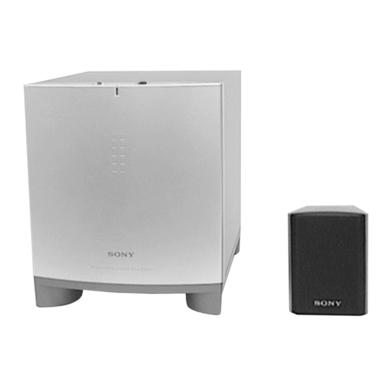
• This set is the Speaker section in HT-K170/
K215.
• The SA-VE215 system consists of one unit
of SA-WMS215 and five units of SS-MS215.
SS-MS215 Front, center and rear speakers
Speaker system
Speaker units
Enclosure type
Rated impedance
Power handling
capacity
(Maximum input
power)
Sensitivity level
Frequency range
Dimensions (w/h/d)
Mass
Sony Corporation
9-929-500-12
2003E16-1
Home Audio Company
© 2003.05
Published by Sony Engineering Corporation
Photo: SA-WMS215
SPECIFICATIONS
Full range, magnetically
shielded
5 cm cone type
Bass reflex
8 ohms
60 watts
84 dB (1W, 1m)
150 Hz - 20,000 Hz
Approx. 76 × 100 × 86 mm
including front grille
Approx. 425 g
SA-VE215/WMS215/
SS-MS215
Australian Model
Photo: SS-MS215
SA-WMS215 Subwoofer
System
Active subwoofer,
Speaker system
magnetically shielded
Speaker unit
Woofer : 16 cm cone type
Enclosure type
Acoustically Loaded Bass Reflex
Continuous RMS
50 W
power output
(8 ohms, 20 - 250 Hz)
Reproduction
32 Hz - 250 Hz
frequency range
High frequency
250 Hz
cut-off frequency
Input
LINE IN (input pin jack)
General
Power requirements
220 - 230 V AC, 50/60 Hz
Power consumptions
45 W
Approx. 240 × 285 × 355 mm
Dimensions (w/h/d)
including front panel
Mass
Approx. 8 kg
Design and specifications are subject to change without
notice
SPEAKER SYSTEM
AEP Model
UK Model
E Model
Chinese Model
Advertisement

Related Manuals for Sony SA-VE215


Summary of Contents for Sony SA-VE215
- Page 1 E Model Australian Model Chinese Model • This set is the Speaker section in HT-K170/ K215. • The SA-VE215 system consists of one unit of SA-WMS215 and five units of SS-MS215. Photo: SA-WMS215 Photo: SS-MS215 SPECIFICATIONS SS-MS215 Front, center and rear speakers...
-
Page 2: Safety-Related Component Warning
COMPONENTS IDENTIFIED BY MARK 0 OR DOTTED LINE WITH MARK 0 ON THE SCHEMATIC DIAGRAMS AND IN THE PARTS LIST ARE CRITICAL TO SAFE OPERATION. REPLACE THESE COMPONENTS WITH SONY PARTS WHOSE PART NUMBERS APPEAR AS SHOWN IN THIS MANUAL OR IN SUPPLEMENTS PUBLISHED BY SONY. - Page 3 SECTION 1 DIAGRAMS 1-1. NOTE FOR PRINTED WIRING BOARDS AND SCHEMATIC DIAGRAMS • IC Block Diagram IC302 uPC1237HA Note on Printed Wiring Board: Note on Schematic Diagram: • X : parts extracted from the component side. • All capacitors are in µF unless otherwise noted. pF: µµF •...
- Page 4 SA-VE215/WMS215/SS-MS215 • See page 3 for IC block diagram. 1-2. SCHEMATIC DIAGRAM (SA-WMS215) The components identified by mark 0 or dotted line with mark 0 are critical for safety. Replace only with part number specified.
- Page 5 SA-VE215/WMS215/SS-MS215 1-3. PRINTED WIRING BOARD (SA-WMS215) • See page 3 for Circuit Boards Location. There are a few cases that the part printed on this diagram isn’t mounted in this model. • Semiconductor Location Ref. No. Location D301 D302 D303...
-
Page 6: Section 2 Exploded Views
SECTION 2 EXPLODED VIEWS NOTE: 2-2. SA-WMS215 (2) • -XX, -X mean standardized parts, so they may • Accessories and packing materials are given in The components identified by mark 0 or have some differences from the original one. the last of this parts list. dotted line with mark 0 are critical for safety. - Page 7 Ver 1.1 2003.05 2-3. SS-MS215 not supplied Ref. No. Part No. Description Remarks Ref. No. Part No. Description Remarks A-4412-322-A PANEL ASSY, FRONT 1-529-763-11 SPEAKER (5cm) A-4412-277-A CABINET ASSY 4-986-971-11 SCREW (3.5) 1-694-516-11 TERMINAL, SPEAKER 3-703-564-81 SCREW (3.5X12), TAPPING A-4461-007-A OVERALL ASSY...
-
Page 8: Electrical Parts List
SECTION 3 CONTROL MAIN ELECTRICAL PARTS LIST NOTE: • Due to standardization, replacements in the • RESISTORS When indicating parts by reference number, parts list may be different from the parts All resistors are in ohms. please include the board name. specified in the diagrams or the components METAL: metal-film resistor The components identified by mark 0 or... - Page 9 MAIN POWER IC POWER SUPPLY POWER SWITCH Ref. No. Part No. Description Remarks Ref. No. Part No. Description Remarks < RESISTOR > 1-678-474-11 POWER SUPPLY BOARD ******************** R101 1-249-417-11 CARBON 1/4W F R102 1-249-441-11 CARBON 100K 1/4W 1-533-233-11 HOLDER, FUSE R103 1-249-441-11 CARBON 100K...
-
Page 10: Revision History
SA-VE215/WMS215/SS-MS215 REVISION HISTORY Clicking the version allows you to jump to the revised page. Also, clicking the version at the upper right on the revised page allows you to jump to the next revised page. Ver. Date Description of Revision 2000.