Table of Contents
Advertisement
SERVICE MANUAL
Ver 1.0 2000.2
• The SA-VE230 system consists of one unit
of SA-WMS230, one unit SS-CN230 and
four units of SS-V230.
AUDIO POWER SPECIFICATIONS
POWER OUTPUT AND TOTAL
HARMONIC DISTORTION :
with 8
loads both channels driven, from 20 - 150 Hz; rated
50 W per channel minimum RMS power, with no more than
0.8% total harmonic distortion from 250 mW to rated output.
Ss-V230 F
ront and rear speakers
Speaker system
Speaker units
Enclosure type
Rated impedance
Power handling capacity
Maximum input power: 100 W
Sensitivity level
Frequency range
Dimensions (w/h/d)
Mass
Ss-Cn230 Center speaker
Speaker system
Speaker units
Enclosure type
Rated impedance
Power handling capacity
Maximum input power: 120 W
Sensitivity level
Frequency range
Dimensions (w/h/d)
Mass
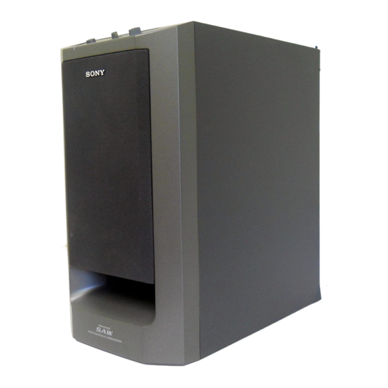
Photo: SA-WMS230
SPECIFICATIONS
Full range, magnetically shielded
9 cm (
5
5
2
3
/
in.), cone type
8
Bass reflex
8
86 dB (1W, 1m)
90 Hz - 20,000 Hz
Approx. 70
151
126 mm
7
(2
/
6 5 in.), including front
8
grille
Approx. 550 g (1 lb 3 oz) each
Full range
2, magnetically
shielded
9 cm (
5
2
3
5
/
in.), cone type
8
Bass reflex
8
88 dB (1W, 1m)
90 Hz - 20,000 Hz
Approx. 301
70
126 mm
(11
7
/
2
7
/
5 in.), including front
8
8
grille
Approx. 1.1 kg
(2 lb 7 oz)
SA-VE230/WMS230/
SS-CN230/V230
Canadian Model
Photo: SS-CN230
Photo: SS-V230
SA-WMS230 Subwoofer
System
Speaker system
Active subwoofer, magnetically
shielded
Speaker unit
Woofer : 16 cm (6
cone type
Enclosure type
Advanded SAW type
Continuous RMS power output
(8 , 20 - 150 Hz, 0.8 % THD)
50 W
Reproduction frequency range
28 Hz - 200 Hz
High frequency cut-off frequency
200 Hz
Input
LINE IN (input pin jack)
General
Power requirements
120 V AC, 60 Hz
Power consumptions
45 W
Dimensions (w/h/d)
Approx. 205
1
1
(8
/
15
/
15
8
4
front grille
Mass
Approx. 10.5 kg
(23 lb 2 oz)
Supplied accessories
Foot pads (20)
Audio connecting cords (2 phono to 2 phono) (3)
Monaural connecting cord (1 phono to 1 phono) (1)
9
Speaker connecting cords, 10 m (32 ft
1
2
Speaker connecting cords, 2.5 m (8 ft
Design and specifications are subject to change
without notice
MICRO SATELLITE SYSTEM
US Model
3
/
in.),
8
385 385 mm
1
/
in.), including
4
3
/
in.) (2)
4
/
in.) (3)
2
Advertisement
Table of Contents

Related Manuals for Sony SS-V230


Summary of Contents for Sony SS-V230
- Page 1 SS-CN230/V230 SERVICE MANUAL US Model Canadian Model Ver 1.0 2000.2 • The SA-VE230 system consists of one unit of SA-WMS230, one unit SS-CN230 and four units of SS-V230. Photo: SS-CN230 Photo: SA-WMS230 Photo: SS-V230 SPECIFICATIONS AUDIO POWER SPECIFICATIONS SA-WMS230 Subwoofer...
- Page 2 Leakage current can be measured by any one of three methods. CRITIQUES POUR LA SÉCURITÉ DE FONCTIONNEMENT. NE REMPLACER CES COMPOSANTS QUE PAR DES PIÈSES SONY A commercial leakage tester, such as the Simpson 229 or RCA DONT LES NUMÉROS SONT DONNÉS DANS CE MANUEL OU WT-540A.
- Page 3 SECTION 1 DIAGRAMS 1-1. NOTE FOR PRINTED WIRING BOARDS AND SCHEMATIC DIAGRAMS • IC Block Diagrams IC302 uPC1237H Note on Printed Wiring Board: Note on Schematic Diagram: • X : parts extracted from the component side. • All capacitors are in µF unless otherwise noted. pF: µµF •...
- Page 4 SA-VE230/WMS230/SS-CN230/V230 • See page 3 for IC block diagrams. 1-2. SCHEMATIC DIAGRAM (SA-WMS230) The components identified by Les composants identifiés par mark 0 or dotted line with mark une marque 0 sont critiques 0 are critical for safety. pour la sécurité. Replace only with part number Ne les remplacer que par une specified.
- Page 5 SA-VE230/WMS230/SS-CN230/V230 1-3. PRINTED WIRING BOARD (SA-WMS230) • See page 3 for Circuit Boards Location. • Semiconductor Location CONTROL BOARD Ref. No. Location D101 F-11 D102 F-11 D103 G-11 POWER BOARD D104 G-11 D301 D302 LED BOARD D303 D304 D501 D502 (11) D503 (POWER)
- Page 6 SECTION 2 EXPLODED VIEWS NOTE: 2-2. SA-WMS230 (2) • -XX, -X mean standardized parts, so they may • The mechanical parts with no reference number The components identified by mark 0 or have some differences from the original one. in the exploded views are not supplied. dotted line with mark 0 are critical for safety.
- Page 7 2-3. SS-CN230 not supplied @ @ @ Ref. No. Part No. Description Remarks Ref. No. Part No. Description Remarks X-4952-574-1 PANEL ASSY, FRONT 1-694-516-11 TERMINAL, SPEAKER 3-703-564-31 SCREW (3.5) 1-529-578-11 SPEAKER (5X9cm) X-4952-575-1 CABINET ASSY, SPEAKER 1-529-578-11 SPEAKER (5X9cm)
- Page 8 2-4. SS-V230 not supplied @ @ @ Ref. No. Part No. Description Remarks Ref. No. Part No. Description Remarks X-4952-572-1 PANEL ASSY, FRONT 1-694-516-11 TERMINAL, SPEAKER 3-703-564-31 SCREW (3.5) 1-529-577-11 SPEAKER (5X9cm) X-4952-573-1 CABINET ASSY, SPEAKER...
- Page 9 SECTION 3 CONTROL MAIN ELECTRICAL PARTS LIST NOTE: • Due to standardization, replacements in the • RESISTORS • SEMICONDUCTORS parts list may be different from the parts All resistors are in ohms. In each case, u: µ, for example: specified in the diagrams or the components METAL: metal-film resistor uA...: µA...
- Page 10 MAIN POWER Ref. No. Part No. Description Remarks Ref. No. Part No. Description Remarks D302 8-719-991-33 DIODE 1SS133T-77 R131 1-249-441-11 CARBON 100K 1/4W D303 8-719-991-33 DIODE 1SS133T-77 R132 1-249-429-11 CARBON 1/4W D501 8-719-025-03 DIODE RBA-402 R133 1-249-429-11 CARBON 1/4W D503 8-719-933-84 DIODE UZL-15M R301 1-249-427-11 CARBON...
-
Page 11: Power Switch
POWER SWITCH Ref. No. Part No. Description Remarks Ref. No. Part No. Description Remarks 1-676-716-11 POWER SWITCH BOARD ACCESSORIES & PACKING MATERIALS ******************** ******************************* < CONNECTOR > 1-558-271-11 CORD, CONNECTION 1-769-329-21 CORD, CONNECTION (PIN-PIN) 1-564-321-00 PIN, CONNECTOR 2P 1-769-433-11 CORD, SPEAKER 4-226-572-11 MANUAL, INSTRUCTION (ENGLISH)(US) <... - Page 12 SA-VE230/WMS230/SS-CN230/V230 Sony Corporation 9-929-074-11 2000B1620-1D Home Audio Division Company Printed in Japan © 2000.2 Published by Quality Assurance Dept.