Panasonic WR-DA7 Application Manual
Hide thumbs
Also See for WR-DA7:
- User manual (369 pages) ,
- Service manual (86 pages) ,
- Application manual (63 pages)

Related Manuals for Panasonic WR-DA7


Summary of Contents for Panasonic WR-DA7
-
Page 1: Application Guide
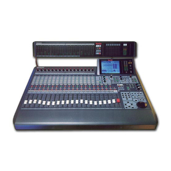
Application Guide Audio Mixer WR-DA7 The meter bridge shown in photo is one of the optional accessories. - Page 2 Limit of Liability/Disclaimer of Warranty: The author, Audio Video Systems Division of Matsushita Communication Industrial Co., Ltd has used its best efforts in preparing this book. However, Audio/Video Systems Division of Matsushita Communication Industrial Co., Ltd makes no representation or warranties with respect to the accuracy or completeness of the contents of this book and hereby specifically disclaims any implied warranties or merchantability or fitness for any particular purpose and shall in no event be liable for any loss of profit or any other commer- cial damage, including but not limited to special, incidental, consequential, or other damages.
-
Page 3: Table Of Contents
Table of Contents 1. Introduction 2. Notes for connections with peripheral equipment 2.1 Wordclock 2.2 Installing and using option cards with the WR-DA7 2.3 ADAT, BRC 2.4 DA-98, 88, 38 2.5 DAT (with AES/EBU or S/PDIF I/O) 2.6 Digital timepiece 3. -
Page 4: Introduction
1. Introduction This Application Guide supplies examples for interfacing the WR-DA7 with commonly used periperal recording equipment. This guide’s diagrams provide the necessary connections and the methods for establishing proper system operation. 3.1 System configuration 3.9 System configuration Power AES/EBU... -
Page 5: Notes For Connections With Peripheral Equipment
2 track A input [2TR IN A] and Slot 1,2 or 3. For example: it is possible to select the WR-AESS card as the wordclock source of the WR-DA7. The DA7 can be synchronized with the digital audio signals being input on Channels 1/2 of the WR-AESS card. - Page 6 The WR-DA7 allows ON/OFF of the 75-Ohm terminator on the wordclock input. ON: Is selected when the WR-DA7 is used as a wordclock master or as a slave at the end of the wordclock connections (terminated at 75 Ohm). (A clock output synchronized with DA7 is generated at the word clock’s output.)
-
Page 7: Adat, Brc
MASTER: When used with the tandem master unit. SLAVE: When used with the tandem slave unit. To connect two WR-DA7 mixers in Tandem, install a WR-TNDM card in Slot 3 of each mixer (with the mixers powered OFF). Select MASTER/SLAVE on the front panel of each WR-TNDM card. - Page 8 The ADATs must be powered-up before the BRC. The BRC should be turned on last. Wordclock If the ADAT is being used as the wordclock master set the ADAT wordclock to INT. The WR-DA7 functions as an ADAT SLAVE. The WR-DA7 wordclock settings can be set by pressing the D-I/O switch to display the INPUT SET window of the D-I/O setup section.
-
Page 9: Da-98
To use a DA-88 as the wordclock master, connect a 75 ohm BNC to BNC cable from the WORD SYNC OUT terminal of the DA-88 to the WCK IN terminal of the WR-DA7. Then press the D-I/O switch of the WR-DA7 several times in order to display the INPUT SET screen of the D-I/O window. - Page 10 When the WR-DA7 is the wordclock master, the BNC cable should be connected from the WORD CLOCK OUT terminal of the WR-DA7 to the WORD SYNC IN terminal of the DA-98 or 38. Select WORD by pressing the CLOCK switch on the front panel of the DA-98 or 38.
-
Page 11: Dat (With Aes/Ebu Or S/Pdif I/O)
DTP . When the DTP is used as the MIDI interface with MMC from the WR-DA7 for the ADAT or the DA- 98, 88, or 38 connected through the DTP and the SYNC cable, the following operation takes place:... -
Page 12: Wr-Da7 System Applications
WR-DA7 and firmly fasten them to the mixer using the supplied screws. Connect the WR-ADAT card of the WR-DA7 to the DIGITAL IN/OUT terminal of the ADAT using an optical cable and press the DIGITAL IN switch on the front panel of the ADAT to select the digital input mode. - Page 13 System configuration-1 Power AES/EBU Effector CR MONITOR MONITOR SEND A IN WCK MASTER ADAT DIGITAL WR-ADAT Optical Cable SLOT 1 (17-24ch) TRACK8 ANALOG OUT SMPTE IN (RCA) WR-SMPT (XLR) WR-DA7 INPUT 1-16 Sampler Keyboard...
-
Page 14: Example Of Systems For Adat (3Units) And Brc
BRC, and having the ADAT controlled by MMC from the WR-DA7. Method of connection With the mixer powered OFF insert the option card WR-ADAT in Slot 1, 2, 3 of the WR-DA7 and fas- ten them to the securely using the 4 screws. - Page 15 DA7 and the MMC’s MIDI channel of the BRC. On the BRC, secure a display of 11: MIDI Device screen by MIDI/UTIL setting. Set the value of ‘MIDI channel set for the WR-DA7 - 1.’ Otherwise, set- ting should be made at ‘ALL.’...
-
Page 16: System Configuration
Sync Cable DIGITAL WR-ADAT SYNC OUT Optical Cable SLOT 1 ADAT (17-24ch) Sync Cable DIGITAL WR-ADAT SYNC OUT SLOT 2 Optical Cable ADAT (25-32ch) Sync Cable DIGITAL WR-ADAT WR-ADAT SLOT 3 Optical Cable (9-16ch) ADAT WR-DA7 INPUT 1-8 Sampler Keyboard... -
Page 17: Example Of Systems With Two Wr-Da7 In Tandem With 4 Adats And Brc
Set the switch on the front of WR-TNDM card to MASTER for the WR-DA7 that is to being used as a master unit. Set switch on the card to SLAVE of the WR-DA7 being used as a slave unit. - Page 18 SETUP screen. For the TANDEM SLAVE unit, set the SEND/RECEIVE of the various MIDI messages to ‘THRU.’ For MTC reception on the WR-DA7, set MTC PORT to ‘MIDI’ in the MIDI SETUP screen of the TANDEM Master unit. To obtain the MTC timecode display on the LCD screen set the TIME BASE to ‘MTC’ in the AUTOMATION EXECUTE screen of the Automation SETUP SECTION.
- Page 19 To accomplish MMC operation, the MIDI channel of the WR-DA7 and the MIDI channel of the BRC must be set to the same channel. On the BRC, obtain a display of 11: MIDI Device screen by MIDI/UTIL setting. Set the value of ‘MIDI channel set for the WR-DA7 - 1.’ Otherwise, the settings should be made to ‘ALL.’...
- Page 20 Sync DIGITAL Cable WORD CLOCK WR-ADAT OUT (75 =OFF) SYNC OUT SLOT 2 Optical Cable To PC (25-32ch) ADAT (MASTER) WR-TANDM WR-DA7 SLOT 3 INPUT 1-16 (MASTER) Sampler Sync Keyboard Cable MIDI MIDI WR-TANDM WORD CLOCK (SLAVE) SLOT 3 IN (75 =ON)
-
Page 21: Example Of Systems With 3 Da-88S
Machine Control) from the WR-DA7. Method of connection With the DA7 powered OFF insert the WR-TDIF (option card) in Slot 1, 2, 3 of the WR-DA7 and firmly fasten them to the console with the supplied screws. Using the dip switches on the WR-TDIF card make the proper setting for the DA-88 (SW1, 2 to OFF, OFF respectively). - Page 22 No playback is produced when ALL INPUT is ON; For playback, ALL INPUT should be set to OFF. For MMC control of the DA-88 from the WR-DA7, set the MODE dip switch #2 to 0 (OFF) on the rear panel of the SY-88 in order to make the MIDI port effective.
- Page 23 MIDI MIDI (BNC) with SY-88 TDIF-1 TDIF-1 SYNC OUT WR-TDIF PW-88DL SLOT 1 (17-24ch) PW-88S DA-88 TDIF-1 TDIF-1 WR-TDIF PW-88DL SYNC OUT SLOT 2 (25-32ch) DA-88 PW-88S TDIF-1 TDIF-1 WR-TDIF PW-88DL Terminator SLOT 3 (9-16ch) INPUT 1-8 WR-DA7 Sampler Keyboard...
-
Page 24: Example Of Systems For Wr-Da7 Tandem Connections With Da-98(1Unit) And Da-38(3Units)
Set the dip switches on the WR-TDIF card of the DA-98 and 38 (both SW1, 2 at ON, OFF). Set the rear switch of the WR-TNDM card to MASTER for the WR-DA7 that is to be used as a master unit and set the slave WR-DA7 to SLAVE. - Page 25 WR-DA7 setting To use the WR-DA7 as a slave unit, set the SOURCE SELECT to ‘WCK IN’ in the INPUT SET window of the D-I/O Setup Section on the MASTER unit. (For wordclock synchronization using the DA98’s connection slot, set the SOURCE SELECT to ‘SLOT1’...
- Page 26 TDIF-1 TDIF-1 WORD CLOCK WR-TDIF SYNC OUT OUT (75 =OFF) PW-88DL SLOT 2 To PC (25-32ch) DA-38 WR-TANDM (MASTER) SLOT 3 WR-DA7 INPUT 1-16 (MASTER) Sampler PW-88S Keyboard MIDI MIDI WORD CLOCK IN (75 =ON) WR-TANDM To PC (SLAVE) SLOT 3...
-
Page 27: Example Of Systems For Analog 16-Track Recorder(1Unit)
Set the WR-DA7 to the wordclock master. In the INPUT SET screen of D-I/O of the WR-DA7, set SOURCE SELECT to ‘INT 48k’ or ‘INT 44.1k.’ To display the SMPTE timecode being received at the SMPTE IN, set the TIME BASE to ‘SMPTE’ in... - Page 28 System configuration -6 Power AES/EBU Effector CR MONITOR MONITOR A IN SEND WCK MASTER 16Track Analog Multitrack Recorder WR-ADDA SLOT 1 (17-24ch) WR-ADDA SLOT 2 (25-32ch) Track16 Analog Out SMPTE IN WR-SMPT (XLR) INPUT 1-16 WR-DA7 Sampler Keyboard...
-
Page 29: Example Of Systems For Digtal Video Recorder (1Unit)
SMPTE timecode from the Digital Video Recorder for it’s editing and automation operations. Method of connection Insert the option card of WR-AESS (Slot 1) and the WR-SMPTE (option card) in the WR-DA7 and fasten them to the console using the supplied screws. Select the switches on the WR-AESS card to AES/EBU. - Page 30 CR MONITOR WCK MASTER House Video Sync MONITOR A IN SEND V-SYNC IN(BNC) WR-SMPT SMPTE IN(XLR) SW-OFF (BNC) SMPTE OUT SLOT 1 (XLR) (17-24ch) DIGITAL DIGITAL IN/OUT WR-AESS (D-sub (XLR) SW=AES/EBU 25pin) Digital Video Recorder INPUT 1-16 WR-DA7 Sampler Keyboard...
-
Page 31: Example Of Systems For Vtr (1Unit), Adat (1Unit), And Brc
Method of connection Insert the option card WR-ADAT in Slot 1 of the WR-DA7 and firmly fasten it to the Da7 with the supplied screws. Connect the WR-ADAT card from the WR-DA7 to the DIGITAL IN/OUT of the ADAT using an optical cable and press the DIGITAL IN switch on the ADAT’s front panel to select the digital input mode. - Page 32 To accomplish MMC operation, there must be coincidence of the MIDI channel between MMC output from the WR-DA7 and MMC received on the BRC. On the BRC, set the display to 11: MIDI Device screen by MIDI/UTIL setting. Set the value of ‘MIDI channel set for the WR-DA7 - 1.’...
- Page 33 WORD CLOCK IN (48kHz OUT) (75 =ON) SMPTE IN SMPTE OUT (Phone) WR-SMPT REMOTE OUT SMPTE IN (XLR) TO ADAT WCK MASTER Sync Cable DIGITAL WR-ADAT WR-ADAT SYNC IN Optical Cable SLOT 1 ADAT (17-24ch) WR-DA7 INPUT 1-16 Sampler Keyboard...
-
Page 34: Example Of Systems For Vtr (1Unit) And Da-98 (1Unit)
Method of connection With the DA7 powed off, insert the option card WR-TDIF in Slot 1 of the WR-DA7 and firmly fasten it to the mixer with the supplied screws. Make the setting for the DA-88 with the dip switches on the WR-TDIF card (SW1, 2 to OFF, respectively). - Page 35 To enable the DA-98 to receive digital input from the TDIF-1, press the DIGITAL IN button on the front panel. When the timecode output of the video recorder is generated after being converted to MTC, the MODE dip switch 6 on the SY-88 rear side is set to OFF. (If this switch is set to ON, the timecode recorded on the tape is converted into MTC and the resultant output is generated.) Use the tape where the recorded timecode has the same frame rate as that of the SMPTE timecode output generated from the video.
- Page 36 House Video Sync Monitor VIDEO Power Effector SMPTE Timecode MONITOR SEND REC OUT MIDI IN MIDI OUT MIDI MIDI TIMECODE TDIF-1 TDIF-1 WR-TDIF PW-88DL VIDEO IN DA-98 WORD CLOCK IN WORD SYNC OUT (75 =ON) (BNC) (BNC) INPUT 1-16 WR-DA7 Sampler Keyboard...
- Page 37 aV0499-0 DA7ApplicationGuide Printed in Japan Matsushita Communication Industrial Co., Ltd. 1999...