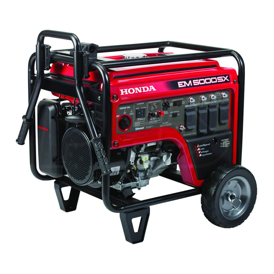
Honda EM5000SX Owner's Manual
Honda portable generator owner's manual
Hide thumbs
Also See for EM5000SX:
- Owner's manual (124 pages) ,
- Information (28 pages) ,
- Owner's manual (71 pages)
Table of Contents
Advertisement
Quick Links
Advertisement
Table of Contents

Related Manuals for Honda EM5000SX


Summary of Contents for Honda EM5000SX
- Page 3 Thank you for purchasing a Honda generator. We want to help you get the best results from your new generator and to operate it safely. This manual contains the information on how to do that; please read it carefully. This owner’s manual describes EM5000SXKl Honda Generator.
-
Page 4: Table Of Contents
CONTENTS SAFETY ... Safety Label Locations ... Safety Information COMPONENT IDENTIFICATION CONTROLS ... Engine Switch Recoil Starter ... Fuel Valve ... Choke Rod ... Circuit Breaker ... Grond Terminal ... Oil Alert System ... System ... Auto-throttle Volt Meter ... Pilot Lamp ... - Page 5 MAINTENANCE Maintenance Schedule ... Tool Kit ... Engine Oil Change ... Air Cleaner Service ... Fuel Sediment Cup ... Spark Plug ... Spark Arrester Maintenance TRANSPORTING/STORAGE TROUBLESHOOTING WIRING DIAGRAM..SPECIFICATIONS INSTALLATION OF OPTIONAL PARTS ... WARRANTY SERVICE..INDEX ...
-
Page 6: Safety
SAFETY SAFETY LABEL LOCATION These labels warn you of potential hazards that can cause serious injury. Read them carefully. If a label comes off or becomes hard to read, contact your Honda Generator dealer for a replacement. WARNING DO NOT !JSE INDOORS. EXHAUST GAS CONTAINS POISONOUS CARBON MONOXIDE. - Page 7 . .--- CAUTION n BE SUR~fb?ILL _.---- -.- CRANKCASE WITH RECOMMENDED BEFORE USING~ ~‘EXPLANATI~~U. FOR DETAILEO -___ -_ ____ __ _-..I SEE THE OWNER’S MANUAL ITOR CO.. LTD. -.--- ~-- ~-~ 11 VOLTAGE FREQUENCY RATED OUTPUT MAX. OUTPUT PHAsE MADE IN JAPAN @i CURRENT 120/24OV 11 VOLTAGE...
-
Page 8: Safety Information
SAFETY INFORMATION Honda generators are designed to give safe and dependable operated according to instructions. manual before operating your generator. You can help prevent accidents by being familiar with your generator’s controls, and by observing safe operating procedures Operator Responsibility Know how to stop the generator Understand the use of all generator controls, output receptacles,... - Page 9 Fire and Burn Hazards The exhaust system gets hot enough to ignite some materials. Keep the generator at least 1 meter (3 feet) away from buildings and other equipment during operation. Do not enclose the generator in any structure. Keep flammable materials away from the generator. The muffler becomes very hot during operation and remains hot for a while after stopping the engine.
-
Page 10: Component Identification
COMPONENT IDENTIFICATION VOLT METER ENGINE SWITCH CHOKE ROD RCUlT BREAKER UN0 TERMINAL ENGINE SERIAL NUMBER... - Page 11 FUEL METER FUEL TANK CAP -SPARK PLUG SERIAL NUMBER MUFFLER Record the engine and frame serial numbers for your future reference. Refer to these serial numbers when ordering parts, and when making technical or warranty inquiries (see page 47) Frame serial number: Engine serial number:...
-
Page 12: Controls
CONTROLS Engine Switch To start and stop the engine. Key position: OFF: START: ENGINE Return the key to the ON position once the engine has started. Do not use the starter for more than 5 seconds at a time. If the engine fails to start, release the switch and wait 10 seconds before operating the starter again. -
Page 13: Fuel Valve
Fuel Valve The fuel valve is located between the fuel tank and carburetor. When the valve lever is in the ON position, fuel is allowed to flow from the fuel tank to the carburetor. Be sure to return the lever to OFF after stopping the engine. Choke Rod The choke is used to provide proper starting mixture when the engine is cold. -
Page 14: Circuit Breaker
Circuit Breaker The circuit breaker will automatically a significant overload of the generator at the receptacle. If the circuit breaker is switched OFF automatically, and does not exceed the rated load capacity of the circuit before switching the circuit breaker ON again. The circuit breaker may be used to switch the generator power on or off. -
Page 15: Auto-Throttle System
Auto-throttle System The auto-throttle system automatically reduces engine speed when all loads are turned off or disconnected. reconnected, the engine returns to the rated speed. AUTO: Recommended further reduce noise levels when no load is applied to the generator. OFF: The auto-throttle system does not operate. -
Page 16: Volt Meter
Pilot Lamp The pilot lamp is illuminated when the generator is operating normally. It indicates that the generator is producing electrical power at the 120 or 120/ 240 volt receptacles. If the pilot light is illuminated, the volt meter should be displaying 120 or 240 volts depending on the position of the voltage selector switch. -
Page 17: Dc Terminals
DC Terminals The DC terminals may ONLY be used for charging 12 volt automotive type batteries. The terminals are colored red to identify the positive (+) terminal and black to identify the negative (-) terminal. The battery must be connected to the generator DC terminals with the proper polarity (battery positive to generator red terminal and battery negative to the generator black terminal). -
Page 18: Generator Use
GENERATOR USE Connections to a Building’s Connections for standby power to a building’s electrical system must be made by a qualified electrician. The connection must isolate the generator power from utility power, and must comply with all applicable electrical codes. Improper connections can ailbw electrical current from the generator to backfeed into the utility lines. -
Page 19: Ac Applications
AC Applications Before connecting an appliance or power cord to the generator: Make sure that it is in good working order. Faulty appliances or power cords can create a potential for electrical shock. If an appliance begins to operate abnormally, becomes sluggish or stops suddenly, turn it off immediately. -
Page 20: Ac Operation
AC Operation 1. Start the engine (refer to page 27). 2. Turn the voltage selector switch to either position. With the voltage selector switch in the “120/240V”position, 120V and 120/24OV receptacles simultaneously. 120/24OV receptacle, receptacle, then select the “12OV ONLY” position. 3. -
Page 21: Ac Receptacle Selection
AC Receptacle Selection The generator has two separate main power producing circuits. These two circuits supply equal power to different receptacles voltage selector switch is in the 120/240 V position. When two or more receptacles are used; prevent overloading by dividing the load between the two power circuits. -
Page 22: Dc Operation
DC Operation The DC terminals may ONLY be used for charging 12 volt automotive-type batteries . Connecting the battery cables: 1. Before connecting charging cables to a battery that is installed in avehicle, disconnect the vehicle’s grounded battery cable. The battery gives off explosive flames and cigarettes away. -
Page 23: Disconnecting The Battery Cables
Disconnecting the battery cables: 1. Stop the engine, 2. Disconnect the negative (-) battery cable from the generator negative (-) terminal. 3. Disconnect the other end of the negative (-) battery cablefrom the battery negative (-) terminal. 4. Disconnect the positive (+) battery cable from the generator positive (+) terminal. -
Page 24: Auto-Throttle System
Auto-throttle system With the switch in the AUTO position, engine speed is automatically when ALL loads are turned OFF or disconnected. turned ON or reconnected, position, the auto-throttle The auto-throttle system will not respond to electrical loads of less than 1 ampere. -
Page 25: High Altitude Operation
High Altitude Operation At high altitude, the standard carburetor air-fuel mixture will be excessively rich. Performance will decrease, and fuel consumption will increase. High altitude performance can be improved by installing a smaller diameter main fuel jet in the carburetor and readjusting the pilot screw. If you always operate the engine at altitudes higher than 6,000 feet above sea level, have an authorized Honda generator dealer perform this carburetor modification. -
Page 26: Preoperation Check
PRE-OPERATION CHECK Engine oil 1 NOTICE 1 Engine oil is a major factor affecting engine performance and setvice life. Non-detergent the engine and are not recommended. Check the oil level BEFORE EACH USE with the generator surface with the engine stopped. Honda 4-stroke equivalent... -
Page 27: Fuel Recommendation
Fuel Recommendation 1. Check the fuel level gauge. 2. Refill the tank if the fuel level is low. Do not fill above the shoulder of the fuel strainer. Gasoline is extremely flammable and is explosive under certain conditions. Refuel in a well-ventilated smoke or allow flames or sparks in the area where the engine is refueled or where gasoline is stored. - Page 28 Occasionally you may hear light “spark knock’ or “pinging” (metallic rapping noise) while operating under heavy loads. This is no cause for concern. If spark knock or pinging occurs at a steady engine speed, under normal load, change brands of gasoline. If spark knock or pinging persists, see an authorized Honda generator dealer.
-
Page 29: Starting The Engine
1. Make sure that the AC circuit breaker is in the OFF position. The generator may be hard to start if a load is connected. 2. Turn the fuel valve to the ON position. 3. The automatic choke will be closed if the engine is cold. If you want to operate the choke manually, position. -
Page 30: Stopping The Engine
STOPPING THE ENGINE In an emergency: 1. To stop the engine in an emergency, turn the engine switch to the OFF position. In normal use: 1. Turn the AC circuit breaker to the OFF position. Disconnect DC battery charging cables. 2. -
Page 31: Maintenance
Periodic maintenance and adjustment is necessary to keep the generator in good operating condition. Perform the service and inspection at the intervals shown in the Maintenance schedule below. Exhaust Shut off the engine before performing any maintenance. if the engine must be run, make sure the area is well ventilated. -
Page 32: Tool Kit
Tool kit The tools supplied with the generator will help you to perform the owner maintenance procedures listed on the following page. Always keep this tool kit with the generator. 10 x 12 mm WRENCH SCREW DRIVER DRIVER HANDLE PLUG WRENCH HANDLE TOOL BAG... -
Page 33: Engine Oil Change
Engine oil change Drain the oil while the engine is warm to assure rapid and complete draining. 1. Remove the drain plug and sealing washer, oil filler cap, and drain the oil. 2. Install the drain plug and sealing washer. Tighten the plug securely. 3. -
Page 34: Air Cleaner Service
Air cleaner service A dirty air cleaner will restrict air flow to the carburetor. To prevent carburetor malfunction, service the air cleaner regularly. Service more frequently when operating the generator in extremely dusty areas. Using gasoline or flammable solvent to clean the filter element can cause a fire or explosion. -
Page 35: Fuel Sediment Cup
Fuel Sediment Cup Cleaning The sediment cup prevents dirt or water which may be in the fuel tank from entering the carburetor. sediment cup should be cleaned. 1. Turn the fuel valve to the OFF position. Remove the sediment cup, O-ring, and filter. -
Page 36: Spark Plug
Spark Plug Service Recommended spark plugs: To ensure proper engine operation, the spark plug must be properly gapped and free of deposits. If the engine has been running, the muffler will be very hot. Be careful not to touch the muffler. 1. -
Page 37: Spark Arrester Maintenance
7. Check that the spark plug washer is in good condition, and thread the spark plug in by hand to prevent cross-threading. 8. After the spark plug is seated, tighten with a spark plug wrench to compress the washer. If installing a new spark plug, tighten l/2 turn after the spark plug seats to compress the washer. -
Page 38: Transporting/Storage
When transporting the generator, turn the engine switch OFF and keep the generator level to prevent fuel spillage. Fuel vapor or spilled fuel may ignite. Contact with a hot engine or exhaust system can cause serious burns or fires. Let the engine cool before transporting storing the generator. - Page 39 1. Drain the carburetor by loosening the drain screw. Drain the gasoline into a suitable container. Gasoline is extremely conditions Perform this task in a well ventilated area with the engine stopped. Do not smoke or allow flames or sparks in the area during this procedure.
-
Page 40: Troubleshooting
TROUBLESHOOTING When the engine will not start: Is there enough oil in Is there a spark from the spark plug? Besure there is no spilled fuel around the spark plug. Spilled fuel may ignite. If the engine If the engine still still does not start, take... - Page 41 No electricity at the AC receptacles: Turn the ACcircuitbreaker ON.) Check the electrical NO DEFECTS appliance or equipment for any defects.
-
Page 42: Wiring Diagram
ING DIAGRAM... -
Page 43: Specifications
17.0 e (4.5 US gal, 3.74 Imp gal) BPR5ES (NGK), WlGEPR-U Only for charging 12 V automotive batteries. Maximum charging output = 8.3 A are subject to change without notice. SPECIFICATIONS EM5000SX 80 kg (176.4 lb) GX340Kl 8.0 : 1 3,600 r.p.m. Forced air... -
Page 44: Installation Of Optional Parts
INSTALLATION Remote Control Kit 1. Install the relay box on the right side of the generator. 2. Remove the blind 8-P connector from the back of the control box and connect the relay box connector instead. 3. Connect the remote control cable to the remote control and relay box. REMOTE CONTROL CABL NOTE:... - Page 45 Remote Control Box ENGINE STARTER SWITCH BUlTON PILOT LAMP Starting the engine with remote control 1. Turn the fuel valve to the ON position. 2. Turn the auto-throttle switch to the OFF position. 3. Turn off the engine switch at the generator and remove the key. 4.
- Page 46 5. Turn the engine switch at the remote control box to the ON position. 6. Press the starter button until the pilot lamp comes on. Stopping the engine 1. Turn the engine switch at the remote control box to the OFF position. 2.
- Page 47 4-Wheel Kit Installation 1. Install the four wheels on the axle shaft. 2. Install the axle assembly on the generator using four bolts and nuts. Inside WHEEL STOPPER NOTE: Install the shaft with wheel stopper facing engine side.
- Page 48 Battery Tray Kit 1. Install the battery guard on the frame. Set the battery tray on the battery guard and tighten the bolts. 2. Route the starter cable under the tank and connect it to the starter solenoid. 3. Connect the ground cable to the generator rear housing. 4.
- Page 49 STARTER STARTER SOLE,NOID BAlTERY NOTE: Use a battery rated at 12V-18-35AH nr mnrP BATTERY GUARD BRACKET BAl-rERY TRAY GUARD PLATE...
-
Page 50: Warranty Service
WARRANTY SERVICE Owner satisfaction Your satisfaction and goodwill are important to your dealer and to us. All Honda warranty details are explained in the Distributor’s Limited Warranty. Normally, any problems concerning’ the product will be handled by your dealer’s service department. been handled to your satisfaction, we suggest you take the following action: Discuss your problem with a member of dealership management. -
Page 51: Index
IDENTIFICATION COMPONENT CONTROLS Auto-throttle System ... Choke Rod ... Circuit Breaker ... DC Circuit Protector ... DC Terminals Engine Switch ... Fuel Valve ... Grond Terminal ... Oil Alert System ... Pilot Lamp ... Recoil Starter ... Volt Meter ... Voltage Selector Switch (Dual Voltage System) ... -
Page 52: Wiring Diagram
INDEX PREOPERATION Engine Oil ................24 Fuel Recommendation SAFETY . - Page 53 MEMO...
- Page 54 MEMO...