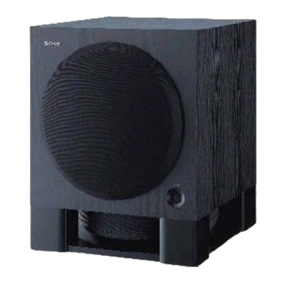
Sony SA-WX700 Service Manual
Hide thumbs
Also See for SA-WX700:
- User manual ,
- Specifications (2 pages) ,
- Instruction & operation manual (2 pages)
Advertisement
Table of Contents
SERVICE MANUAL
Ver 1.2 2004.05
AUDIO POWER SPECIFICATIONS
For the U.S.A. model
POWER OUTPUT AND TOTAL HARMONIC
DISTORTION:
With 3 ohm loads, from 20 – 200 Hz; rated 200 watts, minimum RMS
power, with no more than 0.8 % total harmonic distortion from 250
milliwatts to rated output.
System
Type
Active Subwoofer, magnetically shielded (closed cabinet)
Speaker units
Woofer : 25 cm dia. (10 in.), cone type x 2
Continuous RMS output
North American model
(3 ohms/100Hz, 0.8%) : 250 W
European model (DIN 3 ohms/100Hz, 0.7%) : 250 W
RMS output
Other models (3 ohms/100Hz, 10%) : 350 W
Reproduction frequency range
20 Hz - 200 Hz
High frequency cut-off frequency
50 Hz - 200 Hz
Phase selector
NORMAL, REVERSE
Sony Corporation
9-877-137-03
Home Audio Company
2004E02-1
Published by Sony Engineering Corporation
© 2004.05
SA-WX700
SPECIFICATIONS
Inputs
Input jacks
LINE IN: input pin jack
SPEAKER IN: input terminals
Output jacks
LINE OUT: output pin jack
SPEAKER OUT: output terminals
General
Power requirements
US, Canadian models : 120 V AC, 60 Hz
AEP model : 230 - 240 V AC, 50/60 Hz
UK model : 230 - 240 V AC, 50/60 Hz
Power consumption
70 W
less than 0.5 W (Standby mode)
Dimensions
Approx. 390 x 490 x 480 mm
(15
3
/
x 19
3
/
x 19 in.) (w/h/d)
8
8
Mass
24 kg (52lb 15oz)
Supplied accessories
Audio connecting cord
(1 phono plug - 1 phono plug) (1)
Speaker cords (2)
Design and specifications are subject to change without notice.
US Model
Canadian Model
AEP Model
UK Model
ACTIVE SUBWOOFER
Advertisement
Table of Contents

Related Manuals for Sony SA-WX700


Summary of Contents for Sony SA-WX700
-
Page 1: Specifications
(1 phono plug - 1 phono plug) (1) Phase selector Speaker cords (2) NORMAL, REVERSE Design and specifications are subject to change without notice. ACTIVE SUBWOOFER Sony Corporation 9-877-137-03 Home Audio Company 2004E02-1 Published by Sony Engineering Corporation © 2004.05... -
Page 2: Table Of Contents
SONY PARTS WHOSE PART NUMBERS APPEAR AS FONCTIONNEMENT. NE REMPLACER CES COMPOSANTS SHOWN IN THIS MANUAL OR IN SUPPLEMENTS PUB- QUE PAR DES PIÈCES SONY DONT LES NUMÉROS SONT LISHED BY SONY. DONNÉS DANS CE MANUEL OU DANS LES SUPPLÉMENTS... -
Page 3: General
SA-WX700 SECTION 1 SECTION 2 Ver 1.1 GENERAL DIAGRAMS This section is extracted from instruction manual. THIS NOTE IS COMMON FOR SCHEMATIC DIAGRAMS. • Location of controls (In addition to this, the necessary note is printed in each block.) For Schematic Diagrams. -
Page 4: Schematic Diagram -Filter Section
SA-WX700 Ver 1.1 2-2. SCHEMATIC DIAGRAM –FILTER SECTION –... -
Page 5: Printed Wiring Board - Filter Section
SA-WX700 Ver 1.1 2-3. Printed Wiring Board – FILTER SECTION – • See page 3 for Circuit Boards Location. CONTROL BOARD FILTER BOARD RELAY RELAY C242 BOARD BOARD C221 C215 C223 (SIDE A) (SIDE B) VR301 R216 VR302 C241 LEVE... -
Page 6: Schematic Diagram -Power Section
SA-WX700 Ver 1.1 2-4. SCHEMATIC DIAGRAM –POWER SECTION –... -
Page 7: Printed Wiring Board - Power Section (Side A)
SA-WX700 Ver 1.1 2-5. Printed Wiring Board – POWER SECTION (SIDE A) – • See page 3 for Circuit Boards Location. POWER BOARD (SIDE A) R855 L805 1-688-700- (11) -
Page 8: Printed Wiring Board - Power Section (Side B)
SA-WX700 Ver 1.1 2-6. Printed Wiring Board – POWER SECTION (SIDE B) – • See page 3 for Circuit Boards Location. POWER BOARD (SIDE B) L803 AEP,UK AC IN R802 CN802 L801 L802 CN801 POWER • Semiconductor C833 G D S... -
Page 9: Exploded Views
SA-WX700 SECTION 3 Ver 1.2 EXPLODED VIEWS NOTE : The components identified by • The mechanical parts with no reference number in the • -XX, -X mean standardized parts, so they mark 0 or dotted line with mark exploded views are not supplied. -
Page 10: Rear Panel Section
SA-WX700 Ver 1.1 3-2. REAR PANEL SECTION not supplied not supplied not supplied not supplied not supplied supplied not supplied The components identified by mark 0 or dotted line with mark 0 are critical for safety. F801 Replace only with part number not supplied specified. -
Page 11: Electrical Parts List
SA-WX700 SECTION 4 CONNECTOR ELECTRICAL PARTS LIST CONTROL FILTER NOTE : When indicating parts by reference num- • Items marked “ * ”are not stocked since they • Due to standardization, replacements in the ber, please include the board. are seldom required for routine service. Some... - Page 12 SA-WX700 Ver 1.1 FILTER INPUT POWER Ref. No. Part No. Description Remark Ref. No. Part No. Description Remark R218 1-249-427-11 CARBON 6.8K 1/4W R110 1-249-421-11 CARBON 2.2K 1/4W R219 1-249-431-11 CARBON 1/4W R220 1-249-435-11 CARBON 1/4W R111 1-249-417-11 CARBON 1/4W...
- Page 13 SA-WX700 Ver 1.1 POWER Ref. No. Part No. Description Remark Ref. No. Part No. Description Remark C828 1-100-166-11 ELECT(BLOCK) 4700uF D816 8-719-984-80 DIODE 1SR139-200 C829 1-164-159-11 CERAMIC 0.1uF D817 8-719-984-80 DIODE 1SR139-200 D818 8-719-991-33 DIODE 1SS133T-77 C830 1-104-661-91 ELECT 330uF...
- Page 14 SA-WX700 Ver 1.1 POWER POWER SWITCH RELAY Ref. No. Part No. Description Remark Ref. No. Part No. Description Remark Q811 8-729-016-42 TRANSISTOR KTC3199GR-TP R852 1-249-429-11 CARBON 1/4W Q812 8-729-029-86 TRANSISTOR DTC124ESA R853 1-249-435-11 CARBON 1/4W Q813 8-729-029-86 TRANSISTOR DTC124ESA R854 1-215-893-81 METAL OXIDE 1.5K...
- Page 15 SA-WX700 MEMO...
- Page 16 SA-WX700 US Model Canadian Model SERVICE MANUAL AEP Model UK Model Ver 1.1 2004.05 SUPPLEMENT-1 File this supplement with the service manual. Subject: Change of Power Board (SPM-04042) 9-877-137-81...
- Page 17 SA-WX700 Printed wiring board of new type is described this supplement-1. Refer to original service manual (9-877-137-[][]) previously issued for the other information. (Schematic diagram, parts list, etc.) When performing service and inspection, check the suffix of the part number of the power boards.
- Page 18 SA-WX700 –12 Printed Wiring Board – POWER SECTION (SIDE A) – (Refer to Service Manual page 6 for Schematic Diagram) POWER BOARD (SIDE A) 1-688-700- (12)
- Page 19 SA-WX700 –12 Printed Wiring Board – POWER SECTION (SIDE B) – (Refer to Service Manual page 6 for Schematic Diagram) POWER BOARD (SIDE B) L803 AEP,UK AC IN R802 CN802 L801 L802 CN801 • Semiconductor POWER Location C833 G D S...
- Page 20 SA-WX700 REVISION HISTORY Clicking the version allows you to jump to the revised page. Also, clicking the version at the upper right on the revised page allows you to jump to the next revised page. Ver. Date Description of Revision 2003.03...