Sony SA-WP890 Service Manual
Hide thumbs
Also See for SA-WP890:
- Operating instructions manual (80 pages) ,
- Service manual (2 pages)
Advertisement
SERVICE MANUAL
Ver. 1.1 2008.02
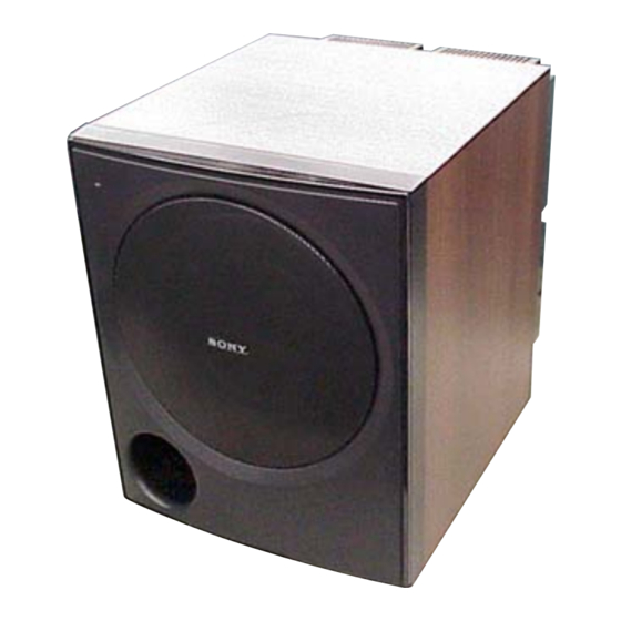
• Wood color type is the subwoofer in HT-DDW890/
DDWG800.
• Black color type is the subwoofer in HT-7200DH.
Sony Corporation
9-887-518-02
Audio Business Group
2008B05-1
Published by Sony Techno Create Corporation
© 2008.02
SPECIFICATIONS
AUDIO POWER SPECIFICATIONS (US model)
POWER OUTPUT AND TOTAL HARMONIC DISTORTION:
With 6 ohm loads, from 28 – 200 Hz; rated 120 watts, minimum RMS
power, with no more than 1% total harmonic distortion from 250
milliwatts to rated output.
Speaker system
Active subwoofer, Bass reflex, Magnetically
shielded
Speaker unit
8 inches (200 mm), cone type
RMS output
200 W (US model)
190 W (AEP and UK models)
Input
LINE IN (input pin jacks)
Power requirements
120 V AC, 60 Hz (US model)
230 V AC, 50/60 Hz (AEP and UK models)
Power consumption
80 W
Dimensions (w/h/d) (Approx.)
10 3/4 × 13 1/4 × 15 inches (270 × 335 × 380
mm) with foot
Mass (Approx.)
18 lb 5 oz (8.3 kg)
Design and specifications are subject to change without notice.
SA-WP890
ACTIVE SUBWOOFER
US Model
AEP Model
UK Model
Advertisement
Table of Contents

Related Manuals for Sony SA-WP890


Summary of Contents for Sony SA-WP890
- Page 1 10 3/4 × 13 1/4 × 15 inches (270 × 335 × 380 mm) with foot Mass (Approx.) 18 lb 5 oz (8.3 kg) Design and specifications are subject to change without notice. ACTIVE SUBWOOFER Sony Corporation 9-887-518-02 Audio Business Group 2008B05-1 Published by Sony Techno Create Corporation © 2008.02...
-
Page 2: Table Of Contents
COMPONENTS IDENTIFIED BY MARK 0 OR DOTTED LINE WITH MARK 0 ON THE SCHEMATIC DIAGRAMS AND IN THE PARTS LIST ARE CRITICAL TO SAFE OPERATION. REPLACE THESE COMPONENTS WITH SONY PARTS WHOSE PART NUMBERS APPEAR AS SHOWN IN THIS MANUAL OR IN SUPPLEMENTS PUBLISHED BY SONY. -
Page 3: Diagrams
SA-WP890 SECTION 1 DIAGRAMS THIS NOTE IS COMMON FOR PRINTED WIRING BOARDS AND SCHEMATIC DIAGRAMS. (In addition to this, the necessary note is printed in each block.) Note on Printed Wiring Boards: Note on Schematic Diagrams: • All capacitors are in µF unless otherwise noted. (p: pF) 50 •... -
Page 4: Main Board
SA-WP890 • IC Block Diagrams – MAIN Board – IC202, IC203 NJM4565D 8 V+ A OUTPUT 7 B OUTPUT A -INPUT 6 B -INPUT A +INPUT 5 B +INPUT IC500 uPC1237C-A SWITCH FOR OVERLOAD LATCH/AUTOMATIC DETECTOR RESET OUTPUT AC-OFF OFFSET... -
Page 5: Block Diagram
SA-WP890 1-1. BLOCK DIAGRAM J101 IC202 (1/2) IC202 (2/2) (AUDIO IN) BUFFER RV801 (VOL) Q301, Q311 IC203 (1/2) CURRENT REGULATOR RY301 RELAY IC203 (2/2) Q302, Q304 Q307 - Q310 PRE DRIVE (SPEAKER) Q303, Q305 Q731 CURRENT MIRROR SWITCH Q102 +V REG... -
Page 6: Printed Wiring Boards - Main Section
SA-WP890 • See page 3 for Circuit Boards Location. 1-2. PRINTED WIRING BOARDS — MAIN SECTION — • :Uses unleaded solder. MAIN BOARD • Semiconductor R309 R306 R326 Location Q310 Q307 R305 Q306 Q303 Q308 Ref. No. Location JW102 R316... -
Page 7: Schematic Diagram - Main Section
SA-WP890 1-3. SCHEMATIC DIAGRAM — MAIN SECTION — • See page 4 for IC Block Diagrams. R209 8.2k R208 5.6k IC202(1/2) NJM4565D Q102 R202 C201 2SC2785TP-E C203 C204 0.22 0.22 IC202(2/2) R207 NJM4565D R123 C120 C127 D101 MTZJ-T-72-15A J101 (AUDIO IN) -
Page 8: Printed Wiring Boards - Power Section
SA-WP890 Ver. 1.1 1-4. PRINTED WIRING BOARDS — POWER SECTION — • :Uses unleaded solder. 1-5. SCHEMATIC DIAGRAM — POWER SECTION — • See page 3 for Circuit Boards Location. POWER TRANS BOARD CNP401 MAIN BOARD CN402 POWER (Page 6) -
Page 9: Exploded Views
SA-WP890 SECTION 2 Ver. 1.1 EXPLODED VIEWS NOTE: • -XX and -X mean standardized parts, so they • The mechanical parts with no reference The components identified by mark 0 or may have some difference from the original number in the exploded views are not supplied. -
Page 10: Electrical Parts List
SA-WP890 Ver. 1.1 SECTION 3 INPUT CONTROL ELECTRICAL PARTS LIST MAIN NOTE: • Due to standardization, replacements in the • COILS When indicating parts by reference number, uH: µH parts list may be different from the parts please include the board name. - Page 11 SA-WP890 MAIN POWER TRANS SWITCH Ref. No. Part No. Description Remark Ref. No. Part No. Description Remark D307 8-719-991-33 DIODE 1SS133T-77 R310 1-249-408-11 CARBON 1/4W D308 8-719-991-33 DIODE 1SS133T-77 R311 1-215-888-00 METAL OXIDE D309 8-719-991-33 DIODE 1SS133T-77 R314 1-247-871-91 CARBON...
- Page 12 SA-WP890 Ver. 1.1 SWITCH Ref. No. Part No. Description Remark < CONNECTOR > * CN3 1-695-044-11 PIN, CONNECTOR (3.96mm PITCH) 2P * CN20 1-695-044-11 PIN, CONNECTOR (3.96mm PITCH) 2P < SWITCH > 0 S901 1-572-267-51 SWITCH, PUSH (AC POWER) (1 KEY)
- Page 13 SA-WP890 MEMO...
- Page 14 SA-WP890 REVISION HISTORY Clicking the version allows you to jump to the revised page. Also, clicking the version at the top of the revised page allows you to jump to the next revised page. Ver. Date Description of Revision 2007.01 2008.02...